The main goal of this thesis is to integrate the expertise related to the IEC61850 standard with the laboratory exercises of a data transmission course. This is done through careful design of the experimental setup, selection of tools and devices, and description of laboratory tasks and objectives. The experimental setup provides step-by-step configuration of the devices to be used in different tasks.
Tool selection depends on the configuration required for a specific lab session, but details of tools and devices are described in this document. The description of laboratory tasks concerns the work that the students must perform during laboratory hours. In addition to the written instructions of the telecommunication laboratory exercise for students and supervisor, the project provides detailed decoding information of GOOSE messages and a specific reading instruction prior to the laboratory exercises.
This thesis mainly describes the design, structure and implementation of the laboratory exercises using the VAMP Feeder Manager 257. Laboratory exercise documentation is not included in this document, but is provided separately to the respective instructor for use in his laboratory course.
Introduction
Equipments
- Vamp Feeder Manager 257
- VAMPSET Setting and Configuration tool
- IEC Simple Tester
- GOOSE Sender
- Wireshark
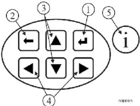
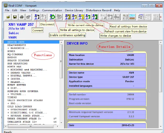
All functions and parameters of the relay can be found in the main menu on the left side of the software interface. For example, in VAMPSET there is a control panel with which you can operate the relay manager remotely, the push buttons on the panel are exactly the same as those on the machine. In addition, you can change the general configuration through the options in the main menu.
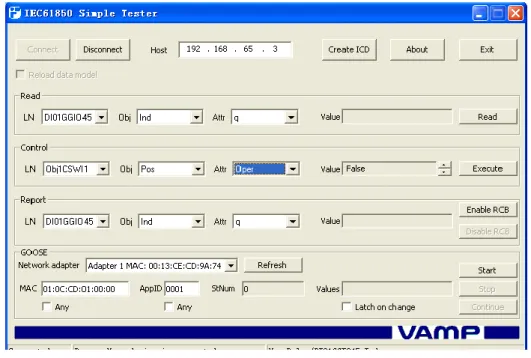
It contains some main functions such as reading values from the device and control switch inside the relay. In some cases the VAMP Feeder Manager will continuously send report to the control system to ensure that there is no problem, RCB is a model for monitoring this type of reports. Using this software, you can give a GOOSE command to the VAMP Feeder Manager and if there is related configuration in the relay, there will be some response from the relay according to the configurations made in the GCB.
It is easy for the user to see that all traffic is transmitted over the network.
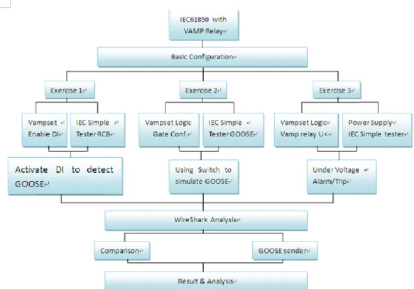
Laboratory Implementation
Configuration
Here you need to enter the password to configure the relay manager and the password is 0002.
Digital Input Implementation of VAMP Feeder Manager
- About this work
- Equipements
- Connections
- Configuration and Result
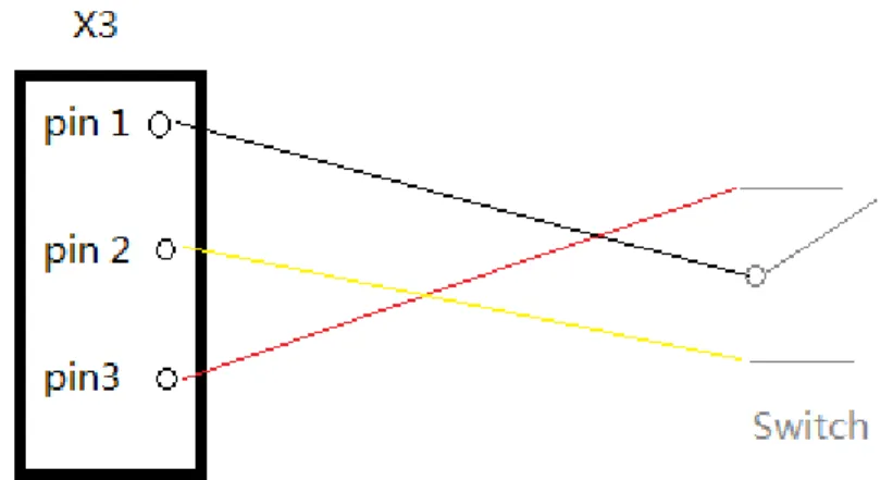
The PC and one of the Vamp relays are connected with the RJ45 cable using the Ethernet interface. An external 40 V DC power supply is connected to pin 17 and pin 18 (GND) of relay X3 terminal. After performing the previous configurations, continue to check the status of the enabled digital inputs.
Continue and repeat the same step to check the remaining digital inputs from pin 2 to pin 7 on the Vamp Relay. Once connected, boot up the device and software; choose the enabled digital input in the "Read" menu; i.e. after this configuration select Pin 1 from the rear selection slot and use a screwdriver to insert and secure the cable supplied with the equipment.
Do not fix the other end of the cable; just connect it to the corresponding pin and press. Now take out the non-screwed edge and click the "Read" button again and you found that the value is "False". The first pin on the digital input is 48V, the second pin is DI1 (digital input 1) once you connect these the 2 pin relay will send a message meaning when you connect DI1 to +48V you activate DI1.
In the control menu, you can only see the activated LN Obj1CSWI1, which refers to the circuit breaker. After the operation, you can clearly hear a sound from the VAMP Feeder Manager, which is that the switch turns off. When DI1 is active with, the cable value in RCB is "True", and when DI1 is not active, the value in RCB will immediately change to "False".
When there is an urgent situation in the line, RCB will report to the control system in real time, so that people can respond to those issues in time.
GOOSE message activated by an on/off event
- About this work
- Equipements
- Connections
- Configuration and Result
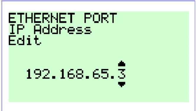
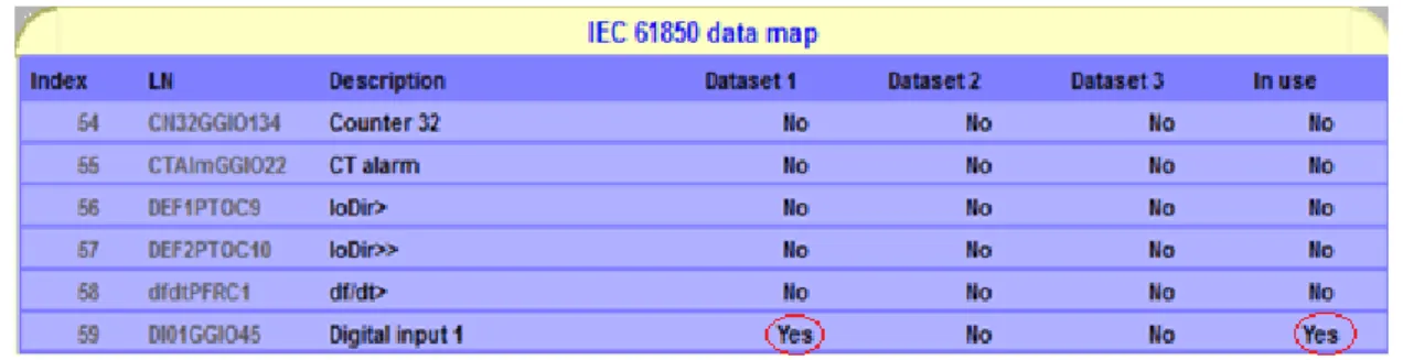
Do the same configurations in the Feeder Manager as exercise 1, for example the IP setting both in Vamp Relay and on the laptop. First, note whether DIs are related to GCB1 or 2 (GOOSE control block), so that when you activate DI1, you receive a GOOSE message. In this option, several LNs can be added to the GCB table so that the object of an LN is related to GOOSE messages.
When DI1 is added, its LN information is displayed as you can see in Figure 3.3.4.2. In "GOOSE configuration", GCB1 should be used and check the MAC address and application ID carefully. The application ID is for recognizing GOOSE messages, different models or IEDs have different application IDs for responding to those GOOSE messages.
In order to clearly see the changes after the GOOSE messages are sent on this map, the digital input must be connected to the LED that is on the Vamp relay in the logic. As soon as you complete this step, when you activate DI1, the "A" light on the VAMP relay will illuminate, indicating that a GOOSE message has been detected. You will use the GOOSE detector in the IEC Simple Tester to monitor the status of the GOOSE message at the end of this exercise.
There are many GOOSE messages in the transmission, so the IEC Simple Tester will select the one it needs. If you activate the "any" option, it will accept and monitor all GOOSE messages during data transfer. Each time it handles another GOOSE message, the number will automatically count to 1.
As can be seen now there are now 2 "F" in the block which means there are two LNs active in GCB1 and one is DI1 you. Each of these status changes will cause a GOOSE message to be sent and the value in the GOOSE message will be represented in this block in the form of "F" or "T". Whenever a GOOSE message is sent with a different Boolean value, the values in this block are updated in real time.
In this exercise, when you open/close the switch, DI1 will be rejected/enabled afterwards, a GOOSE message including False/True value will be sent to the operating system, which is the laptop you are using. At the same time, you will receive several frames with GOOSE messages in a short time via Wireshark.
GOOSE message activated by threshold event
- About this work
- Equipements
- Connections
- Configuration and Result
In this exercise, you will test the undervoltage function to get a GOOSE message. One of the most important functions of the VAMP Feeder Manager is to send an alarm signal to the control system when the mains voltage is too high or too low. In this type of emergency relay, the VAMP will send GOOSE messages with continuous multicasting for a short time interval until the control center resolves the problem.
Undervoltage is represented as U< in VAMPSET and you should enable this feature first. The reason for changing Un here is that this value has some kind of relationship to other values you will use later, such as Line Voltage. Note the "LVBlk" (Low Voltage Block) option, which means that if the line voltage is lower than the trigger value, the relay will block the line to avoid failure.
On the other hand, if you adjust the line voltage to 24V, the status changes to "Trip". The input signal must be an AC voltage (alternating current), otherwise no line voltage will be detected on the relay. Photo above shows the highest line voltage is 20V and is less than the trigger value.
The line voltage is now 27V which is more than 24V and clearly shows that the Alarm and Trip light is on. The final step is to make the VAMP relay perform the function of sending the GOOSE message so that you can capture the GOOSE message to study. To connect the function U< to GOOSE, the same step as in exercise 2 must be done, which is the activation of the LN of U< in GCB1.
After this setting, go to "GOOSE GCB1" label in VAMPSET, set another signal option as "VO6". As with exercise 2, at the end of this exercise the IEC Simple Tester is required to detect GOOSE messages. Before adjusting the mains voltage above 24V, which means that the mains voltage is blocked, you can find that the value in the GOOSE detector is “F”.
Now increase the amplitude of the function generator until the alarm message is sent by the relay and the status of the mains voltage is triggered. At the same time, the GOOSE alarm message is sent, the GOOSE monitor changes value from "F" to "T".

Conclusion