JONI SAIKANMÄKI: Inband Full-Duplex Technology for Multimode Multimode Radios: Applications and System Experiments. Because of this, the multifunctional radio with inband full-duplex capability can be successfully used in the military environment.
INTRODUCTION
- Background
- Scope and Objectives
- Contributions
- Outline
This means that MFR is able to simultaneously jam and intercept the opponent's receiver. Finally, MFR can be successfully used for defensive purposes by generating a so-called radio shield.
ELECTROMAGNETIC SPECTRUM OPERATIONS
Tactical Communications
- Requirements for Tactical Radios
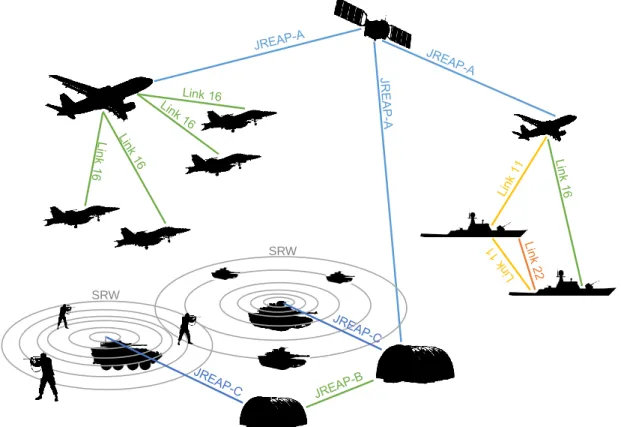
- Tactical Information Links
- Future of Tactical Data Links
Due to the mobility, the tactical radios can be deployed to armored vehicles, tanks or even jet fighters moving at high speeds [22]. By the late 1990s, NATO forces had over 25 families of radio systems offered by various vendors, which was the reason the US government became interested in the SDR technology.

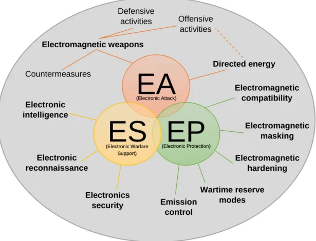
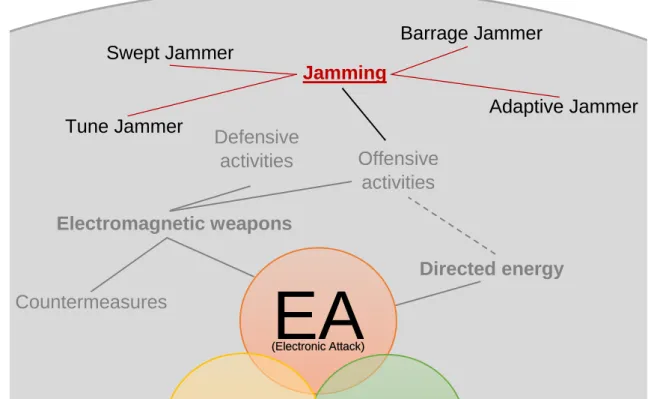
Electronic Warfare
- Electronic Attack
- Electronic Protection
- Electronic Warfare Support
- Operations and Electronic Warfare Tasks
If the adversary's bandwidth is known, it is not necessary to completely block the bandwidth with this type of blocker. One way is to provide training in both the conditions of adversary offensive electronic attack operations as well as the standard conditions during home station training activities. Minimizing the electromagnetic radiation of mobile phones can be understood as the emission control operation.
The electronic warfare support and SIGINT missions may use the same resources; however, these two differ in intent [18, 23]: What is the purpose of the task. As in the case of the electronic attack and electronic protection, there are several major actions related to the electronic warfare support and these are presented in fig. The same electromagnetic spectrum operations include the electronic warfare and its three elements of the electronic attack, electronic protection, and electronic warfare support, which have been told earlier.
The analyzes showed that electronic defense, electronic warfare support, and electronic warfare integration tasks are essential enablers and supporters of electronic attack tasks.
Multi-Functional Radios
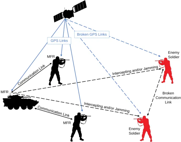
As mentioned earlier, the MFR radios are intended to operate in both civilian and military environments. The very investigation also defines the existence of the EA and the EP functionalities in the tactical environment. Here the MFR is able to tune itself to the EA functionality where it can sense frequency bands owned by the adversary and tune itself to an appropriate center frequency.
It is effective to set the center frequency of the MFR the same as opponents, which allows a particularly useful way to intercept and block the opponent. It should be noted that MFRs can also be used to jam the opponent's Global Positioning System (GPS) signal causing the opponent to lose their location information within the area of their operation. The GPS signal utilization results in the communication between multiple drones being hindered because these GPS signals can be effectively captured using the EP functionality in the MFR.
In a tactical environment, it would be essential to be able to take advantage of different functionalities at the same time, such as disrupting and intercepting the opponent.
FULL-DUPLEX RADIO TECHNOLOGY
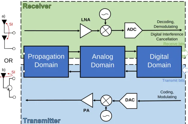
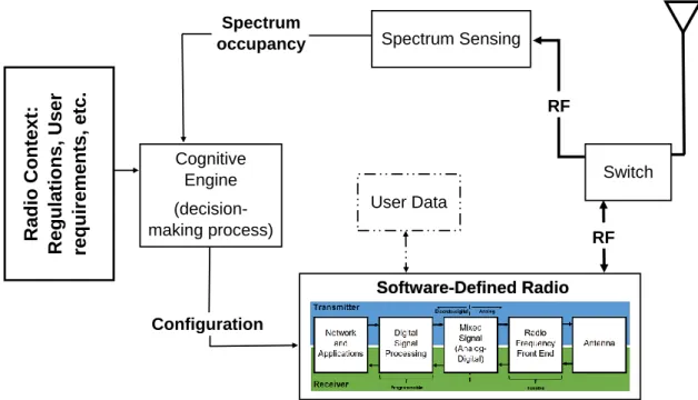
Inband Full-Duplex Transceiver Architecture
After this, the signal is processed in the digital domain which includes demodulation, bit decoding and interference cancellation to receive desired bit stream. In the propagation domain, the transmitter and the receiver block are separated or isolated using electromagnetic properties [48, 77]. The problem of the SI suppression in the propagation domain is that the desired signal is also often suppressed in the process [77].
The primary advantage of performing the SI suppression in the propagation domain stage is that the receiver's hardware later does not need to accurately process the received signal with an enormous dynamic range [65]. To work effectively, sufficient amount of SI suppression must be done in the propagation and the analog domain because ADC's dynamic range limits the amount of possible digital SI reduction. Then apply the necessary delay/gain/phase adjustments digitally and convert to the analog domain to use in the SI cancellation.
According to [39], 25 dB of SI attenuation can be achieved using nonlinear signal models in digital cancellation.
Applications in Multi-Mode Military Communications
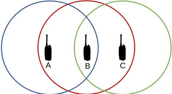
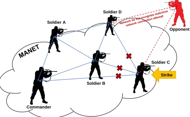
Another advantage that the IBFD mode has, not only in the military environment but also in civil applications, is the solution of the hidden terminal problem, which is illustrated in Fig. Other relevant benefits enabled by the use of the IBFD mode are collision avoidance/stacking, reduced feedback and an end-to-end delay when compared to the traditional HD mode. Next, we will move on to the disadvantages that the IBFD mode has when compared to the traditional HD mode.
The interference caused by the tactical radio transmit antenna on the receive antenna drowns out the weak input signal, reducing the gains of the IBFD mode. The SI greatly limits the benefits of using the IBFD transceivers and its cancellation is essential when developing MFRs in the military environment. Reliability and robustness are especially critical in military environments where IBFD technology is currently unable to respond compared to traditional HD technology.
However, the spectral efficiency brought by the ease of use of the IBFD mode would open up new opportunities for the military side.
Multi-Functional Applications in Electromagnetic Battles
- Defensive Applications
- Offensive Applications
Idea of the EP functionality can be easily linked to the previously mentioned EW tasks in Table 2.3. These can be combined so that the EA functions can be used in the MFR. This means that the IBFD mode can be used for the transmission of the storage signal to cause additional interference to the receivers of both red teams.
For example, using the EA functions in the MFR, it is possible to gain connection to defensive explosive devices and other self-defense systems of the allied team. In addition, the EA 5 task is related to jamming at the physical level, where the same jamming strategies can be used. Here, it is possible to jam the enemy's GPS signal while receiving tactical information from allied radios.
As a conclusion here, by utilizing the EA functionalities in MFR, a significant tactical advantage can be gained over the opponent.

PRACTICAL EXPERIMENTS
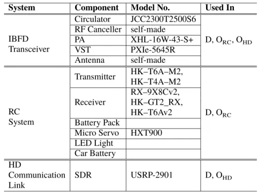
Experimental Equipment
- Prototype Multi-Functional Full-Duplex Radio
- Improvised Radio Control System
- Half-Duplex Tactical Communication Link
Using the IBFD transceiver [74] including circulator use, RF cancellation and digital cancellation, the SI can be suppressed by about 90–100 dB. The 𝜎 is variance, and the 𝐵𝑇 is bandwidth-time product which determines the width of the Gaussian filter. For practical implementation, the range of the𝑔(𝑡) must be limited, which can be seen in (4.2).
In this case, the signal sent through the Gaussian filter affects four of the previous and four of the following symbols. The transmitter's circuitry calculates the CRC of the payload by calculating checksum of polynomial and the payload. Width of the Gaussian filter is determined by the 𝐵𝑇 value already discussed earlier.
After that, a suitable sequence length is selected at the center of this vector.
Laboratory Experiments
- Scenarios
- Implementation
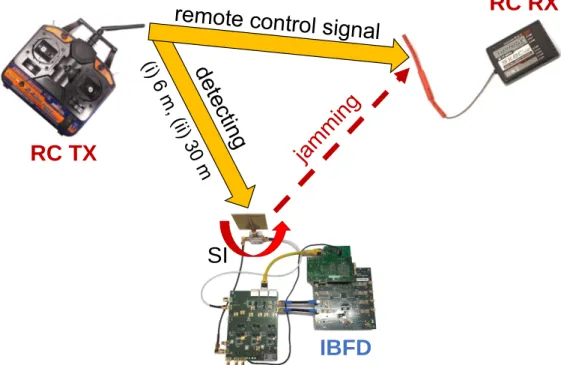
Also, research has been done on how these blocking strategies affect both receivers on the red team. In CaseORC, the blue team IBFD receiver is used for spectrum monitoring and signal surveillance purposes as Fig. Lab experiment case𝑂𝑅𝐶where blue team's IBFD transmitter detects and prevents activation of red team's improvised device (improvised TRCXX - RXlo. link).
Using the IBFD transceiver in the second offensive CaseOHD, the blue team is able to intercept the red team's tactical communication link as Fig 4.10 illustrates. The blue team is also able to jam the red team's receiver while listening to enemy transmission. The lab experiment case𝑂𝐻𝐷 where the blue team's IBFD transceiver intercepts and jams the red team's HD link.
Also, the effectiveness of the tactical blue team communication link is performed in the same way by recording the signal on the IBFD transmitter and thereby calculating the SINR.
Data Processing
Also in this case, the several received signal vectors from the red receiver and the blue IBFD transceiver are collected, which are later used for SINR calculation. After the digital cancellation, for channel estimation and thus the SINR calculations, the received vectors are equalized, which includes time and frequency synchronization. The received and transmitted vector must be aligned in time domain, which means time synchronization.
Also, the received and transmitted signal's carrier frequencies differ after a frequency down-conversion in a reception causing a frequency error 𝑧[𝑛]𝑒−𝑗2𝜋𝛥𝐶𝐹𝑂𝐹𝑠𝑛𝑠𝑛 , where 𝑋− 𝑓𝑅𝑋) is referred to as a carrier frequency offset (CFO) [ 70], 𝐹𝑠 is a sampling frequency, and 𝑧[𝑛] is a known transmission vector. So different𝜏en𝛥𝐶𝐹𝑂values are tried and consequently values that maximize the SINR are noted. After the time and the frequency synchronization, the training sequence ̂𝑧[𝑛] is used for a channel estimation.
Therefore, both sides of (4.11) can be multiplied from the left by a pseudo-inverse 𝒁̂+ = ( ̂𝒁𝐻𝒁)̂ −1𝒁̂where
RESULTS AND ANALYSIS
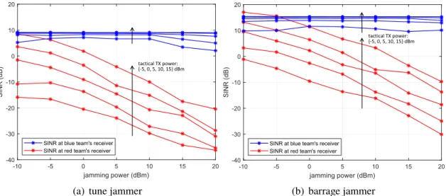
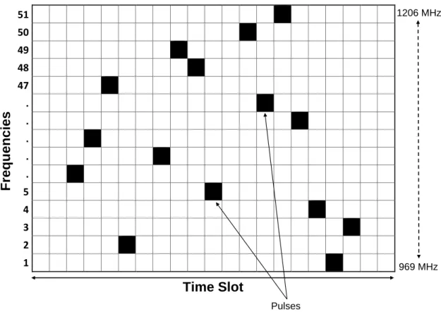
The high power consumption of jamming means that the tactical communication signal of one's own team can be completely covered. As seen in this later scenario, the FH pattern can still be effectively detected using cancellation techniques at MFR. Using the measured signal vectors at the red team receiver and the IBFD intercept receiver, the average SINRs can be plotted as Fig.
However, the quality of the intercepting IBFD transceiver can be maintained unchanged regardless of the jamming power. When we increase the storage power, the opponent receiver's SINR can be significantly reduced, while the IBFD transceiver's SINR remains at the same level regardless of the disturbance. For example, by using directional antennas in the direction of the opponent receiver, the jamming efficiency can be increased.
Using the barrage jammer increases the chances of successfully decoding the blue team's tactical information.
CONCLUSION
Future Work
Bailey, Practical Radio Engineering and Telemetry for Industry, 1st Edition, Newnes, Elsevier, Linacre House, Jordan Hill, Oxford p. Bullock, Transceiver and System Design for Digital Communications, 5th Edition, The Institution of Engineering and Technology p. Elmasry, Tactical Wireless Communications and Networks: Design Concepts and Challenges, 1st Edition, John Wiley & Sons Ltd, New Jersey, USA, September, p.
Elsworth, Elektronische oorlogsvoering, 1st ed., Nova Science Publishers, Incorporated, Defense, Security and Strategies, New York, VS, augustus p. Poisel, Modern Communications Jamming Principles and Techniques, 2e ed., Artech House, Norwood, MA, VS, maart p. Shankar, Fading and Shadowing in Wireless Systems, 2e ed., Springer International Publishing AG, Cham, Zwitserland, 2017.
Stanley, Understanding Voice and Data Link Networking, 1st ed., Northrop Grumman Corporation, 9326 Spectrum Center Boulevard, San Diego, USA, Dhjetor f.

![Figure 2.4 shows the slot structure of Link 16. It can have 127 different nets (0 – 126 numbered horizontal rings) with the vertical axis showing FDMA dimension of the trans-mitted waveform [22]](https://thumb-eu.123doks.com/thumbv2/9pdfco/1890081.266247/23.892.242.742.278.816/figure-structure-different-numbered-horizontal-vertical-dimension-waveform.webp)
![Table 2.3. The electromagnetic warfare tasks [54].](https://thumb-eu.123doks.com/thumbv2/9pdfco/1890081.266247/40.892.121.686.140.1159/table-the-electromagnetic-warfare-tasks.webp)
