The basic unit in a cellular radio network is the cell, where a base station provides the service for the mobile stations located in the cell area. The same frequency resource can be used again in the next cell or after some distance.

Overview of Radio Network Evolution
The important parameters that affect coverage and capacity are the transmission of the signal, the propagation environment and the quality of the received signal. The transmission of the signal is affected by the radiation power and the direction of the signal from the antenna, the transmitting antenna line and the transmitter.
Objectives
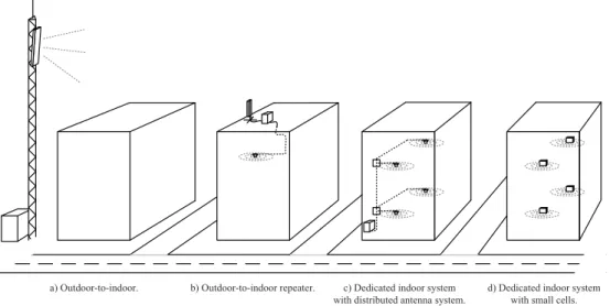
With the exception of the propagation environment and the receiving side of the mobile station, the parameters are selected when the radio network is planned. Therefore, the coverage and capacity of a mobile system can be greatly influenced in the planning phase of the system. a) From outside to inside.
Main Results
High gain improves repeater service area performance, but also increases macrocell uplink (UL) interference levels [P2]. Co-channel macrocell measurements show that an inner system has a clear, but local, influence on macrocell downlink (DL) performance.
Author’s Contributions
The unpublished measurements for the dense indoor placement performance analysis in Sections 4.3.3 and 4.3.3 were planned by the author and performed by Beatriz Molero Ródenas, M.Sc., who also collaborated on the analysis. The unpublished measurements for the HSUPA diversity studies in Section 4.3.4 were planned by the author and performed by Janne Palttala and Jaakko Penttinen, both of whom collaborated on the analysis.
Organization of the Thesis
The total noise power N is the thermal noise NT added to the noise from active circuits in the system. Operators must therefore use the same frequency band on multiple nearby transmitters in the system.
Radio Network Planning Process for
Dimensioning
In the dimensioning phase, rough estimates are made of the required coverage and capacity in the desired area. Based on these estimates, the network layout is prepared and an evaluation is made of the network elements involved, such as the amount of hardware required, the base station location and antenna height.
Detailed Planning
In the link budget, path losses between sender and receiver in uplink and downlink directions are calculated, taking into account the effect of all gains, losses and noise of the various network elements. As a result, the load on the network affects the maximum path loss and cell coverage range.
Post-planning and Optimization
1], fb is the share of active users among all users, and Ru [b/s] is the required average user data transfer rate. The topology planning process can be roughly divided into coverage predictions and system-level simulations for a large area with estimated traffic, followed by network performance analysis.
Indoor Planning
- Motivation for Dedicated Indoor Solutions
- Dimensioning
- Configuration Planning
- Topology Planning
In the dimensioning phase, information about the indoor propagation environment, such as the floor plan and construction materials of the building, should be collected. Next, potential antenna locations for coverage planning should be evaluated, followed by selection of antenna type, feeder line topology, and BTS or repeater location(s).
Solutions for Providing Indoor Coverage
- Single Cell Strategy
- Multi-cell Strategy
- Distributed Antenna System
- Outdoor-to-indoor Repeater
- Evolution of Indoor Configuration
Therefore, a multi-cell strategy (i.e. sector division) can be considered to expand both coverage and capacity in large buildings. For larger buildings with many users, a multi-cell strategy (Figure 2.3e) and e)) can be considered.

Indoor Propagation Environment
Outdoor-to-indoor Propagation
The total BPL value comprises penetration loss in the building, and path loss within the building [DT98]. The total indoor loss is calculated by adding BPL to the attenuation inside a building, as discussed in Section 2.5.3.
Repeater Donor Link Propagation Channel
Thus, the total internal loss can be much higher than the suggested 15 dB, but using higher values would result in a significant increase in the density of external base stations and the external coverage overlap. Whether or not a line-of-sight connection can be achieved depends solely on the parent outdoor cell and the location of the repeater donor antenna.
Indoor Environment and Propagation
Such models can be divided into empirical models derived from field measurements, physical models that analytically deal with different propagation mechanisms, such as diffraction and reflection, and deterministic models based on Maxwell's equations or beam-optical methods [Sau99]. Empirical models have many more limitations depending on how well the measurements can be generalized.
UMTS Release 99 Radio Access Network
WCDMA Radio Interface
Perhaps the most crucial physical channel is the reference signal, called a pilot channel and used for estimating radio channels. The term ij is the other-to-own cell interference, which in this case is different for each user due to different location.
WCDMA Access Technology in Indoor Environments
For a load higher than the set limit, radio resource management algorithms must limit the transmission power in the system by, for example, lowering data rates (quality requirements) of existing links and/or preventing the addition of additional links. The results indicate that dedicated indoor systems are able to provide better performance in terms of orthogonality compared to indoor coverage from outdoor cells.
High Speed Packet Access
Release 5 HSDPA
The procedure was sped up by bringing retransmissions from the RNC to Node B and down to the physical layer. In practice, with 30% channel coding, for example, the maximum bit rates are expected to remain around 10.8 Mbps at the physical layer.
Release 6 HSUPA
A single user can have all the available resources if needed, and multiple access principle is fulfilled by scheduling the resources sequentially for each user. Not all the UEs support full data rate as it depends on the HSDPA category of the UE. With 30% channel coding, for example, the maximum bit rates are actually expected to stay at around 4 Mbps on the physical layer.
Similar to HSDPA, the UE's data rate depends on the UE's category, where the number of codes, spreading factors, TTI, modulation, etc.
Release 7 HSPA+ and Beyond
UMTS Radio Interface Measurements
- UMTS Radio Interface Performance Indicators
- Practical UMTS/HSPA Indoor Radio Performance
- Coverage Planning
- Capacity Planning
- Impact of Mobility
The reception quality is estimated based on the amount of errors in the radio connection. The measuring devices in the thesis for downlink have been mobile stations (handheld, PCMCIA data card and/or USB dongle) or a scanner. The absolute errors in the measurements originate from the accuracy of the measuring UEs, where specifications set the extreme limits of the error.
In [P2, P3], the corresponding results are based on HSDPA indoor measurements with an outdoor-to-indoor repeater and dedicated indoor system. Functionality issues such as handoffs are not considered in the thesis, although some examples are given. For example, in [P2, P3] the delays cause degradation in the measured throughput in multi-cell configuration.

Implementation Aspects for Outdoor-to-indoor Repeater
The performance of a dedicated indoor system can be further improved by antenna selection, DAS hashing, cell hashing, and uplink diversity acceptance, as discussed in Section 4.3. An outdoor cell provides poor coverage inside a building, which is improved by an outdoor-to-indoor cell. In addition, although HSDPA always uses only one serving cell, poor dominance would cause all R99 and HSUPA links to have a soft handover, and uplink interference would occur in both participating cells.
If the performance of the repeater service area is preferred over the performance of the mother cell, the uplink gain of 1 dB may be acceptable and the gain may be set accordingly. However, if only minimal degradation is allowed in the stem cells, optimal placement occurs when increased uplink interference is not detected. This setting was also measured to provide a 13–87% improvement in HSDPA throughput in the repeater service area compared to the throughput provided by the external cell.

Performance Improvements by Antenna and Cell Configuration . 38
Densification of Distributed Antenna System
Densification of Indoor Cells
Diversity Reception
Diversity reception is a well-known and widely used technique to improve the quality of the received signal in wireless systems. Diversity reception in cellular systems is usually achieved by using two to four antennas, with spatial difference and/or different polarization. In [Tod92], indoor space diversity reception was studied with antenna separation below one wavelength, and a diversity gain of about 5 dB was measured in 1.7 GHz.
Measurement results for R99 downlink diversity reception indicate gains of 4-5.5 dB, although there is no mention of the antenna configuration used [Hep05]. Impact of diversity reception on single-user HSUPA performance In [P4], uplink diversity reception with HSUPA is measured. In the following section, the available capacity gain from diversity reception is illustrated by multi-user HSUPA measurements.

Coexistence of Indoor System with Macrocellular Networks
In [P5], the impact of an indoor network with different configurations on outdoor cell uplink and downlink performance was measured. For switching off, the impact of the indoor network on the quality of outdoor signals was first measured as idle mobile phones. In the thesis, the special characteristics of the indoor environment related to radio propagation and radio network planning were presented.
Aspects of radio network planning were discussed, with particular emphasis on WCDMA radio access technology. Studies have shown that the internal performance of UMTS and HSPA can be improved by several techniques related to radio network configuration. Measurements show that the internal system affected both the uplink and downlink performance of the external cell.
Future Development
Lee, "Antenne-afstandsvereiste voor een mobiele radiobasisstationdiversiteit", The Bell System Technical Journal, vol. MacDonald, "Advanced mobile phone service: The cellulaire concept", The Bell System Technical Journal, vol. Mogensen, "The downlink orthogonality factors influence on WCDMA system performance", inIEEE 56th Vehicular Technology Conference, 2002, pp.
Salbaum, "The Use of Microcells as a Means of Optimizing UMTS Networks," in Wave Propagation in Communication, Microwave Systems and Navigation, Jul 2007, pp. Abstract— The purpose of this paper is to show the special characteristics of the indoor environment to radio propagation and further to radio network planning. The signal strength received reflects the system characteristics and configurations – the denser the network in terms of base station density, the better the available network coverage.
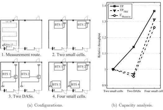
Abstract—The aim of the paper is to study the performance of HSDPA in indoor environment and to provide guidelines for HS-DPA coverage and capacity planning and selection of antenna configurations. For the antenna configurations (a)-(d) (Fig. 1), the cell scenario was isolated, i.e. the amount of inter-cell interference.


![Figure 4.2: Measured single user Release 5 HSDPA MAC throughput values (5 W HSDPA power) [P3].](https://thumb-eu.123doks.com/thumbv2/9pdfco/1890450.266616/45.918.272.597.445.700/figure-measured-single-release-hsdpa-throughput-values-hsdpa.webp)