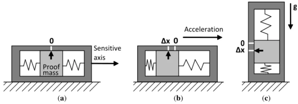
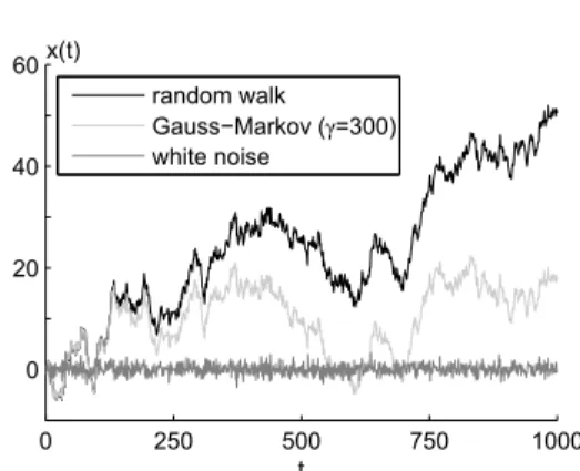
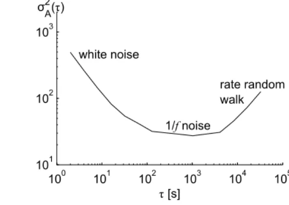
The expansion (or contraction) of a spring creates a force that is proportional to the displacement. In this way, the applied acceleration can be measured by measuring the displacement of the proof mass. Based on the Allan variance diagram, some characteristics of the sensor noise can be quantified.
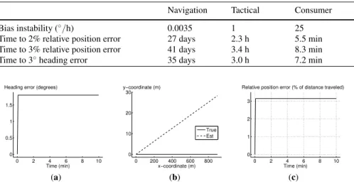
Sensor Quality Grade
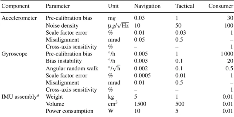
However, it is clear that the gap between consumer ratings and navigation is large – the differences are on the order of many decades. Distortion errors are not specified for consumer grade units because it is difficult, if not impossible, to separate their distortion errors from other crosstalk effects, such as interchannel electromagnetic interference; therefore, the total transverse on-axis sensitivity is given for these IMUs. Consumer performance figures represent low-cost, mass-produced MEMS sensors that have not been individually calibrated by the manufacturer.
When considering the size and power consumption of such a MEMS IMU, one must account for other necessary components such as the circuit board and readout electronics in addition to the sensor chip itself; these are not included in the sample figures given for a consumer grade IMU in Table 1. Nevertheless, it is not a challenge to build a MEMS IMU in a package with a size on the order of a few cubic centimeters. When considering the performance parameters and requirements of sensors, it is important to distinguish between errors before calibration and residual errors [55].
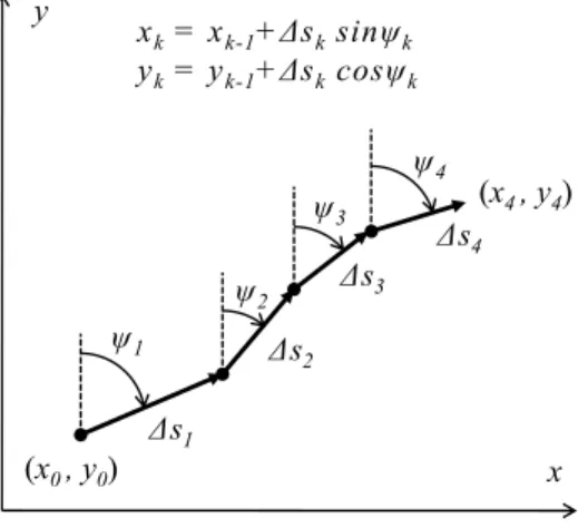
The term dead reckoning (DR) refers to the method where a new position estimate is calculated by adding measured or estimated displacements to the coordinates of a known starting point. As described in Section 1.3.1, position estimation with INS involves integration of gyroscope measurements to keep track of the sensor unit's attitude, followed by double integration of acceleration measurements to obtain velocity and position.
INS Mechanization
Because accelerometers measure the specific force rather than the true acceleration of the sensor unit, as explained in Section 1.1, the gravitational acceleration is added to the vertical acceleration component; this is straightforward when the accelerations are first transformed into a local-level frame (Eq. 11). In pedestrian applications, the cyclical nature of human walking can be used to enable low-cost inertial sensor navigation. The concept of foot-mounted inertial navigation depends on the idea that when the sensor unit is known to be stationary, velocity errors can be observed [19];.
The most important advantage of foot-based inertial navigation is the fact that it is insensitive to step direction and gait characteristics as long as the foot stance periods can be correctly detected. In addition, the foot is subject to greater dynamics than other parts of the body; the sensors are subject to significant shock whenever the foot hits the ground, which can lead to temporary measurement errors. In PDR, instead of double integration of accelerations, the walking speed is estimated from the periodic acceleration waveform caused by pedestrian movements.
Velocity can be estimated either from the main frequency of the periodic signal or by detecting individual steps and estimating their length and duration from the acceleration waveform. It can be shown that the PDR mechanization is superior to the traditional INS mechanization for a standing person when the sensors are mounted on the user's torso [44].
Step Detection with Accelerometers
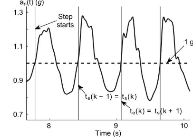
Since the sensor accuracy requirements are very strict for the INS mechanization requiring very high quality and expensive sensor units, the developers of mass market applications are looking for solutions where multiple integrations of sensor errors can be avoided. Most commonly, the step detection is based on accelerometers, but also gyroscopes can be used [14]. Instances of step onset ts(k) are detected by observing the g-crossings of the acceleration norm followed by a rate of rise and a peak height that exceeds the predefined limits, and requires that the time between the current and previous g-crossings is long enough.
The step end(k) is considered to be found when the next step starts or when a predetermined time, considered the maximum duration of one step, has elapsed after the start of the current step. The data for the figure was recorded using a sensor unit attached to the. Other methods that can be used to detect individual steps include the correlation of sensor signal with predefined step template [7].
The correlation method can be improved by using dynamic time warping (DTW), which allows a non-linear mapping between the template and the online signal [52]. There are applications and devices such as mobile phones where the orientation of the sensor unit cannot be assumed to be predetermined and constant.
Step Length Estimation
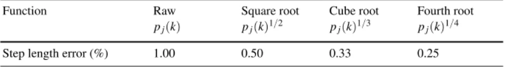
The use of combinations of these signal patterns has also been proposed [38, 32], as well as slightly different patterns than these [43]. In many cases, a nonlinear function, such as raising to a power or extracting from square root, must be applied to the signal pattern. The performance of stride length estimation with different functions applied to different signal patterns was demonstrated with real pedestrian data in [11].
A method based on the analysis of accelerometer and gyroscope patterns can be used to detect forward direction and climbing or descending stairs [36].
PDR Mechanization
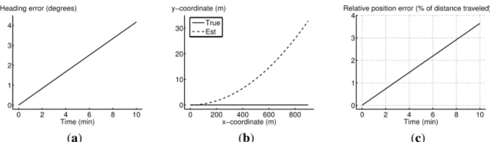
To determine the direction of the step, knowledge of the orientation of the device with respect to the environment is necessary, but not sufficient [36, 13]. Contrary to the bias error, the effect of the scale factor error on all other signal patterns except p1 is directly proportional to the sensor error. The development of the direction error, the error in the estimated position and the position error with respect to the distance traveled is shown in Fig.
The throughput scale factor error is assumed to be 1%, which corresponds to the scale factor uncertainty due to temperature sensitivity above 50 K in a consumer grade throughput [6]. The heading error, the estimated position error, and the position error with respect to the distance traveled are shown in Figs. Due to the constant direction error, the position error increases linearly with respect to time and x coordinates (Fig. 8b).
At the initial turn, the position error relative to the distance traveled jumps directly to more than 3% (Fig. 8c). That is, with the parameters used in this simulation and after a 180◦ turn, the error due to the gyro scale factor error is larger than the error presented by the best step length models in [11] .

Pattern Recognition
It should be emphasized that due to the limited size of the training dataset, the mean vector µj∈Rq and the covariance matrixΣj∈Rq×q are in fact estimates of the true model parameters. Further simplification is made by assuming that the prior probability P(C= j), where C= j indicates an event whose correct class is j, is known. For example, adding inferences for sequential data can be done using the Markov model for state transition probabilities P(Ct = h)|P(Ct−1=k) for all possible statessh,k=1,.
In practice, the assumption that the distributions and correlations between features are known is often invalid, as the feature set may include binary features, multimodally distributed features, and Wishart distributed features (due to sampling in the training phase). Thus, more generalizable and scalable methods such as gradient tree augmentation are popular in modern machine learning [10]. Although new machine learning methods require fewer input assumptions, there is still a need to understand what types of data and features need to be included.
When inertial sensors are used for classification, there are many opportunities for feature engineering if you have a good understanding of the basic principles of inertial sensors. Features can be extracted from raw data (angular degrees, specific force) or from integrated data (position, velocity, orientation).
Feature Extraction
To make the classification more efficient, there are efficient algorithms that can be used to reduce the dimensionality of the feature space by using the correlation between features [65]. The relationship between gyroscope measurements and device orientation with fast processing speed was shown in Eqs. The important feature in this equation is that the cross product terms remain zero if the gyro signal vector (ωAIAt . t) maintains its direction.
If the gyroscope signal is constant or the object can only rotate about one fixed axis, then there is no problem of non-commutativity. Typically, in inertial sensor processing, this is avoided by performing a fast speed update of the direction cosine relative to motion (or by using taper correction terms). To see why this is important in motion classification, consider the following scenarios for the time period n→m.
By combining the amount of taper error in each case we will see that the first example has a fairly large degree of non-commutativity, the movement of the vehicle is clearly smaller and in the static case the taper error is negligible. The quality of the sensors affects the input features, but on the other hand, the known motion mode can be used to detect, for example, gyroscope bias.
Classification Accuracy
In motion mode classification, the number of classes can vary greatly, affecting classification accuracy, but generally reported misclassification error rates are almost always below 10% [16].
Areas of Application
In: Proceedings of the 22nd ACM SIGKDD International Conference on Knowledge Discovery and Data Mining, KDD. Fairchild Semiconductor Corporation: FIS1100 6D Inertial Measurement Unit with Motion Coprocessor and Sensor Fusion Library (2016). Hanning, G., Forsl¨ow, N., Forss´en, P.E., Ringaby, E., T¨ornqvist, D., Callmer, J.: Mobile phone video stabilization using inertial measurement sensors.
Jahn, J., Batzer, U., Seitz, J., Patino-Studencka, L., Guti´errez Boronat, J.: Comparison and evaluation of acceleration-based step length estimators for handheld devices. Kourogi, M., Kurata, T.: Personal positioning based on walking motion analysis with independent sensors and a wearable camera. Ladetto, Q.: Walking navigation: continuous step calibration using both complementary recursive prediction and adaptive Kalman filtering.
Martin, H., Groves, P., Newman, M.: Runtime calibration limits of inertial mems sensors and sensor arrays. Mezentsev, O., Collin, J., Lachapelle, G.: Pedestrian dead reckoning – A solution for navigation in degraded GPS signal areas.