The main obstacle to the commercialization of the perovskite solar cells is their low stability. The performance of the fabricated cells was compared with the data available in the literature for the advanced solar cells and with those of the devices fabricated at the University of Cologne under inert conditions. I would also like to thank adjunct professor Hukka for introducing me to the field of solar cells and her precise examination of the writing of the thesis.
INTRODUCTION
These two compact layers and the two perovskite structures are applied to today's plate cells and thus show superior qualities in cell performance. Cell performance is evaluated by current-voltage (IV) measurement and scanning electron microscope (SEM) imaging. Furthermore, the main parameters for solar cell characterization and charge transport in the cell are discussed.
THEORETICAL BACKGROUND
- Fundamental Physics Behind the Solar Cells
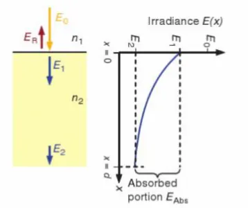
- Light Absorption
- Charge Transportation
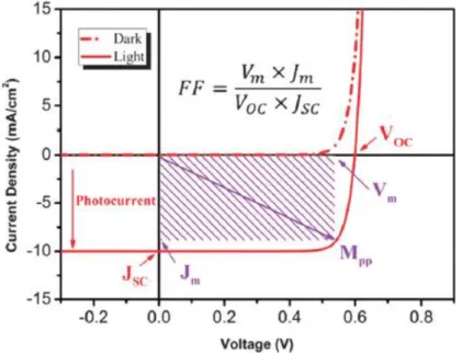
- Parameters for Solar Cell Characterization
Part of the incident radiation arriving at the surface of the cell (E0) is reflected (ER), part penetrates the cell (E1), and part of the penetrated radiation passes through the cell (E2). On the left is the absorption energy diagram, and on the right is a schematic representation of radiation absorption in a cell. Finally, the free charges recombine with holes or electrons in opposite regions of the cell.
PEROVSKITE SOLAR CELLS
- Perovskite Structure
- Single Cation Perovskites
- Mixed Cation Perovskites
- Triple Cation Perovskites
- Solar Cell Structure
- Electron Transport Layer
- Perovskite Layer
- Hole Transport Layer
- Solar Cell Architectures
- Mesoscopic Cells
- Planar Cells
- Stability Issues
- Device Stability
- Hysteresis Effect
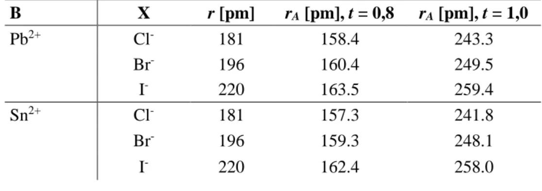
The thermal stability of CsPbX3 is excellent and the band gap strongly depends on the halide in the structure. The substitution of halides in the MAPbX3 perovskite structure has been extensively investigated, leading to notable differences in the electrical behavior of the perovskite. This results in a reduction of the effective cationic radius of Cs/MA/FA in the new perovskite material.
The absorption of light takes place in the perovskite layer that is located in the center of the solar cell. In addition to the electrical properties of the electron transport material (ETM), the contact between ETL and electrode and optimizing the interface between ETL and the perovskite layer play an important role in cell performance. The morphology of the ETL also influences the deposition of the perovskite layer.
It has been reported that the uniformity of the perovskite layer also depends on the thickness and homogeneity of the layer on which the perovskite is deposited (in this case ETL). Later PSSCs achieved 6.5% efficiency by optimizing the electrolyte structure and improving the fabrication of the perovskite layer [29]. In a mesoscopic PSC, a perovskite layer is deposited on top of a mesoporous framework layer (such as Al2O3 or TiO2).
This implies that the smaller thickness of the mesoporous layer is better when considering the cell performance. The metal oxide ETL material affects the stability of the perovskite solar cell and the manufacturing cost. Additionally, the scan history of the device and light exposure affect the hysteresis.
![Figure 3. Crystal structure of perovskite (adapted from Ref. [17] with permission of Elsevier, Copyright 2016)](https://thumb-eu.123doks.com/thumbv2/9pdfco/1890573.266739/17.892.277.697.110.434/figure-crystal-structure-perovskite-adapted-permission-elsevier-copyright.webp)
MATERIALS AND METHODS
Solar Cell Fabrication
- Compact and Mesoporous Layers
- Perovskite Layer
- Hole Transport Layer and Gold Evaporation
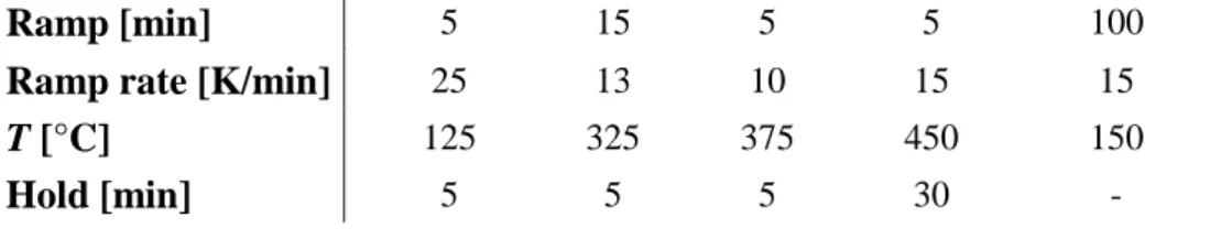
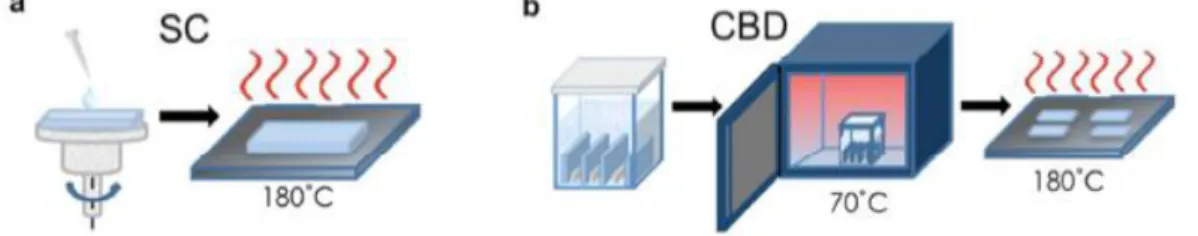
70 μl of Ti isopropoxide in absolute ethanol was deposited on the FTO plate and the spin program was started. 50 μl of the mesoporous solution was deposited on the sample and the spin program was started. Then the Kapton tapes were removed and sintering was started according to Table 3.
The solution was heated during the spin coating of all samples to avoid PbI2 crystallization in the solution. 60 μl of the PbI2 solution was deposited on the sample and the spin program was started. The samples were dried on a hot plate at 70 °C for 15 min after spin coating and the Kapton tapes were removed.
The solution was poured into an immersion vessel and the PbI2 film samples were vertically immersed in the solution for 20 seconds one by one. After spin coating, the Kapton strips are removed and the samples are placed on a hot plate at 100 °C for 30 min. The Kapton tapes were removed and the samples were baked at 100 °C in either vacuum or air for 1 h.
50 μl of spiro-OMeTAD solution was deposited in the sample and the centrifugation program was started with the following parameters: 4000 rpm, 2000 rpm/s and 20 seconds.
Solar Cell Characterization
- Current-Voltage Measurement
- Scanning Electron Microscopy
70 mM spiro-OMeTAD in anhydrous chlorobenzene was prepared by mixing the solution with TBP, 1.8 M LiTFSI in acetonitrile, and 0.25 M FK209 in acetonitrile stock solutions. The molar ratio of additives for spiro-OMeTAD was 3.3, 0.5, and 0.05 for TBP, Li-TFSI, and FK209, respectively, and the dopants were added to the spiro-OMeTAD solution in this order. Before the top contact was vaporized, the FTO contacts were cleaned with anhydrous chlorobenzene and the evaporative masks were obtained.
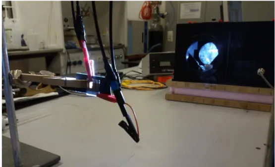
After evaporation, the contact areas were coated with silver paint to increase proper contact between the gold contacts and the alligator clips during IV measurements. In the figure, the solar cell is deposited in the position where the illuminance is determined to be 1000 W/m2 by the calibration of the reference cell. The cell is held in position with a wooden clamp and two alligator clips are attached to the contact areas of the cell to receive current data on the source meter.
The quality and thickness of the fabricated compact layers and the final device architectures were investigated by SEM imaging. With SEM, it is possible to obtain three-dimensional similar images of material surfaces. In SEM measurements, the investigated area of a specific material is irradiated with a finely focused electron beam.
The interaction between the electron beam and the analyzed surface produces different types of signals such as secondary electrons, backscattered electrons, characteristic X-rays in addition to other photons of different energies.
RESULTS AND DISCUSSION
Methyl Ammonium Lead Iodide Solar Cells
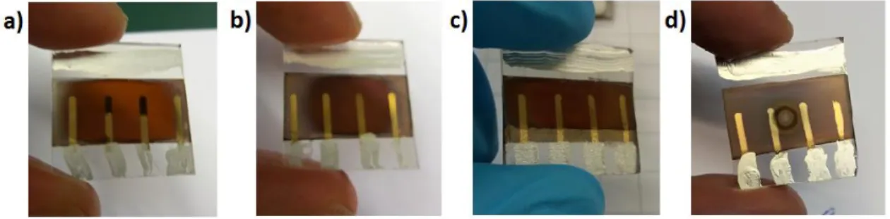
When annealed in air, the color of the perovskite appeared slightly brighter, and the surface of the film was not as shiny as last time. The best cell in the series achieved PCE of 1.67% and it also showed a clear decrease in FF, Jsc and Voc compared to the corresponding cells annealed in vacuum, as can be seen in Table 4. The perovskite crystallization approaches the yellow phase in the presence of oxygen and moisture, and this causes a decrease in cell performance.
The light color of the perovskite also indicates that the 1-step antisolvent method with MAPbI3 perovskite is an inappropriate preparation method under ambient conditions. The crack in the perovskite layer is the result of the uneven crystallization during the immersion in the MAI solution after PbI2 spin coating. The crack in the perovskite layer corresponds to a drop in cell performance due to limited charge transport in the crack region.
A slightly lighter color of the perovskite in Figure 11c compared to 11a is observed, indicating the influence of different underlying ETL to the perovskite morphology. The MAPbI3 perovskite layer starts to turn from brown to yellow in the presence of ambient air in minutes. The SEM images of the surfaces of SnO2 layers produced by both deposition methods are shown in Figure 13.
The pinholes in the SnO2 layer explain the poor charge transport and thus the poor cell performance of devices containing SnO2.

Triple Cation Solar Cells
- Influence of Electron Transport and Mesoporous Layers
The lack of the reports on this kind of behavior may be due to the lack of experiments on the fabrication of triple cation perovskite in the presence of ambient air and humidity. The formation of holes in the perovskite reduces cell performance in the same way as the cracks in the case of the 2-step sequential method. The reproducibility of the cells also improved when choosing the mesoscopic architecture and triple cation perovskite.
The cross-sectional SEM images of the mesoscopic and planar PSCs, with the triple cation perovskite and TiO2 ETL, are presented in Figure 17. Compared to the devices containing MAPbI3 perovskite, the cell performance of the triple cation-based perovskite composition is remarkably higher. The FF of the triple cation perovskite devices is on average higher and good for both device structures.
FF and Jsc for the devices with TiO2 are clearly higher, while the average Voc for the planar device with SnO2 is only slightly higher. The shape of the curves is relatively poor compared to the corresponding device with TiO2 produced by spin coating (Figure 16). In other words, triple cation perovskite, spiro-OMeTAD HTL and Au were deposited on top of the ETLs fabricated by TUT.
Finally, the stability of the best performing triple cation perovskite cell architectures was studied.
CONCLUSIONS
Wang, Recent Progress in Efficient Hybrid Lead Halide Perovskite Solar Cells, Science and Technology of Advanced Materials, Vol. Grätzel, Cesium-containing triple cation perovskite solar cells: Improved stability, reproducibility and high efficiency, Energy Environ. Correa-Baena, Highly efficient and stable planar perovskite solar cells from solution treated tin oxide, Energy Environ.Sci, Vol.
Il Seok, Solvent Engineering for højtydende uorganisk-organisk hybrid perovskit solceller, Nature Materials, Vol. Yang, Improved Air Stability of Perovskite Solar Cells Via Solution-Processed Metal Oxide Transport Layers, Nature Nanotechnology, Vol. Huang, Stability of Perovskite Solar Cells: A Prospective on the Substitution of the A Kation and X Anion, Angewandte Chemie International Edition, Vol.
Choi, Low Temperature Processed Perovskite Solar Cells Without Hysteresis with 19.1% Efficiency, Energy Environ. Qi, Post-Annealing MAPbI3 Perovskite Films with Methylamine for Efficient Perovskite Solar Cells, Materials Horizons, vol. Lin, Improved Stability of Perovskite Solar Cells in Ambient Air by Controlling the Mesoporous Layer, Journal of Materials Chemistry A, Vol.
Yan, Efficient and Stable Perovskite Solar Cells Prepared in Ambient Air Regardless of Humidity, Nature Communications, Vol.