The research is limited to examining the sheet metal process from design to production, focusing on the programming department. For the case study basis, process flow charts were developed based on the most important aspects of the company's sheet metal process.
INTRODUCTION
Background
Research problem, targets and limits
Thesis structure
LITERATURE REVIEW
Reserch methodology and materials
- Literature review
- Case studies
- Information analysis
Based on the theory and generated schematics, an overview of the entire sheet metal process can be formed. The current state of the process could be assessed on the basis of the previous process models and the associated theory.
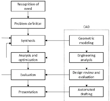
Design
The fifth phase, evaluation, measures how the new product meets the requirements set during the problem definition phase. In some cases, the evaluation can be done before manufacturing using design software, which e.g.
Programming
- Numerical control systems
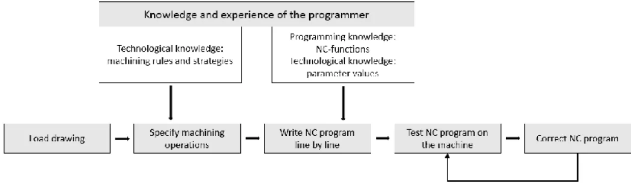
- Manual part programming
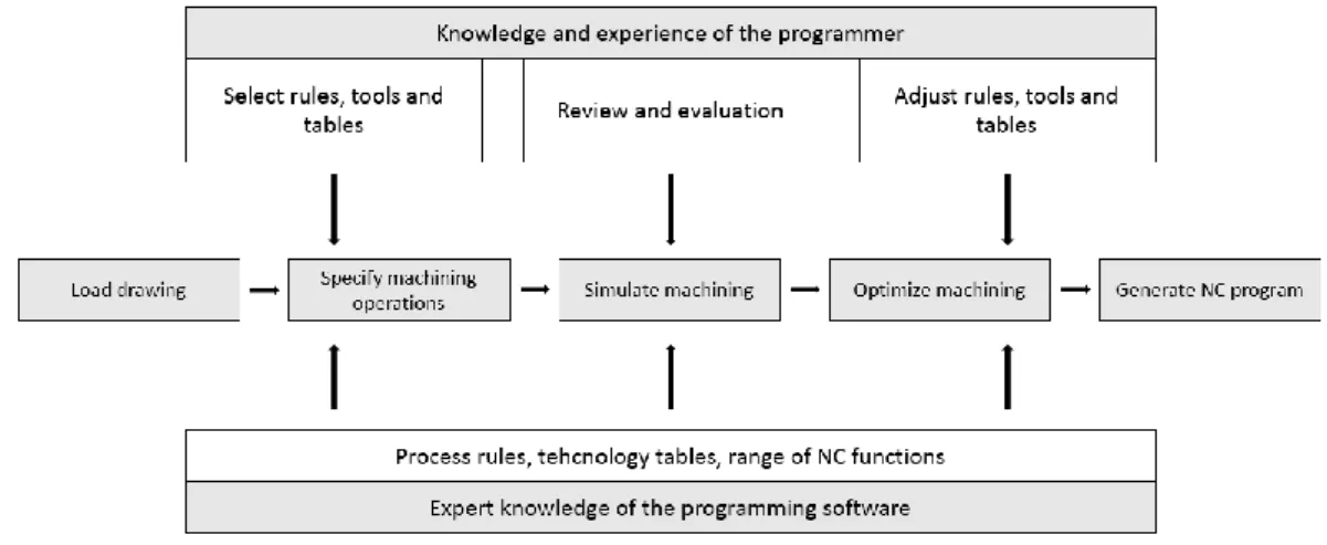
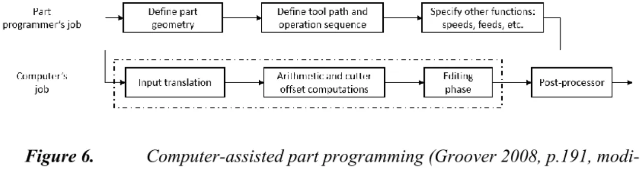
- Computer-assisted part programming
- Part programming using CAD/CAM
- Manual data input
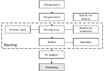
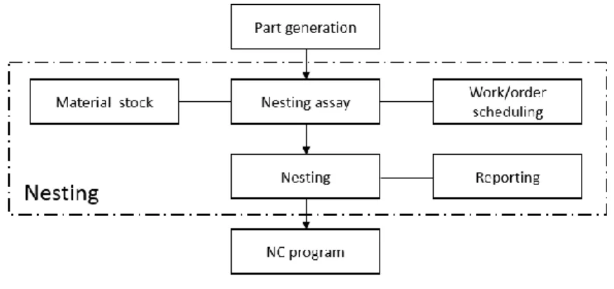
- Nesting
The process is carried out step by step and the program's instructions are carried out by the machine's control unit. How it can be managed from design to the embedding phase is the real challenge for the company.
Flat processing
- Laser cutting
- Punching and forming
- Shearing
In the workplace of moving material boxes, the workpiece moves relative to the stationary cutting head. From an operational point of view, sheet positioning plays an important role in the quality of the final product.
Bending
- Geometric tolerances
- Press brakes
- Springback
- Bend allowance
In manufacturing, these factors are backlash, material properties, tools, thickness and workpiece width. Due to the degreased setup time, the workpiece can be bent in one cycle, with the back gauge automatically repositioning for each step. Depending on the scope of the sheet metal processes, over 100 tables can easily be required based on each tool, material and thickness.
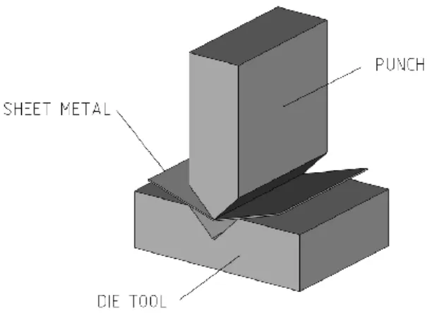
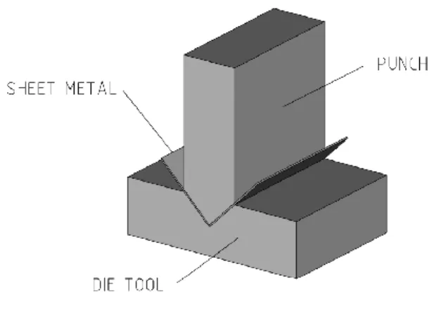
These points are both edges of the die cavity, also known as the v-tool or bottom tool, and the punch tool. In practice, the punch presses the workpiece into the lower die without collision between the workpiece and the bottom of the die. In other words, the workpiece is never pushed into the bottom of the die, as shown in Figure 10.
As a result, the corner of the part bends back slightly when the tension is released after bending. The sensors measure the springback angle and it is automatically compensated during the bending process. This overbending is a local operation, where the experience-based knowledge of the operator is important for the quality of the end product.
Assembly
- Joining processes
- Mechanical fastening
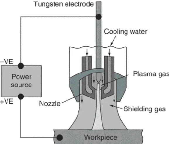
2011, p.252) explain that in these cases a standard table of the k-factor only gives a good approximation for these values. After the procedure, the experimental bending data can be incorporated into the CAD/CAM environment. The used plasma gas is formed into plasma by ionization in the inner nozzle.
TIG welding, shown in Figure 14, is one of the most important thermal plate joining methods. It is a gas arc welding method where an electric arc is generated between a tungsten electrode and the workpiece. It is then allowed to cool under pressure, thereby ensuring the piece's sufficient strength.
The use of threaded fasteners is one of the most popular joining methods that generates a strong and flexible joint between parts. In this method, a core hole is first cut and in the second operation, the tool forms the thread. At the target company, the use of mechanical joining methods closely follows the guidelines (USPHS 2011) of the U.S.
Cost structure of sheet metal parts
INFORMATION AND OPERATION MANAGEMENT TOOLS
- Basics of information and knowledge
- Product Data Management (PDM)
- Enterprise Resource Planning (ERP)
- Computer-Aided Design (CAD)
The core of the PDM is to create, store and store information related to the products of the company. The product data management also allows version and revision tracking of the product, which is a significant boost compared to the current one. This is a good example of using embedded data in the current production process.
In addition, in the case of the target company, sheet metal design is the most important part of the design process. The folded sheet metal part of the 3D world is bent open on a single sheet surface. In this case, the designer must manually calculate the changes in the length of the sheet in bending.
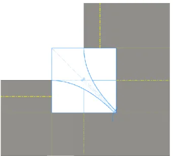
The bending of the sheet parts should be facilitated in the design phase by placing the corner relief in the intersection of the bending line. This is just one example of the shapes, but they all need to be manually added to the model. For the products that the company makes, it is important to know the grinding direction of the sheet metal part.
CURRENT SITUATION
Available systems
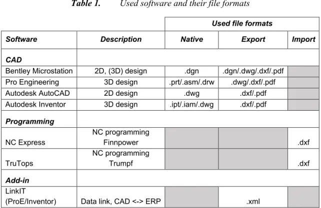
This section introduces the design software used by the company and the software services that support it. Data transferred between the software must be modified several times when transferring data from one program to another. At the moment there are three design software in use in the design department and two of them are intended to be replaced.
According to this design geometry, the design department in Poland will make a new design so that the product can be manufactured. The software is used for most mechanical constructions such as the construction of drawers, canopies, hoods and refrigerators. In addition, consideration of experiential forms on a library basis has increased design efficiency.
The implementation of this software is ongoing, and if the benefits of the software prove to be positive, the use of this software can be extended to the furniture design in Finland. The software is currently used in the programming department, where three programs produce the necessary software for the machines. This is done according to the design data shared by the design department in .dxf format.
Transition to the new system environment
The new system environment could provide a solution to include this data in the production systems, which would enable partial automation of the process. At a later stage, alternatives should be considered that integrate the CAM systems into the design work. Now the design department produces design documents for the product, from which programmers adapt the information according to the machine basis and the needs of the manufacturing methods.
Increasing the machine base
In that case, it will be examined whether it is cheaper to run machines in three shifts with less personnel than to run three machines in two shifts.
MAPPING THE SHEET METAL PROCESS
- Design process
- Re-manufactured products
- Publication of drawings
- Part programming and nesting process
- Laser cutting, punching, and shearing process
- Bending process
At the same time, the plate to be used determines the maximum dimensions of the plate blanks. Using the same add-on service, the BOM for the assembly can be transferred to the ERP. According to the list, the operator of the guillotine cutting machine has enough information to cut the parts for production.
When nesting, the grinding direction of the parts must be taken into account, which presents a challenge for the use of sheet metal. The programmer must consider the size and material of the nesting sheet. The material of the parts is represented in the CNC block supplied by the logistics department.
In addition, reports of the nests are generated and shared for the operators of the production. The cut list contains the dimensions, material and quantity of the parts to be cut with the guillotine. The operator of the laser machines receives information about the parts from the laser report, which of them should be cut.
CHALLENGES AND DEVELOPMENT
- Information flow errors
- Human based errors
- Revision management
- Avoiding manual work
- Other observations
The second case is related to the material list, a file that the programmers use to get information about the material available in the store. Based on the interviews, it became clear that material handling is a challenge if the material used in the product does not correspond to the information in the ERP. This would also require that the manufacturing method of the part could be decided during the design phase.
In the current model, the designer must travel from the office to the production facilities to obtain this information. The situation is the same the other way around, so there may be cases where the master document product is different from the produced product. Programmable parts of existing combined machines can be programmed with the same software due to the machine base.
With the new laser machine, consideration should be given to how the cutting of parts would be prioritized. The challenge in this situation is that the parts programmed in the old machines are not suitable for cutting with the new machine. In this case, the bent part would be released into production sooner compared to the current model.
CONCLUSION
What happens if you received an order from Finland and what are the main stages of work after that. Have you had a situation where the part was remade caused by a Finnish design flaw? Are these design tasks based on human knowledge or do you have a library for these special shapes.
What kind of drawing is shared by the software team and whether it is an expanded drawing or a scaled-down version. Do you have a database or library where you can get the necessary technical parameters like material thickness, standard shapes, etc. Is there some information available for these stages and do you have a guide/manual or design library where I could get this information.
Or is it determined by others and the deadline indicates when it should be ready. Is it that the production planning system indicates what to do and which plates are in stock? Are there other work stages that directly affect the sheet metal process, such as designing, cutting or bending.