Based on the aforementioned analysis, it is shown that the addition of the bidirectional DC-dc converter (double-stage inverter) is necessary if the battery terminal voltage is lower than that required for the direct (single-stage) inverter connection. Due to the cascaded control scheme of the inverter, faster regulation of the PV voltage can be implemented in the double-stage scheme.
INTRODUCTION
Both photovoltaic (PV) and EES systems require power electronic converters to be controlled and connected to the grid. The optimized solution is influenced by various requirements and constraints, such as the selected application, the system rating and the selected PV system.
GRID-CONNECTED PHOTOVOLTAIC
GENERATORS AND AN ENERGY STORAGES
Photovoltaic Generator
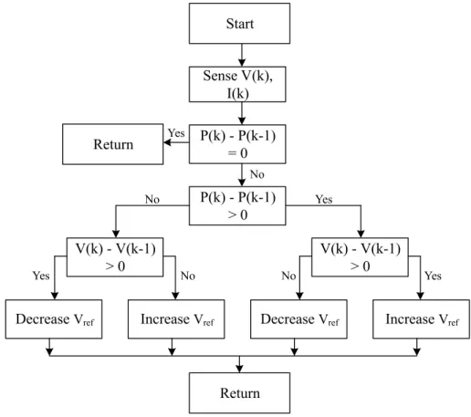
- Maximum Power Point Tracking
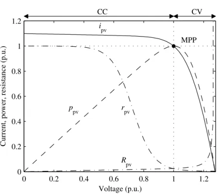
First, to control the terminal conditions of the PV module to maximize the energy produced. The goal of MPPT is to control the switching of the converter to adjust its input voltage to match the MPP voltage of the PV array.

Electrical Energy Storage
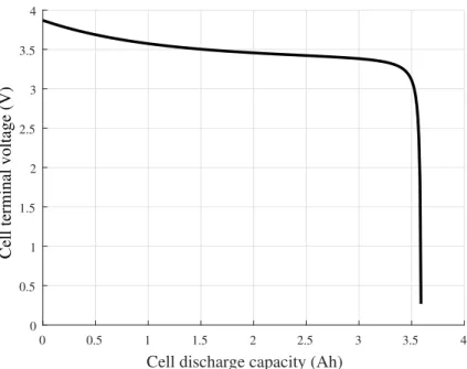
The relationship between the battery charge and the battery terminal voltage is demonstrated in Fig 2.6. To prevent the battery cells from discharging on their own, it is important that the voltages and charges of the cells are close to each other.
Small-Signal Modeling of a Photovoltaic Inverter
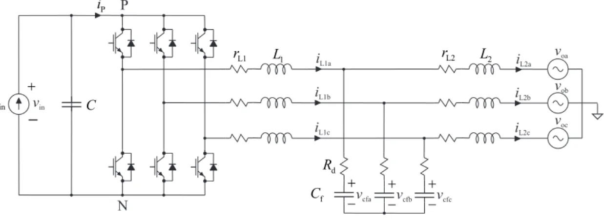
To model the inverter, the moving average in the state space model [10] is used. It consists in obtaining the weighted average state of the circuit with respect to the duty cycle of the operation during a switching period. To derive the average model of the system, Kircho's voltage and current laws are used to derive the differential equations that describe the dynamics of the system.
The steady-state operating point can then be determined by setting the derivatives to zero and replacing all variables with their respective steady-state values. Finally, according to [10], a linear model of the converter is derived to describe its behavior to small variations around the operating point. This is done by linearizing the mean model at the steady-state operating point using the first-order Taylor series expansion.
Thus, the small-signal dynamics is given in state-space form. where the matrices A, B, C and D are dened as. 2.8) The capital letters refer to the steady-state values and the dot above a variable refers to its time derivative. Using the Laplace transform, the open-loop transfer works from dˆd to ˆiL1d (GcLdd−o), dˆq to ˆiL1q (GcLqq−o), and dˆd to vˆin. a) Input voltage and output current d-component control (cascaded control scheme). The mains current and the voltage on the DC side must thus be controlled in a cascaded manner, whereby it is controlled in the outer loop and L1d in the inner loop.

ACPV
AC i o-abc
Small-Signal Modeling of a Photovoltaic Boost Converter
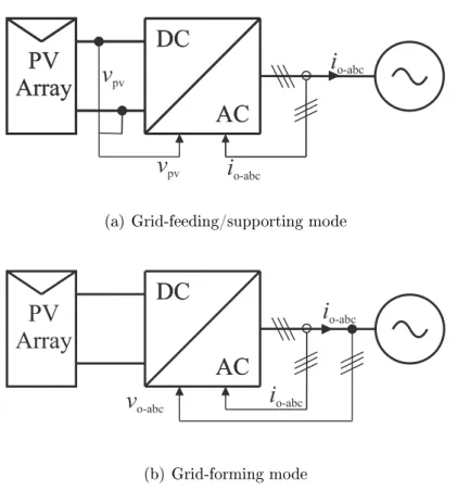
In two-phase PV systems, a dc-dc converter is inserted between the grid-tie inverter and the PV generator, as shown in Fig. This is achieved by controlling its input voltage, i.e., the voltage in the PV grid. However, its main function is to control the dc link voltage instead of performing MPPT.
Both DC-DC and DC-DC converters control their input voltages and should be analyzed as current-supplied current-output converters. By using Kircho's voltage and current laws to solve for the state derivatives and output variables, and averaging these equations over one switching cycle, the system is averaged. By setting the derivatives to zero and replacing all variables with their corresponding steady-state values (shown in capital letters), we obtain the equilibrium state.
Finally, the linear model of the boost converter describing its behavior for small variations around the operating point is obtained by linearizing (2.12) at the steady-state operating point using the first-order expansion of the Taylor series. The dynamics can be obtained by solving the transfer functions between the input and output variables in the frequency domain. By using Laplace transform, the open-loop dynamics of the converter can be presented with transfer functions as.

Small-Signal Modeling of a Bi-Directional DC-DC Con- verterverter
Therefore, only the small-signal model for the buck mode is derived here, and the model for the boost mode is obtained by reversing the low voltage (battery) and the higher voltage side parameters as well as the direction of the current. Furthermore, the duty ratio equal to d in the boost mode is replaced by its complementary, i.e. 1−d, which corresponds to the duty ratio in buck mode.

INTEGRATING AN ENERGY STORAGE TO A PHOTOVOLTAIC INVERTERA PHOTOVOLTAIC INVERTER
- Component Ratings
- Limits for the Photovoltaic Module
- Limits for the Battery Module
- Eciency and Losses
- Modularity
- Cost and Prot
- Converter Control
- PV Inverter Control
- Battery Control
Similar behavior does not occur when the dc-dc converter is used to control the voltage instead of the inverter. Thus, to achieve MPP voltages lower than this limit, the dc-dc converter is required to control the voltage across the PV modules instead of the inverter. According to [5, 16], to achieve a sufficiently high input voltage for a single-phase inverter in European systems (230 Vrms) to control the voltage across the PV modules with the inverter instead of additional dc. DC conversion stage, a minimum of 16 PV modules in series is required.
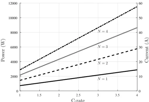
When the battery current is directly controlled by the inverter, the input voltage of the inverter is determined by the battery voltage. The voltage and power of the battery as a function of the number of cells connected in series are shown in the figure. Furthermore, in a single-stage EES connection, the input voltage of the converter is directly determined by the EES voltage.
However, since the dc-dc conversion losses do not occur in the single-stage topology, the overall efficiency of the system is higher. During the lifetime of the PV generator, the PV modules may need to be replaced due to a malfunction, etc. In the case of the grid-forming mode of the inverter, a bi-directional DC-DC converter is required to control the battery power, as the inverter cannot be used to perform that functionality as was possible with the power converter.

PERFORMANCE EVALUATION
- Parameters and Controller Tuning
- Experiments
A dividing frequency of two hundredths of the switching frequency (ie 400 Hz) is chosen and the following. The selected regulator parameters are given in Table 4.4 and the regulator loop gain is shown in Fig. The selected parameters are given in Table 4.4 and the regulator loop gain is shown in Fig.
The selected parameters are given in Table 4.4 for both single-stage and two-stage PV inverter and the controller loop gains are shown in Fig. 4.10(b) with the green line and the orange line dictates the sum of PV power and battery power. Problems occur, for example, when the PV modules produce too much power and the battery load is too high for the battery to charge.
Dual stage PV inverter topology is used and the grid reference is set to 500 W, shown in the figure with the orange line. The battery power is shown with the green line and the PV power with the blue line. The battery is set to discharge when its charge becomes higher than 90% and the PV modules are set to produce reduced power.
The power produced by 2 PV modules, the compensating battery power and the sum of these forces. The power produced by 8 PV modules, the compensating battery power and the sum of these forces.

CONCLUSIONS
The single-stage inverter is particularly advantageous if MPPT speed and mismatch losses are not a concern. This is the case, for example, if the irradiance remains at high levels even with uctuation, since the variation of the MPP voltage at high irradiance is relatively smaller than at lower irradiance levels, even when the irradiance varies (see Fig. 3.2 or Fig. 3.3) ) . Although, as mentioned, it is important that the minimum voltage across the PV modules must meet the requirements of (3.1) to avoid overmodulation.
Due to the cascaded control scheme of the inverter, where the DC side voltage is controlled in the outer loop and the AC side current d component in the inner loop, the regulator operates in a more eective manner if the input voltage does not experience high uctuation. This is not the case if the inverter is used to control the voltage across the PV modules instead of the DC link voltage. Finally, as demonstrated by performing real-time simulations with real irradiance data, the battery can be used for intermittency attenuation to compensate for the fluctuations in the PV power (power balance), thus providing constant power to the grid.
The transducers used in the simulations were tuned based on their small-signal models using a loop-shaping technique.
BIBLIOGRAPHY
Blaabjerg, An overview of single-phase grid-connected inverters for photovoltaic modules, IEEE Transactions on Industry Applications, vol. Lai, Battery energy storage station (BESS)-based mitigation control of photovoltaic (PV) and wind power generation orders, IEEE Transactions on Sustainable Energy, vol. Hansen, Design and control of an LCL - filter-based three-phase active rectifier, IEEE Transactions on Industrial Applications, Vol.
Suntio, Photovoltaic generator as an input source for power electronic converters, IEEE Transactions on Power Electronics, vol. Yu, A high-efficiency grid-connected battery energy storage system, IEEE Transactions on Power Electronics, vol. International Exhibition and Conference on Power Electronics, Intelligent Motion, Renewable Energy and Energy Management, May 2014, p. 2008).
Carrasco, Energy storage systems for transportation and grid applications, IEEE Transactions on Industrial Electronics, vol. Agelidis, A review of power electronics for grid connection of utility-scale battery energy storage systems, IEEE Transactions on Sustainable Energy, vol. Kuo, Comparison of energy losses of single-phase and two-phase grid-connected photovoltaic systems, IEEE Transactions on Energy Conversion, vol.
SET-UP


![Figure 2.5 Power and energy densities of dierent EESs [9]](https://thumb-eu.123doks.com/thumbv2/9pdfco/1890829.266995/20.892.258.678.114.419/figure-power-energy-densities-dierent-eess.webp)