In the introductory part, we discuss the set of problems, related to HetNets, and review the HetNet development process. At the end of the introductory part, a set of HetNet-related demo activities are demonstrated.
List of Publications
1 Introduction
- Research Motivation
- General Background on HetNets
- Main Contributions and Scope
- Structure of the Thesis
In the final chapter of the thesis, there is a discussion of the applicability of the proposed solutions. In addition to this, there is a separate analysis of the mmWave RAT, as the most likely.
2 HetNet Components and Architectural Options
HetNet RAT Candidates
- WMANs and WLANs Evolution
- MmWave RATs
The first step towards commercial use of higher frequencies was taken by the IEEE, which developed the 802.11 advertisement standard in 2009 [29]. In practical terms, this means that the power blocking, i.e. the placement of even a small object between transmitter and receiver can lead to discontinuities or a complete stop in transmission.

HetNet Architecture Design
- Network Entities and Their Roles
- Standardization Efforts
- Other Possible HetNet Enhancements
In addition, part of the EPC functionality is transferred to H-CRAN to accelerate latency sensitivity. To implement this functionality, some central management units are virtually created within H-CRAN.
![Figure 2.3: E-UTRAN-EPC functional split, [1]](https://thumb-eu.123doks.com/thumbv2/9pdfco/1890881.267047/21.748.124.588.290.584/figure-e-utran-epc-functional-split.webp)
HetNet Applications
- H2H Traffic Offloading
- MTC as Part of HetNets
- Drone Users and Mobile Drone Cells
MTC differs significantly from traditional H2H applications in terms of applications, equipment, and traffic mode [52]. In addition, there are several directions of development for MTC communication. For standalone solutions working in the unlicensed spectrum, there are many narrowband protocols such as LoRa [53, 54] and Sigfox. LTE-MTC (or LTE-M) solutions define a set of changes to the LTE standard that, when combined with new UE types (Cat 1, Cat 0, Cat M1), reduce the cost and power consumption of the end device.
While LPWA standards should theoretically cover all MTC applications [61], in practice there are still many open questions related to energy efficiency, coverage, price per unity and security. In this case, the potential communication range is tied to the coverage of the cellular network, which usually means much wider horizontal distances. This will require solutions to the problems related to drone positioning, energy efficiency and backhaul between UAV-based AP and core network [65].
![Figure 2.6: Options for HetNet architecture for an LTE-based network [P2]](https://thumb-eu.123doks.com/thumbv2/9pdfco/1890881.267047/24.748.109.687.82.356/figure-options-hetnet-architecture-lte-based-network-p.webp)
3 Instrumentation and Methodology
Scenarios of Interest
- Multi-RAT Network
- LTE-based MTC
- MmWave Network
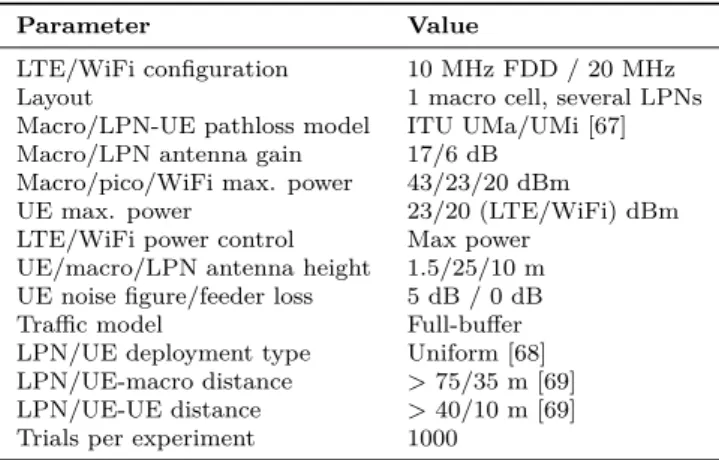
By varying the number of deployed LPNs, the cell density of the considered scenario is controlled. Below is an explanation of the basic LTE RA principles needed to understand the problem statement. The core part of the LTE-RA process is shown in Figure 3.2, and the UE-eNodeB message exchange is shown in Figure 3.5.
Within the preamble, UE then sends a specific ID, which eNodeB will also include in Msg 2 to acknowledge receipt of the Msg. In addition to the LTE-MTC Msg 1 overload scenario, the study also considered the limitations of Msg 2 capacity (which is tied to the number of Control Channel Elements (CCEs) allocated in Physical Downlink Control Channel (PDCCH)) and power consumption - explanation of the overall procedure. Finally, there is a brief discussion of the overload avoidance methods, which would apply in the mMTC scenario without necessary hardware modifications.
Simulation-based Environment
- Simulation Environment Comparison
- System Level Simulations
- Protocol level Simulations for LTE-based MTC
Technology-specific modeling tools are designed to evaluate the performance of a specific protocol stack or combination of multiple technologies in a specific environment. Designed to assess system-wide technology capabilities, SLSs are typically developed at the last stage of the risk management chain to approximate network performance under busy/congestion conditions and observe potential weak points that are not visible. in the prototype stage. LLSs are usually created in the early stages of development to get a realistic picture of P2P connection channels.
In the analysis, the traffic generator has been replaced with well-known distributions, where individual packets are not usually modeled. The event is indicated by any change in the simulated environment (such as data transmission, channel or mobility variation, or traffic arrival). It is also used to test upcoming releases of the standards under development, such as 3GPP mmWave NR [77] and analyze newly standardized architectures such as LWA and LWIP (both described in the previous chapter).
![Figure 3.4: SLS and analytical framework comparison, [4]](https://thumb-eu.123doks.com/thumbv2/9pdfco/1890881.267047/34.748.138.661.300.729/figure-sls-and-analytical-framework-comparison.webp)
Analytical Framework
- Resource Allocation in Three-Tier multi-RAT Network
MTC-enabled LTE
The analysis of the RA procedure in massive-MTC is divided into two parts: studies on congestion control performance and RA energy efficiency research. Congestion performance analysis begins by calculating the average time required to complete the RA procedure. The collision-free analysis only considers the power gain effect and gives the average time needed to process messages 1-2 for a single UE system.
The modeling of collisions is performed with the abstraction of memory effects and is based on the two-state Markov chain, shown in Figure 3.7, where states represent the number of pending user requests, while the transitions show the probability of new service request (Π ) arrival and successful message 1 -2 reception (˜µ). Analytical framework 27 In addition to the average service time in studies presented in [P5], there is also a description of the probability of RA procedure failure that occurs if the maximum number of preamble transmission attempts is reached (see Table 3.2). Under these conditions, the inactive period can last up to several seconds and will therefore affect the device's total power consumption.
MmWave Network
Instrumentation and Methodology is based on the correct distance and does not take into account the strength of the received signal, as is usually done in conventional cellular networks. Assuming that handovers are not allowed, the ergodic capacity of the UE session can be calculated as . This assumes that the UE is always connected to the nearest AP,pA,1 (proportion of time) when the LoS is not blocked and w1 is the probability that the blocking does not last longer than the transmission session.
Therefore, if the connection selection is based only on the distance between UE and AP, the UE can be completely blocked during the entire session with probability 1−w1, the value of which is linked to the blocking geometry, population density and relative UE- AP height [73 ]. The second connectivity strategy (Figure3.8, B), referred to in [P7] as "static, LoS AP" is based on the signal strength, which allows UE to avoid blocked connections, although handovers between different APs are still not allowed. However, in practical mmWave systems, handover duration depends on the beam search procedure speed, and thereby the overall performance is also linked to the appropriate protocol implementation.
4 Performance Evaluation
Selected Results
- Multi-RAT Network
- LTE-based MTC
- MmWave Network
Figure 4-2 shows the throughput equation of two chosen heuristic algorithms and the max-min fairness technique. As shown in Figure 4-9 (left, center), the high density of blockers significantly reduces the amount of interference received, especially for low AP density implementations. At the same time, the number of antenna elements (Figure 4.9, right) has no influence on the interference level.
It has also been noted that average throughput directly depends on the number of antenna array elements, as shown in Figure 4.10 (throughput values are calculated per one Hz bandwidth). In figure 4.11, the ergodic capacity of three different connection strategies (see subsection 3.3.3) is shown. Moreover, the optimal value of AP density was observed in the left plot of Figure 4.11 for all three schemes.
![Figure 4.2: Resource allocation strategies performance comparison [P1]](https://thumb-eu.123doks.com/thumbv2/9pdfco/1890881.267047/45.748.179.523.395.667/figure-resource-allocation-strategies-performance-comparison-p.webp)
Trial Activities
- Single UE Tests
- Test Network Infrastructure
- Multi-purpose Automated Vehicular Platform
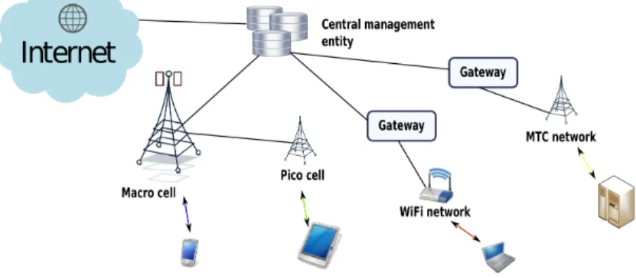
In the next step, a test network using multiple RAT LPNs was deployed on the TUT campus (Figure 4.13). To test the distributed network capabilities for MTC-related traffic, two versions of the automated vehicle platform were developed, as shown in Figure 4.14. The first version of the platform is equipped with two low-power electric motors used for driving and steering, two cell lithium polymer batteries, a custom motor controller and a raspberry pi 3 model with an integrated WiFi interface and LTE dongle.
The platform is connected to the application server through both LTE and WiFi RATs, using the connection scheme shown in Figure 4.12. On the application side, GUI was developed which enables the operator to obtain real-time video from the camera and control the platform using a keyboard. The second version of the platform (Figure 4.14, right) is equipped with more powerful chassis, camera and sensor subsystem, along with advanced single-board processing unit, which allows fully unmanned vehicle operation and the ability to connect 5G mmWave transceivers.
![Figure 4.12: Single UE test prototype implementation architecture [P3]](https://thumb-eu.123doks.com/thumbv2/9pdfco/1890881.267047/52.748.109.685.79.293/figure-single-ue-test-prototype-implementation-architecture-p.webp)
5 Conclusion and Potential Enhancements
HetNets Applicability Discussion
HetNets as Part of 5G
Nevertheless, both density and latency requirements can be satisfied using the ultra-dense HetNets concept; where multi-RAT amplifiers deployed widely in the coverage area provide sufficient user plane delay and capacity and play the role of gateway units for mMTC devices.
6 Summary of Publications
Publications Description
Finally, at the end of the publication, we also propose the prototype architecture of the demo network based on the solution that is then developed and tested by our research group. At the end of the publication, we also extend the prototype architecture initially proposed in [P2]. At the end of [P4] we also study the influence of hysteresis on the performance of the proposed inter-RAT transfer schemes.
The performance evaluation of the RACH congestion scenario is based on several criteria, including preamble collision and access success probability, total random access procedure delay, and energy consumption. This article is the result of the collaboration of the author and his supervisor with Vitali Petrov, Olga Galinina and Dr. This publication further develops the analytical framework and allows us to estimate the level of disruption and system performance.
Author’s Contribution
Summary of mmWave publications Specific system parameters, related to channel and antenna design, that are necessary to capture the essential differences of mmWave-based wireless communications when compared to conventional cellular deployments (operating at frequencies below 6 GHz). Finally, we evaluate the performance of three user connectivity options, assuming different AP, jammer, and antenna configurations.
Bibliography
Andrews, "Offloading in Heterogeneous Networks: Modeling, Analysis, and Design Insights," IEEE Transactions on Wireless Communications, vol. Wang, “IEEE Standard 802.16: Technical Overview of the WirelessMAN/sup TM/air Interface for Broadband Wireless Access,” IEEE Communications magazine, vol. Kunz, “Hardware-Type Communications in 3GPP Networks: Potential, Challenges, and Solutions,” IEEE Communications Magazine, vol.
Novlanet al., “Licensed Unlicensed Spectrum Access in LTE Release 13,” IEEE Communications Magazine, vol. Wang, “Heterogeneous Cloud Radio Access Networks: A New Perspective for Improving Spectral and Power Efficiency,” IEEE Wireless Communications, vol. Wang, “System Architecture and Key Technologies for 5G Heterogeneous Cloud Radio Access Networks,” IEEE Network, Vol.
![Figure 2.4: LWA architecture for collocated (left) and non-collocated (right) cases, [1]](https://thumb-eu.123doks.com/thumbv2/9pdfco/1890881.267047/22.748.161.652.377.499/figure-lwa-architecture-collocated-left-collocated-right-cases.webp)
![Figure 2.5: LWIP architecture, [1]](https://thumb-eu.123doks.com/thumbv2/9pdfco/1890881.267047/23.748.118.587.78.547/figure-lwip-architecture.webp)
![Figure 2.8: LPWA classification, [3]](https://thumb-eu.123doks.com/thumbv2/9pdfco/1890881.267047/25.748.123.578.422.750/figure-lpwa-classification.webp)
![Figure 3.2: LTE RA procedure details [P5]](https://thumb-eu.123doks.com/thumbv2/9pdfco/1890881.267047/30.748.150.654.118.491/figure-lte-ra-procedure-details-p.webp)
![Figure 3.3: mmWave network deployment details [P7]](https://thumb-eu.123doks.com/thumbv2/9pdfco/1890881.267047/31.748.69.634.685.886/figure-mmwave-network-deployment-details-p.webp)