The measurements of the antenna radiation pattern were carried out in collaboration with the author and Mr. the author designed and simulated the holograms and measured the manufacturing accuracy of the holograms.
Scientific research at submillimeter waves
At submillimeter wavelengths, however, there are only a few useful windows where transparency is reasonable: around frequencies and 850 GHz. Because of this limited atmospheric transparency, submillimeter wavelength astronomical observations must be made from very high-altitude platforms, such as mountaintops, airplanes, and balloons, where the water vapor content is low.
![Figure 1.1: Computed atmospheric opacity as a function of frequency for a 1 km horizontal test path through moist air [37].](https://thumb-eu.123doks.com/thumbv2/9pdfco/19350658.0/20.892.258.632.507.882/figure-computed-atmospheric-opacity-function-frequency-horizontal-moist.webp)
Submillimeter-wave antenna testing
The surface of the reflector must be precisely shaped to avoid side loops and deformation of high beam, which degrades the measurement accuracy. Usually, these reflectors, together with their feed systems, represent the latest technology, and therefore the manufacture of these antennas is very demanding, which increases the risk of errors [48, 59].
Scope and contents of this thesis
New scientific results
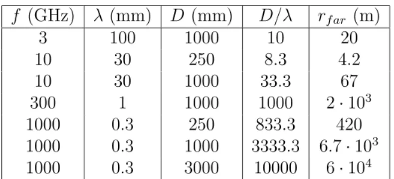
The nature of the electromagnetic field surrounding the antenna strongly depends on the distance from the antenna. In the vicinity of the antenna is the reactive zone of the near field, where the components of the reactive and non-radiative field predominate. The reactive power associated with this field does not propagate away from the antenna, but oscillates in the vicinity of the antenna.
The near-field radiation region is dominated by the radiation field components, and the angular distribution of the field depends on the distance from the antenna. The antenna (radiation) pattern represents the radiation characteristics of the antenna as a function of spatial coordinates.
Antenna measurements
Far-field method
In this case, the characteristics of the receive mode and the transmit mode differ, so the antenna must be tested in the same mode in which it is to be used. Near water absorption lines, under normal tropospheric conditions, atmospheric attenuation can reach tens of thousands of decibels per kilometer, which definitively rules out far-field measurements at those frequencies.
Near-field method
The near-field measurement area must be larger than the antenna aperture to ensure that all essential radiation emitted by the AUT is included in the far-field transformation. Near-field samples must be collected with a density that satisfies the Nyquist criterion, i.e. the distance of two adjacent sample points must be less than λ/2 in a rectangular planar geometry. Due to the large number of samples required, measuring the near field of large submillimeter wave antennas can be very time-consuming and take several days.
In these methods, phase retrieval algorithms are used to find the phase of the near field from the measured amplitude data [79, 80]. However, the measurement system requires very high stability and accuracy, making near-field measurements very challenging.
Compact antenna test range
Otherwise, the data is labeled, which reduces the valid angular range of the far-field data [ 70 , 76 ]. The radiation pattern of the probe antenna must be taken into account in the far-field transformation, for which purpose special probe compensation methods have been developed [70]. In addition, by using a dual or triple reflector configuration, the planarity and size of the quiet zone can be significantly increased.
In the dual and triple reflector CATRs, edge diffraction can be reduced by focusing the main reflector illumination toward the edges. Therefore, the main reflector of the CATR must be clearly larger than the AUT.

Hologram design
Binary transmission function
In the phase holograms, the effective electrical thickness of the hologram structure is locally varied, causing the desired phase modulation [13, 18]. In the previous formulas, A(x0, y0) is the amplitude modulation, Ψ(x0, y0) is the phase modulation, and (x0, y0) are the coordinates in the plane of the hologram. If the target field is a plane wave, ψ(x0, y0) is the normalized phase of the incident field.
The amplitude of the transmitted field can be increased (decreased) by widening (narrowing) the passages locally according to the weight function aw(x0, y0). Accordingly, the phase of the transmitted field can be shaped by tuning the slot locations according to the additional phase term ψe(x0, y0).
Hologram optimization
A local change in the transmitted field mainly affects the local quiet zone field, making optimization of the CATR hologram fairly straightforward. An oblique propagation angle decreases the width of the quiet zone in the horizontal direction. It has been found that the hologram works better when the variation of the grating periodicity is reduced.
To redirect the illumination, the feed must be turned from the angle α towards the center of the hologram. A typical phase deviation is such that it can be compensated by adjusting the supply location slightly.

Electromagnetic simulation
Two-dimensional FDTD simulation
The numerical dispersion results from the discretization of the simulation domain and causes variation of the numerical phase velocity with wave propagation angle [98]. The numerical phase velocity is always smaller than the physical phase velocity of the wave. In this way, the locations of the slot edges and the field in the vicinity of the edges are modeled more accurately.
Using larger cells further from the crack edges helps to keep the computational size of the simulation reasonable. The simulation domain is very wide in the x direction (up to hundreds of thousands of FDTD cells) but quite narrow along the thez axis (approximately a hundred cells).

Excitation
The cross-polarization analysis is not possible in the two-dimensional simulations, where the curvature of the slots, and thus the source of the cross-polarization, is omitted; a special method to analyze cross-polarization is presented in [101]. The simulation domain is surrounded with an absorbing layer that serves to simulate the radiating free-space condition. When the excitation is turned on slowly during the first 4.5 sine wave cycles, no DC field components can be observed in the simulation data.
Physical optics
Manufacturing
The maximum area that can be processed with this facility is 1.2 m × 3.2 m, and the nominal accuracy of the laser writing is 5 µm. A low permittivity is desirable to minimize the effect of the dielectric film on the propagation of the electromagnetic wave. Since the copper skin depth is very small at submillimeter wavelengths, even a thin copper layer almost completely blocks the transmission of the wave.
To avoid discontinuities in the hologram pattern, the pieces must be carefully aligned and joined using a method that does not interfere with the propagation of the electromagnetic wave. At submillimeter wavelengths, taping and gluing significantly increase the electrical thickness of the substrate, causing distortion of the quiet zone field.
Properties of the hologram as a collimator
Non-idealities in the CATR and their effect
Distortions in the quiet zone field and their influence on antenna measurement results were analyzed. When the hologram was later simulated with a denser grid, there was a 0.5 dB drop in amplitude in the quiet region field. Systematically too narrow slits have been observed to cause a drop in amplitude in the quiet region field when the hologram pattern is designed to illuminate the horn (for example, see the quiet region simulation results in [VII]).
Since the imperfections in the quiescent field were quite large, it was necessary to evaluate their influence on the measured radiation pattern of the antenna. In addition, amplitude and phase ripples in the quiescent field and reflection from the surroundings can cause lateral sidelobes.
Hologram as a reflection-type collimator at 310 GHz
In the reflection-type setup, the location of the feed was a mirror image of the transmission-type setup. To eliminate the transmitted field, an absorber wall was placed behind the hologram in the reflection-type setup. The power loss was also measured: the quiet zone amplitude level was compared to the maximum amplitude level of the horn illumination in the hologram aperture.
In this way, the power loss was calculated to be approximately 11.4 dB in the transmission type arrangement and 7.4 dB in the reflection type arrangement. The radiation pattern measured in the reflection setup corresponded well with the pattern measured in the transmission setup.
Hologram-based CATR at 650 GHz
In the transmitted plane wave, the measured peak-to-peak ripples were 1.2 dB and 10◦ , and in the reflected plane wave, they were 1.6 dB and 20◦ . The phase of the reflected plane wave was slightly convex, apparently due to a slight distortion of the supply. The reflection-type configuration was also used to measure the radiation pattern of a small lens-type antenna [109].
According to these experiments performed at 310 GHz, the flatness achieved by tightening the hologram on a frame is sufficient even for reflection type operation. Excluding the systematic manufacturing error, the random manufacturing error in the slit widths was measured to be only ± 5 µm in the hologram produced on the 50 µm Mylar film.
Dual reflector feed system
This chapter introduces the Dual Reflector System (DRFS) and discusses its use for hologram illumination. In publications [VII–IX], simulations and experiments have shown how hologram characteristics can be improved using DRFS for illumination. This is desirable because the ripple in the DRFS beam directly increases the total ripple in the quiescent field.
The DRFS is designed to illuminate 600 mm diameter holograms from a distance of 1.8 m; the beam width of the –1 dB illumination is 370 mm, and the edge illumination is approximately –15 dB. DRFS can also be used for holograms of different sizes as long as the relative focal length remains roughly the same.
Improved manufacturing properties
According to measurements, the actual DRFS radius differs only slightly from the ideal one [VII].
Operation at the horizontal polarization
Operation at the circular polarization
Reduced cross polarization
R¨ais¨anen, “Fabrication of large amplitude holograms for a submm-wave CATR,” in Digest of 2002 IEEE Antennas and Propagation Society International Symposium, vol. R¨ais¨anen, “Synthesis of a dual reflector feeding system for a hologram CATR,” in Digest of 2002 IEEE Antennas and Propagation Society International Symposium, vol. H¨akli, “A compact RCS range based on a phase hologram for scale model measurements at submm wavelengths (invited plenary lecture),” in Proc.
20] ——, “A compact RCS range based on a phase hologram for scale model measurements at submm wavelengths (invited plenary lecture),” in Proc. R¨ais¨anen, “Feasibility study of a hologram-based compact antenna test range for 650 GHz,” in Proc. Lemanczyk, “Mm and sub-mm wave hologram based compact antenna test ranges used for testing electrical antennas,” in Proc.
R¨ais¨anen, “Hologram-based compact arrays for antenna and rcs testing at submm waves,” in Proc.