According to the lumped mass theory, internal bending and torsional moments due to balanced forces of the engine do not excite the rigid body modes. The aim of this thesis was to find out whether the internal bending and torsional moments generate the rigid body modes in practice. Calculation software was used for the calculation of engine excitations and rigid body natural frequencies and mode shapes.
Operating deflection shape corresponds to rigid body motion when the natural frequency is tuned close to the excitation frequency.
INTRODUCTION
The calculation section covers the modeling of the rigid body modes of the flexibly mounted motor and the calculation of the motor excitation forces. In addition, the procedure for weighing the engine and calculating accurate mass properties for the rigid body model is presented. Finally, the measurement results are presented and analyzed to construct answers to the research question.
THEORY
Basic vibration mechanics
- Free vibration
- Forced vibration
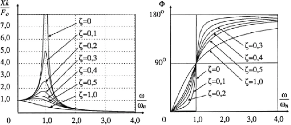
- Frequency response function (FRF)
- Amplitude
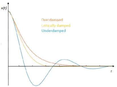
This results in large vibration amplitudes in motors when the excitation frequency of the motor and the natural frequency of the structure match [13]. The frequency response of a system means the frequency-dependent response of the system oscillation to the excitation applied to the system. The frequency response function of the system can therefore be obtained by measurement. system response and excitation force.
For both graphs, the horizontal axis is the ratio of the excitation frequency ω to the natural frequency ωn of the system.
Flexibly mounted engine
- Dynamics of rubber elements
- Calculation software for rigid body modes and system response 10
- Mass forces of a crank mechanism
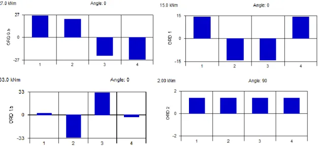
- External forces and couples
- Internal bending
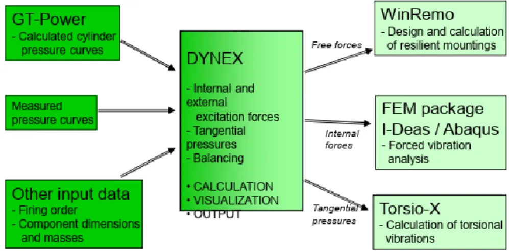
- Gas forces (internal and external excitations)
- Excitation calculation software
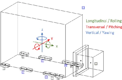
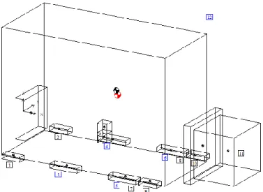
The directions of the 6 rigid body modes; 3 translation and 3 rotations are presented in the figure. The rotating masses are the crank, the rotating part of the connecting rod and the counterweight. 𝐹𝐴,𝑣= −𝑀𝐴𝜔2𝑟𝑐𝑜𝑠𝜔𝑡, (2.31) where ω is the angular velocity of the crankshaft and r is the length of the crankshaft.
The extra mass in the flywheel can be replaced with a hole on the other side of the flywheel.
MEASUREMENTS
- Equipment
- Accelerometer
- Analyser / recorder
- Hydraulic shaker
- Measurement methods
- Operating deflection shape (ODS)
- Speed sweep & stop
- Performing the measurements and making measurement settings
- Test matrix
In Table 1 are some key specifications of the used Kistler Type 8762A50 accelerometer according to the data sheet. Some of the key specifications of the Kistler Type 8762A50 sensor used in the vibration measurements in this work. As previously described, the frequency response function of the system can be determined by measuring the excitation force and the vibration response.
Therefore, the true FRF of the system can be formed from the shaker measurement data. ODS differs from mode shapes in that the motor excitation shapes are also included in the response, while mode shapes depend only on structure properties. Traverse and stall measurements are performed to determine the motor's natural frequencies and vibration amplitudes in resonant situations.
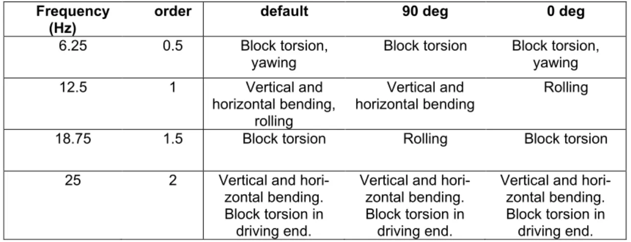
As explained earlier, the excitations occur at multiples of the motor speed (harmonic orders). The frequency of the motor excitations on the harmonic orders increases as the motor speed increases, which can be noted as low, angled ridges on the xy plane. The natural frequencies can be deduced from the shape of the peak (compare with the waterfall).
For the sweep and stop measurements, only 10 measurement points were taken: the corner points of the engine block A1, A3, C1, C3 and the point B1 on both banks. The signals and shaping of the sweep spectra were monitored during the entire sweep and stop.

CALCULATIONS
Mass and centre of gravity
Modelling of rigid body modes with WinRemo
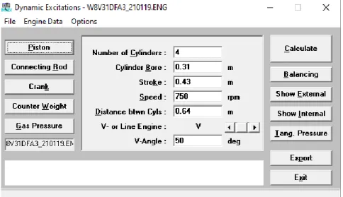
- Engine W8V31DF
- Engines W16V31 and W12V31
Inertia properties are constructed with Modal Model Method which fits the calculated rigid body modes to the experimentally measured changing inertia properties in WinRemo. The mass element of separate flywheel and vibration damper is removed from the model as mass values of the engine with flywheel and damper are obtained as the weighing results. The mass elements for the flexible mounting feet are left in place as they are not mounted to the weighbridge.
Mass characteristics of the flexible coupling are changed to match the Rato R+ G3E20 damper model along with PTO used in the test run installation. For the flexible mounts, both nonlinear XK-34X55/915 model found from the stiffness element library and dynamic stiffness values according to the Figure 32 as linear stiffness element are found. The dynamic stiffness values in the figure are measured while assembly preloaded by W8V31 engine.
For the non-linear element, the dynamic coefficient was changed to 1.9, which corresponds to the ratio in Figure 32, and also gave the best results compared to the measurements. The stiffness elements of the used exhaust bellows and flexible coupling are found in the WinRemo library. The visual model, input values and calculation results for the W8V31DF engine are in appendix B.
Up to this point, the model is accurate enough to relate its own frequencies to the measurement results. The mass properties of the flexible clutch have been modified to match the CX-186 shock model along with the long PTO shaft that was used in the test drive setup.
Engine excitations
RESULTS AND ANALYSIS
Rigid body natural frequencies
By combining this with animations generated from the data and comparing with calculated natural frequencies, the actual rigid body natural frequencies can be identified. ODS frequency response function of the W8V31 engine with the different flexible mounting configurations, obtained from the engine stall measurement. The rigid body natural frequencies obtained from the sweep and stop measurements below with the WinReMo calculated natural frequencies are listed in the Table 4 – Table 6.
Table 5 also contains the natural frequencies from the measurements of the shaker that were performed with and without oil in the engine. Measured and calculated rigid body natural frequencies (Hz) of the W8V31DF motor with the default flexible element configuration. Measured and calculated rigid body natural frequencies (Hz) of the W8V31DF motor with the 90 degree flexible element configuration.
They measured and calculated the rigid body natural frequencies (Hz) of the W8V31DF motor with the 0-degree flexible element configuration. From the tables, it can be noted that the natural frequencies have large differences between the flexible mount configurations, showing that the rigid body modes can be tuned really easily with the flexible mounts. The calculated translation modes agree well with the measurement results, which means that the stiffness values in the WinRemo model are fairly correct.
Sweep measurement is done much more slowly than stopping, and so the natural frequencies obtained with sweep should be more accurate with much higher resolution. The effect of oil in the engine on natural frequencies does not agree very well with the calculations.

Mode shapes
The working deflection form at order 1 (12.5 Hz) is mainly vertical and horizontal bending, also some roll. With the 0-degree configuration, the roll mode is at 12.4 Hz, just on order 1, and the roll motion is clearly dominant. In Table 8, the vibration amplitudes in sequence 1 with the different flexible element configurations are shown.
It can be seen from the table that the 0-degree configuration, which has the rolling mode at order 1, has the highest amplitude, and the 90-degree configuration, where the rolling mode is farthest from order 1, has the lowest amplitude. It is obvious that the roll mode at 12.4 Hz is excited to order 1 with the 0-degree configuration, although the shape of the excitation is different, and according to lumped mass theory, the internal bending should not excite the rigid body state. As mentioned, the roll mode with the 90-degree configuration is at 17.5 Hz, which is close to the order of 1.5.
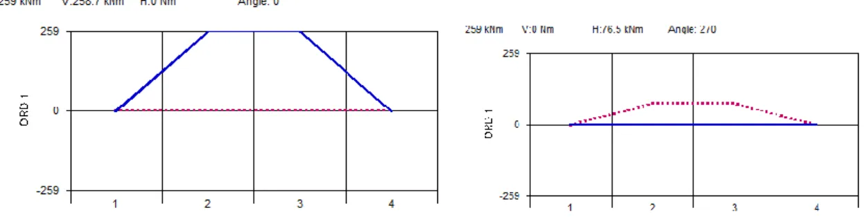
The same thing happens when looking at the vibration of order 1.5; the rotary mode shape dominates with the 90 degree configuration. The mode is excited from order 1 to the highest engine speed at standstill. In order 1 (12.5 Hz) the main excitations are the internal bending moment with an amplitude of 366 kNm in the vertical direction and 108 kNm in the horizontal direction (Table 3 Error! Reference source not found.).
The dominant mode shape of order 1 according to the ODS measurement is block bending. At order 0.5, the shape is a combination of slope and oscillation, as close to the order is the mode of oscillation.
CONCLUSIONS
The guideline should be considered in future measurements to obtain better starting values for rigid body calculations. WinRemo can also be used to calculate the dynamic response of the system by introducing external excitation forces into the model. The reason that rigid body modes are excited by internal excitations is that a large motor cannot be considered a perfect rigid body, so the natural modes, which are called rigid body modes, do not have an ideally rigid shape.
Since WinRemo assumes the rigid body and only external excitations can be input into the program for response analysis, it is necessary to study how much large amplitude external excitation is needed for the corresponding vibration response. In this way, by finding equivalent external forces for the internal forces, the fast and designer-oriented program can be used to calculate the response taking into account internal excitations as well. Afzal, Flexible Mounting System Design, Theory and Practice, Master of Science Thesis in Sound and Vibration, KTH, Stockholm, 2009.
Prediction of static response via non-linear analysis and response surface methodology, Ocean Engineering pp.14-24. 19] Annular Ceramic Displacement Sensor Lightweight, Stress Mode, Triaxial Accelerometer, Kistler Data Sheet, [Online], Available: https://www.kistler.com/files/document/000-456e.pdf?callee=frontend, cited 10/6/2022. Revealed!, Endaq blog, [Online], Available: https://blog.endaq.com/piezoelectric-accelerometers-how-they-work-and-where-to-buy, Cited 10/6/2022.
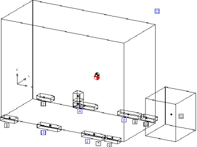
23] Guidance for evaluating inertial properties using frequency response functions (FRF) in large diesel engines, Wärtsilä Internal Document, 2021. Hanly, Vibration Measurements: Basics of Vibration Analysis, Endaq Blog, [online], available: https://blog.Endaq.com/Vibration-Masues-Vibrimi-Analiza-Basit, Citecs 10/6 Squares small and numbered are stiffness elements for the flexible assemblies (1-10), the flexible coupling (11) and the exhaust bottom (12).
![Figure 12. Typical crank stars and firing orders of different engine configurations. [25]](https://thumb-eu.123doks.com/thumbv2/9pdfco/1890327.266493/24.892.176.756.295.485/figure-typical-crank-firing-orders-different-engine-configurations.webp)
![Figure 25. Measurement equipment for the vibration measurements. (Adapted using the figure in [19])](https://thumb-eu.123doks.com/thumbv2/9pdfco/1890327.266493/32.892.170.786.389.719/figure-measurement-equipment-vibration-measurements-adapted-using-figure.webp)