A comparison of testing methods showed that model testing brings financial benefits to the organization. By using model-based testing, a lot of time has been saved in test execution compared to traditional testing methods.
INTRODUCTION
- O BJECTIVES
- S COPE
- M ETHODS
- S TRUCTURE
The model-based test tool will be implemented using Java based on the results of the literature study. The result of the comparison will ultimately decide whether it is worth continuing on the model-based test track.
MODEL BASED SOFTWARE ENGINEERING
- P ROBLEMS WITH THE C URRENT S TATE OF S OFTWARE E NGINEERING
- G ENERAL D ESCRIPTION OF A S OFTWARE M ODEL
- B ASIC M ODEL T YPES
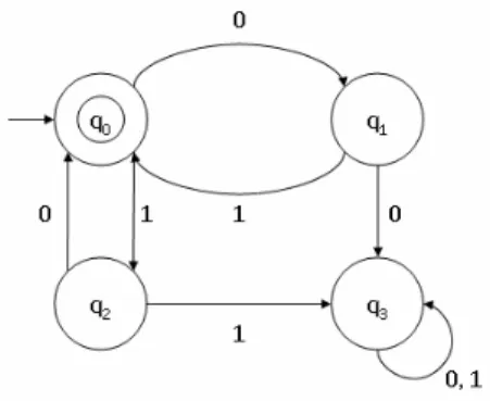
- Finite State Machines
- Markov Chains
- State charts
- Grammars
- The Unified Modelling Language
- D IFFERENT A PPROACHES TO S OFTWARE M ODELLING
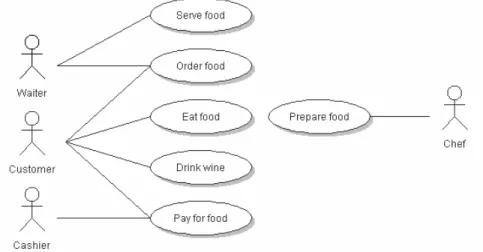
- Use Case Model
- Application Model
- C REATING THE M ODEL
- M ODEL B ASED T ESTING
- Benefits of Model Based Testing
- Difficulties and Drawbacks of Model Based Testing
- Currently Available Model Based Testing Tools
The basic idea of model-driven development is to automate the transformation of models from one form to another [12], which means that models are imported from one form, for example the previously described methods, and exported to another form; for example C source code. Other benefits more related to testing are e.g. the following, which were presented in [13]:.
DEPLOYMENT OF MODEL BASED APPROACH INTO AN ORGANIZATION
P ROPOSITION FOR A S TARTING P OINT
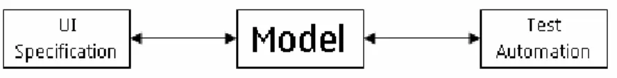
The exploitation requires that a tool is available that can transform UI specifications into an application model, and create test cases from it. It is also possible that the UI specifications will be written in such a way that the addition of the test automation parameter can also be automated using a text parser, but this will require a formal way to create the designs. One possibility to write the UI specifications in a formal form could be to make use of the use case document template presented in section 2.4.1.
In the case of the S60 UI, which contains several small applications, the design document must be divided into several smaller parts, consisting of the small applications, and into one higher-level document. The higher level, or main document, would describe the input and output of the small applications at a higher level of abstraction, and the other design documents the internal workings of the applications. The approach to the structure of the presented UI specifications would be formal enough for model building, and in addition to the formalism, the layered structure would also make the specifications easier to read, as the higher level would not contain too many details about the internal workings . of individual applications.
T HE F UTURE
For example, it is possible to access the messaging application from various other applications such as camera or image viewer. Because the statement presented is only a starting point, discussion about the future is also necessary. Of course, several questions arise when thinking about automatic code and test generation; Examples include whether the code is correct and sufficiently optimized, and whether the code coverage achieved with automatic test generation is at an acceptable level.
These questions are of course relevant and legitimate, but perhaps there is no reason to be concerned; as stated in [11], the questions of code correctness and optimization were already raised over 40 years ago when the first compilers were introduced. The same techniques currently used in compiling higher-level languages to machine code can be used to transform the model into high-level languages, and thus correctness or optimization are the least problems that model-driven development will face. The biggest problems are related to the actual implementation of the model-based approach in a large organization.
DESIGN AND IMPLEMENTATION OF THE MODEL BASED TESTING TOOL
R EASONS FOR I MPLEMENTING O WN T OOL
Of course, it must also be possible to create the model from scratch, without the need for existing documents or designs. A second important requirement is that the tool must support the generation of test cases as described in section 2.6, i.e. randomly generated test cases and test cases for which the model coverage is 100%. The third requirement concerns the graphical user interface of the tool and especially its usability.
The tool should be so easy to use that everyone involved in the software engineering process can easily learn how to use it and preferably not even need to read the manual. of use in advance.
I NTRODUCTION TO T EST A UTOMATION S YSTEM
Based on the results of the validation keywords, ASTE sets the test case to pass or fail.
P REVIOUS W ORK
A log is also written in HTML format, where the errors can be viewed in a user-friendly format. As the listing shows, the previous version only supported use case models (section 2.4.1), and application models were not supported at all. Use case models were not allowed to contain loops, and the test case generation was therefore performed with a simple but appropriate depth-first search (DFS) algorithm.
Many of the features implemented on the tool during this work are based on the future improvement suggestions in [8]. The previous version was a good starting point for this work, but this version was designed and implemented completely from scratch.
H IGH - LEVEL D ESIGN
- The Model
- File Input and Output
- Test Case Generation and Execution
- Graphical User Interface
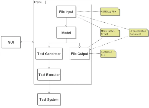
For example, every single part of the tool can be easily changed to another because the parts are not tied together too deeply. Different parts of the architecture visualized in Figure 11, that is, the model, file import and export, test case generation and execution and the GUI, are presented next. As seen from the picture, the model consists of name and general description of the model, before and after states (in which state the system should be when the execution of the model starts or stops), test data and a graph which used as a data structure to store the actual finite state machine.
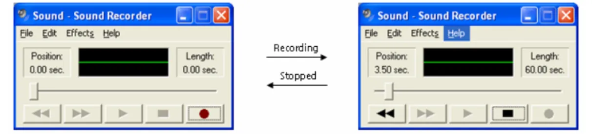
For example, in the S60 Voice Recorder application it is possible to change the quality of the recording to high or low. The format of the UI specifications should be the use case document template presented in section 2.4.1. The tool's users can be narrowed down to two groups: UI designers and testers.
T HE I MPLEMENTATION : KENDO
- Test Case Generation Techniques
- Graphical User Interface
The GUI uses 6000 lines of code, which contains e.g. the normal windows, file trees, toolbars and menus and the graph component. The implementations of the test case generation and the graphical user interface are presented next. In these cases, the interfaces were taken from the previous version, but all functionality was rewritten from scratch for this version.
If there is more than one exit transition in the list of transitions, select one of them using the random number generator and exit transition probabilities, go to the event that the randomly selected transition leads to, and go to 2). As can be seen, abstraction hides many details and improves the readability and usability of the model. The most important parts of the design panel are the graph editor located in the upper right part of Figure 21 and the event editor in the lower right part.
F UTURE I MPROVEMENT S UGGESTIONS
When user selects an event in the graph editor, its properties are opened in the event editor. The description, test automation and flag editors are separated to different tabs in the event editor. In addition, the problem with state space explosion described in section 2.6.2 should be studied more and this part of the tool should be improved.
ANALYSIS
C OMPARISON TO P REVIOUS W ORK
- Differences to the Previous Work
- Advantages of the Current Tool Implementation
The approach used in this thesis is more in line with the ideology of model-based testing than the use case approach used previously. With 100% model coverage, it is possible to compare the code coverage achieved by model-driven testing with the coverage achieved by manual tests, and thus gain knowledge about whether or not a model-driven approach has advantages over traditional testing methods . To reduce state space explosion, which is one of the biggest problems of model-based testing, as described in Section 2.6.2, flags were added to the model.
The changes in this version allow the use of the full potential of model-based testing, unlike the previous version, which was basically a helper for creating use case-based test cases. Additionally, some of the added features aim to reduce the state space explosion problem, which may prove to be a valuable feature in the future. The next section aims to prove that model-based testing is a technique that brings financial benefits to an organization if its full power is unleashed.
C OMPARISON B ETWEEN T ESTING M ETHODS
- Used Test Metrics
- Test Environment
- Results
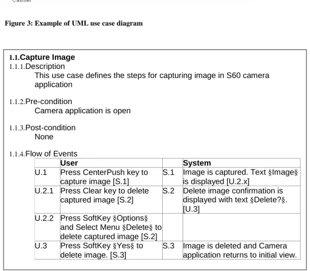
The use cases contain test goals ("Test if an image opens correctly"), required test data ("One image of any supported image format"), prerequisites ("One image is available on the phone"), and implementation steps that contain a description of what to do ("Open image") and what the expected result is ("Image opened correctly"). This means that more application code is run with use case-based tests, since the model is just a representation of the UI functionality. It is also significantly faster; in the case of the image viewer, almost the same code coverage was achieved with 8 hours of automated testing as with 48 hours of manual test execution.
Model-based testing is also a clear winner in terms of man-hours used to initiate testing. The annual figure for model-based testing does not include model maintenance; nor can it be estimated, as very little experience has been gained on the subject. The calculations above show that using model-based testing, approximately over a thousand man-hours would be saved per year in the case of the Image Viewer.
CONCLUSIONS
- R ESULTS
- A SSESSMENT OF R ESULTS
- E XPLOITATION OF R ESULTS
- F UTURE R ESEARCH
The promising results obtained in the comparison of test methods should be a clear signal to the organization that the model-based approach should be exploited even more, and that time and money should be invested in it. Currently, it does not seem possible to deploy the model-based approach to the organization with the starting point proposed in Chapter 3, which uses the user interface specifications as a basis for the model creation. Another reason for the problems with the implementation of the model-based approach is the lack of productization of the KENDO tool implemented in this work.
The difficulties are a shame, because in this work the model-based approach was shown to bring benefits to user interface level testing, and the only thing missing was sufficient formal user interface specifications from which the models could be imported . For example, module design and testing appear to be too complex to integrate into the model-based approach. Why model-based test automation is different and what you need to know to get started.