Furthermore, a concept for a new type of periodic leaky wave antenna based on the NRD guide is presented, where high impedance surfaces allow the radiated electromagnetic wave to propagate out of the waveguide structure. The knowledge of the propagation constant of the NRD conduction mode of operation is crucial for the design of periodic leaky wave antennas. The prototype of the transition was then used for measuring the radiation characteristics of the NRD guided end-fire antenna.
Therefore, the experimental end-fire antenna was measured in the department's anechoic antenna room.
WAVEGUIDES
Basic principles
- M AXWELL ’s equations
- Standard metal waveguides
- Dielectric rod waveguides
- Non-radiating dielectric waveguides
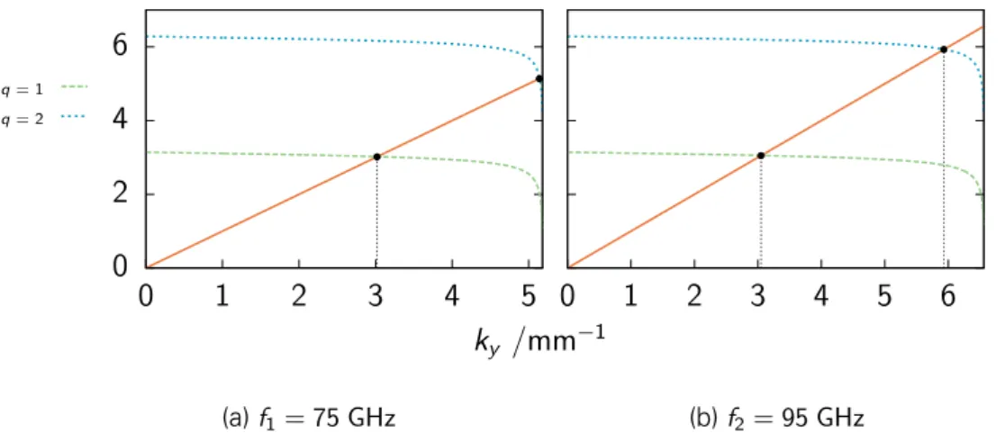
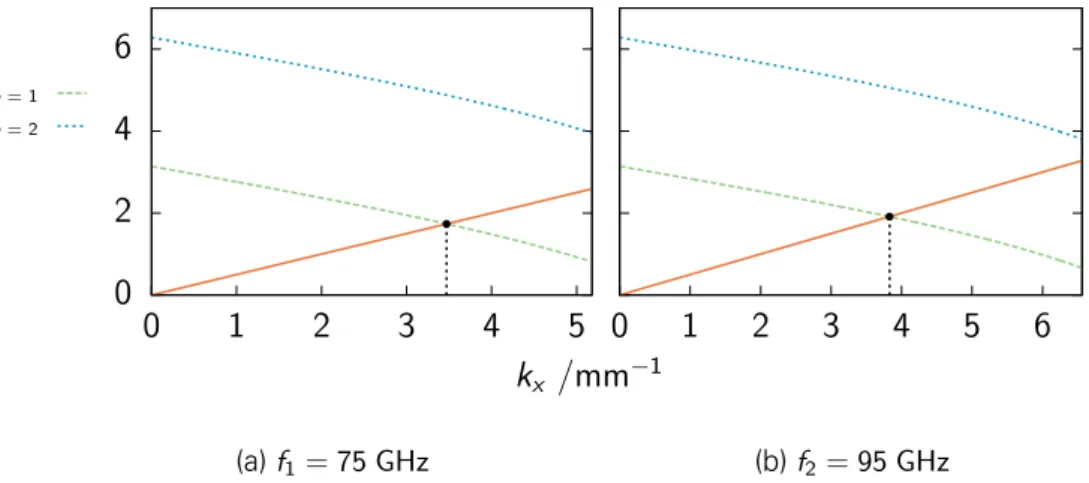
To obtain the relation for the wavenumber components of the propagating wave, the HELMHOLT equation is calculated for either the electric or magnetic field. For the TE10 mode (the distribution of the electric and magnetic field is shown in Figure 2.4a), the electric field in the waveguide has the form shown in Figure 2.4b. The upper letters x and y indicate the strongest component of the electric field [9] in that state.
The main advantage of the NRD bus is the radiation-free behavior outside the dielectric strip between the metal plates, where the spacing is less than half a free-space wavelength and the limit state is reached.
NRD guide model
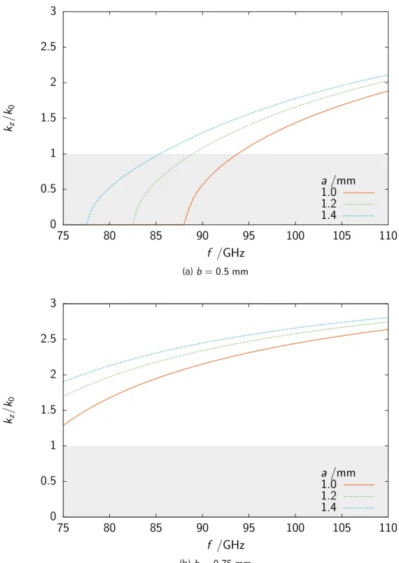
The dispersion diagram skz/k0−f for the classical NRD guide meda =d is shown in Figure 2.13 and A.1 for different values of the dielectric rod height deb. It is also possible to derive the propagation constant kz and the guide wavelength λg analytically from the simulation results as described in Appendix D.
M ARCATILI ’s method for non-radiating dielectric waveguideswaveguides
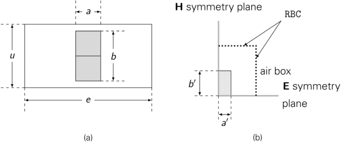
Finally, the transverse components of the electric and magnetic field can be expressed by the longitudinal components Ez and Hz as. In MARCATILI's method, the transverse components are estimated by considering vertical and horizontal dielectric plate waveguides [22]. CATILI's method embedded between parallel metal plates (refer to Figure 2.9c) with width a= 2a�and distance from the metal plates d = 2d�.
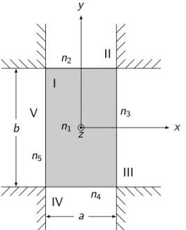
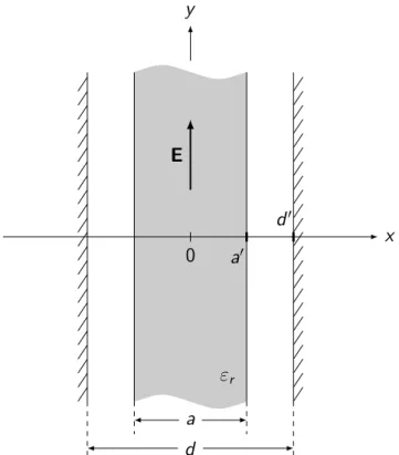
Vertical dielectric slab waveguide embedded between parallel metal plates
Furthermore, the assumption that the field distribution does not depend on the vertical coordinate and thus ky = 0 reduces equation (2.40a) to. For the wave propagation in the air-filled region, a� < x < d� equation (2.40a) leads in a similar manner. However, if a cosinusoidal distribution is taken into account, this adds a phase difference of π2 to equation (2.49).
For the special case a = d – which depicts the classic NRD guide as shown in Figure 2.9a on page 13 – the coefficient C becomes zero and therefore equation (2.77) simplifies to the familiar equation.
Horizontal dielectric slab waveguide
M ARCATILI 1.0
Comparison of the numerical simulation results and M ARCATILI ’s approximation method
M ARCATILI 1.4
M ARCATILI 1.0
- Standard metal waveguide to NRD guide transi- tiontion
- Design
- Simulation results
- Measurement results
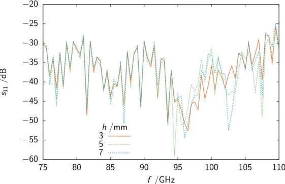
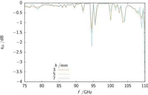
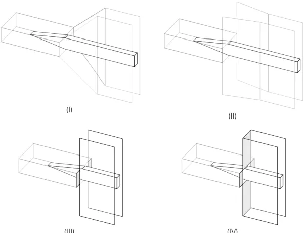
The dimensions of the NRD guide, the rectangular waveguide (WR-10 standard for 75 to 110 GHz) and the tapered section of the dielectric rod are given in Figure 2.28. While the NRD guide is attached directly to the rectangular waveguide for types (III) and (IV), a variable-length transition section is placed between the two waveguides for types (I) and (II) and the effect of length on the reflection and transmission properties was studied. The leakage from the NRD bus is affected by the height of the side walls, so its influence on the transmission characteristics was studied.
The cross-section of the NRD guide in the HFSS simulation models for the transition is shown in figure 2.12a on page 15. For the reflection coefficients21dB|(III) it can be seen from figure 2.31 that for h = 3 mm leakage out of the NRD guide occurs for lower frequencies, whereas for frequencies higher than f ≈ 100 GHz, s21 decreases again. The junction chosen is junction type (III), where the two waveguides are attached to each other directly with a tapered dielectric rod (Figure 2.32 shows a schematic model of the NRD guide with two junctions).
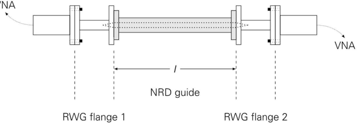
For the experimental verification of the simulation results of the transition, two aluminum sidewalls with appropriate connections for the standard metal waveguide segments were produced. The cross section and the top view schematic diagrams of the experimental NRD guide are shown in Figures 2.36 and 2.37 on page 50. This setup formed the device under test (DUT) connected to the test port connections of the HP8530Avector network analyzer (VNA). Figure 2.38 shows a picture of the DUT in the test measurement setup.
Since the setup consisted of a highly experimental NRD conductor with a narrow dielectric rod, it can be seen from the cross-section and top view that the correct symmetrical placement of the NRD conductor sidewalls relative to the RWG flanges and the dielectric rod between the sidewalls and the metal waveguide by hand was a challenge. Analysis of the transmission coefficients21 in Figure 2.40 shows the poor transmission characteristics of the composite NRD guide for frequencies below ~80 GHz.
WAVEGUIDE ANTENNAS
Basic principles
- Antenna parameters
- Leaky-wave antennas
- High impedance surfaces
By definition, the main propagation direction of the simulated antenna structures is set as their direction. To be suitable as a uniform leaky-wave antenna, the dominant mode must operate in the fast-wave region (vph >c), so its phase constant β must satisfy the condition. where k0 is the wave number in free space. After deriving the phase constant β and attenuation constant α of the guiding structure, the beam angle θm and beam width ∆θ can then be calculated using simple equations.
L/λ0) cos (θm) (3.12), where θ is measured perpendicular to the direction of propagation inside the guide structure (Figure 2.2 on page 6 illustrates the coordinate system used with the wave traveling along the z-axis in the waveguide). However, this only works if the phase constant of the dominant mode of propagation operates in the fast-wave range and fulfills equation (3.10). The parameter d, which indicates the distance between the parallel plates, is continued over the dielectric, then controls the leakage of the antenna.
Explained differently, in a periodic structure formed by discontinuities, Floquet spatial harmonics appear, and some of them may be in the fast-wave region. The spatial harmonics are caused by reflection of the incident wave at the discontinuities. This causes strong reflection for the given broadband radiation frequency and a strong attenuation of the propagating wave in that stopband.
If the period of the surface texture defining the unit cell is much smaller than the wavelength of the desired frequency, the structure can be described by the surface impedance [38]. The size of the unit cell defines the frequency for which it acts as a high-impedance surface. 2008) introduced a high impedance voltage controlled surface for the W frequency band [39].
![Figure 3.3: Near-field and far-field region surrounding an antenna with diameter D [30]](https://thumb-eu.123doks.com/thumbv2/9pdfco/19373575.0/65.892.235.666.139.548/figure-near-field-field-region-surrounding-antenna-diameter.webp)
NRD guide end-fire antenna
- Design
- Simulation results
Similar to the simulated NRD guide model in Section 2.2, it is possible to reduce the simulation time of the simulation model by exploiting the electric and magnetic symmetry of the NRD guide. Since the height of the metal plates has an influence on the radiation patterns, the variation of the height from 3 to 9 mm with a step size of 2 mm was investigated. Since only a conceptual model of the NRD guide end-fire antenna is presented in this research, the radiation efficiency of the antenna was not investigated and the dielectric rod was considered to be lossless.
The maximum gain G0 listed in Table 3.1 varies with the height of the metal plates and with frequency. For h3 = 7 mm, the effect of extending the metal plates halfway over the edge of the radiating cone, s = 3 mm, was studied. Looking at the plot of peak gain G0 versus frequency in Figure 3.10, the effect of the height of the metal plates can be seen.
For h = 9 mm, the antenna provides maximum stable gain G0 ≈ 9.5 dB for all three studied frequencies.

NON-RADIA TING DIELECTRIC W A VEGUIDE ANTENNA SG/dB
- Measurement results
- NRD guide leaky-wave antennas
- Design
- Simulation results
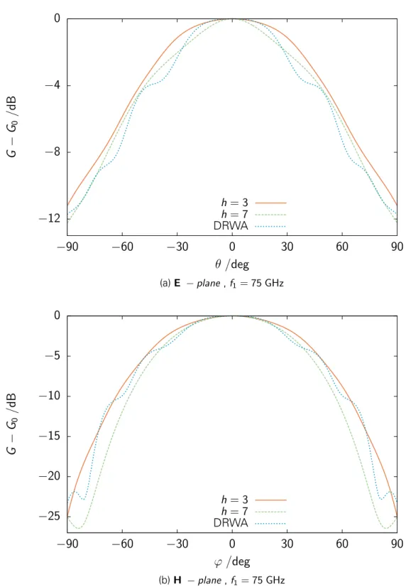
For measuring the far-field radiation patterns of the NRD conductor-end-fire antenna, a planar scanner from Nearfield Systems Inc.1 (NSI) was used. The correct placement of the dielectric rod inside the waveguide could not be verified due to the experimental assembly. Evaluation of the H-plane radiation pattern in Figure 3.18, corresponding to the horizontal movement of the scanning unit in the x-direction, reveals the asymmetric placement of the dielectric rod in the NRD guide.
The comparison of the E-plane radiation pattern in Figure 3.19 also shows the asymmetric position of the dielectric rod and the NRD guide as a whole. This may be caused by the collection of the experimental NRD guidance and inaccuracies in the measurement setup. The discontinuities were modeled as flat PEC planes placed on top of the dielectric rod.
Shortening the length of the stubs to = 0.5 mm leads to the radiation pattern in the E-plane as shown in Figure A.23. In Figure 3.26 the beam angle θm from the simulation results is compared with the calculated beam angle. This, and the change in the propagation characteristics of the NRD guide through the discontinuities, explains the beam angle shift.
The effect of the shape and size of the logs (or strips) on the radiation behavior remains to be investigated. To verify the presented concept, the prototype must be fully microfabricated, with the discontinuities placed on top of the dielectric rod.
NON-RADIATING DIELECTRIC WAVEGUIDES
- NRD guide model
- M ARCATILI ’s method for non-radiating dielectric waveguides
- Standard metal waveguide to NRD guide transition
NON-RADIATING DIELECTRIC WAVEGUIDE ANTEN- NASNAS
- NRD guide end-fire antenna
- NRD guide leaky-wave antennas
FIELD COMPONENTS
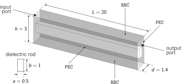
It is possible to analytically obtain the dispersion curve of the NRD guide from simulation results. The parallel metal plates were presented as perfect electrical conductor (PEC) boundaries and radiation boundaries (RBC) were assigned to the upper and lower layers of the model. After simulation, the phase shiftϕ|s21 of the wave at the output port compared to the incident wave at the input port was studied (Figure D.2.
The propagation constantekz can be calculated by. whereLis is the length of the guiding structure and φth phase shifts the field experiences along the length of the waveguide. The propagation constant kz is the spatial equivalent of the frequency representing the number of nodes of the field per unit length.
TENNA
Räisänen, “High Permittivity Dielectric Rod Waveguide Antenna for 110–150 GHz”, në Proceedings of The European Conference on Antennas and Propagation, 2006. Pathak, “Integration of NRD Guide and Slot Line for Millimetre Wave Indoorings indoorings, Waveless indoorings” Propagation in Communication, Microwave Systems and Navigation, 2007, pp. Ma, “Discontinuity of NRD-Guide and its Application in Milimeter Wave Circuits”, International Journal of Infrared and Milimeter Waves, vëll.
Zhang, “Analysis of the characteristics of NRD waveguides loaded with periodic metal strips using the method of lines for millimeter wave filter and antenna applications,” International Journal of Infrared and Millimeter Waves , vol. MARCATILI's method embedded between parallel metal plates (refer to Figure 2.9c) with width a = 2a� and distance from the metal plates d = 2d�. 51 2.40 Measured transmission coefficients11dB of the experimental transition 52 3.1 Spherical coordinate system used for antenna parameter calculation.
DRW end-fire antenna for different values of the plate height in [mm]atf3 = 95 GHz.