This combined fire and evacuation simulation program is called FDS+Evac in this document. The user of FDS+Evac should read each chapter of this manual carefully before starting to use the program.
Getting Started
Features of Limited Functionality
Usually, the user must fine-tune the obstacles in the evacuation masks to correctly represent the evacuation scenario. The evacuation part of the FDS+Evac is stochastic, that is, it uses random numbers to generate the initial positions and properties of the agents.
Most recent changes
If set to true, the agents will stop at the door line if the door/exit is closed. If set to true, the door/exit is included in the door selection algorithm even if it is closed.
Intended Use of FDS+Evac
This chapter provides a brief description of the evacuation module in the Fire Dynamics Simulator (FDS). The companion program Smokeview, written in the C/OpenGL programming language, is used for graphical presentation of the simulation results.
Type of the Model
Model Developers
Relevant Publications
Input Data Required to Run the Model
The same applies the other way around, i.e. by setting the keyword EVACUATION_DRILL=.TRUE.on the MISC name list, one can easily make test runs to see if the construction of the evacuation calculation part has been done correctly. A full description of the input parameters required by the FDS evacuation module can be found in the user manual section of this document.
Model Results
The input file of FDS+Evac is such that with only a minor adjustment a normal FDS calculation can be performed without evacuation calculation.
Uses and Limitations
Applications: There is no feasible model for elevators in the current version of the FDS+Evac. The model therefore uses continuous time and space to track the trajectories of the agents.
Agent Movement Model
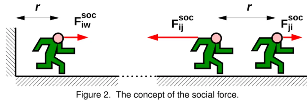
All the force terms in Eq. 2) are relatively short and they need a line-of-sight connection. The vector Rsoci points from the center of agent i to the fictitious contact point of the social force, see fig.
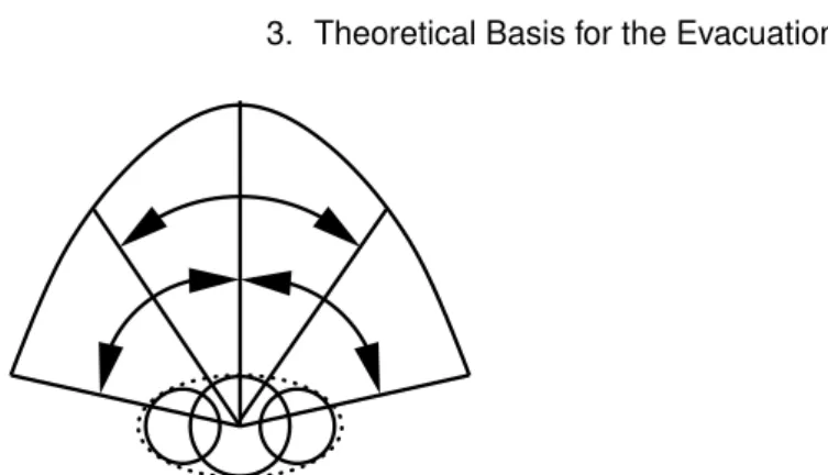
Counterflow Collision Avoidance Model
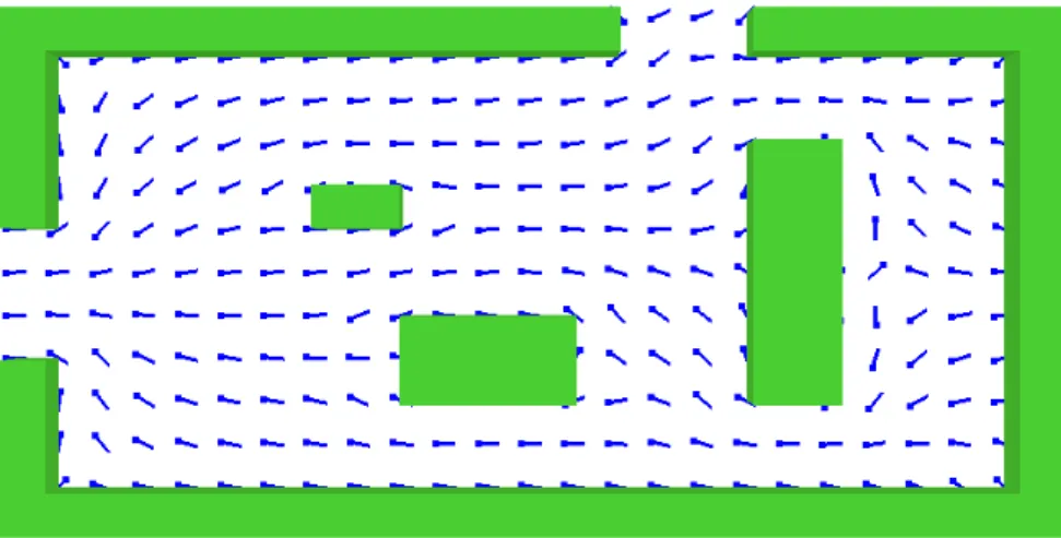
An example of 2-dimensional flow fields used to direct agents toward an exit port. The first parameter is used to provide a negative weight that depends on the agent's velocity and the distance to the wall measured along the direction of the sector, uθi.
Fire and Human Interaction
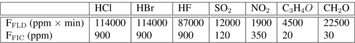
To include the effect of an irritant gas not listed in the table, the user must specify FFLD in ppm×min using theFLD_LETHAL_DOSE property of the corresponding SPEC line. Note that the effect of CO2 is only due to the hyperventilation, i.e. it is assumed that the concentration of CO2 is so low that it does not have direct narcotic effects.
Exit Selection
A follower agent looks at its nearest neighbors and checks whether the exit that the neighboring agents are going to is better than the follower agent's current exit choice, i.e., the follower agent treats its neighbors' intended exit doors as known doors. If there are known exits available to a shepherding agent on a given floor, it behaves as a conservative agent, i.e. the known route behavior takes precedence over the shepherding behavior.
Numerical Method and Other Details
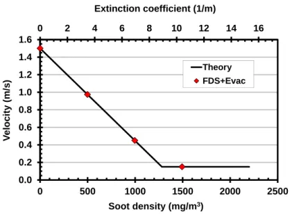
The walking time to the exit door is simply calculated by dividing the distance to the door by the person's unimpeded walking speed. The FDS+Evac verification test archive is on the FDS+Evac website1.
Component Testing
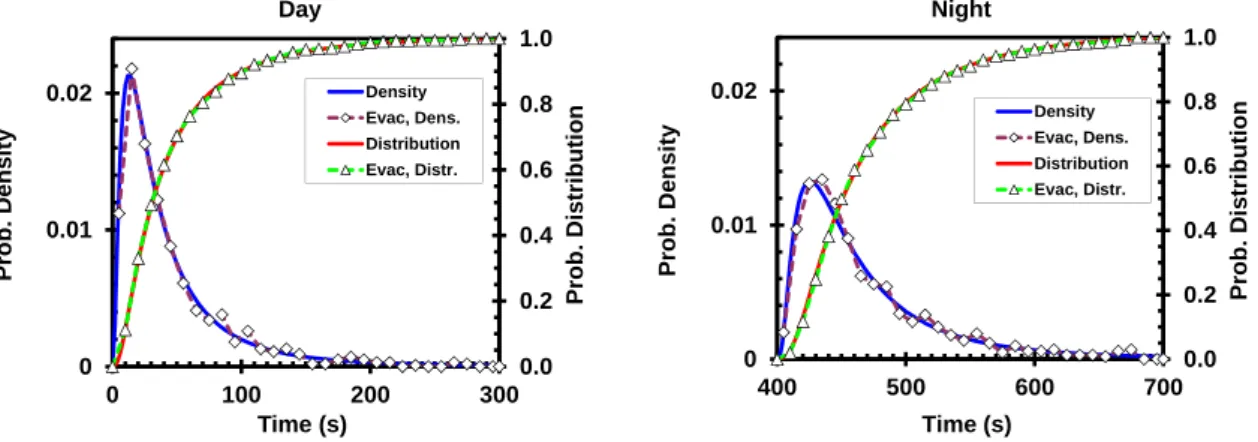
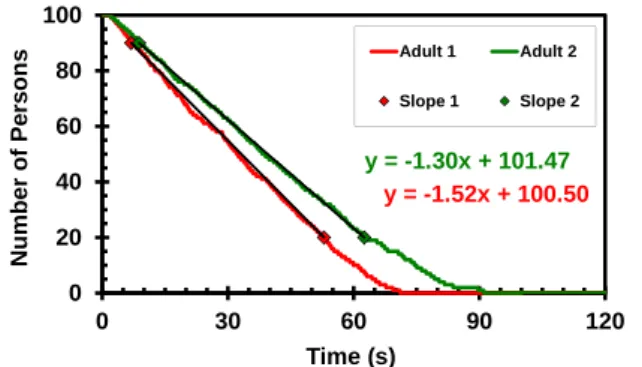
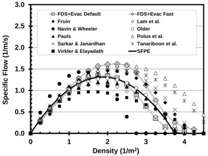
This case has 1000 agents, so the statistical significance of the test for the distribution is much better. The speed of the agents in FDS+Evac simulations was calculated using the time needed to travel the last 5 m in the corridor.
Functional Verification
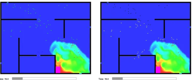
Soot was introduced into the calculations as an initial mass fraction, and the default initial FDS random fluctuations were set to zero and no flow was introduced in the corridor, so that the same constant initial conditions prevailed during the simulation.
Qualitative Verification
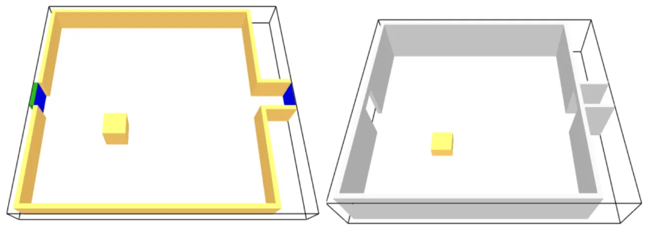
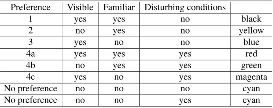
On the left, the agents are colored according to their target exit doors (blue: lower right exit; green: upper left exit) and on the right, the colors of the agents mark the preferred categories of the exit door selection algorithm (black: known) On the right, the agents are colored according to their target exit doors and on the right the colors of the agents mark the preferred categories of the exit door selection algorithm.
Numerical Tests
The input files for the exit selection tests are on the FDS+Evac website. The interested reader can reproduce the simulations and use Smokeview to see if the port selection algorithm works as intended. This section focuses on the effects of different input parameters on FDS+Evac results.
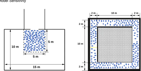
Numerical Mesh Sensitivity
FDS Technical Guide [4, 5, 6] for the effect of the mesh resolution on the FDS fire calculation. There are many more important factors that affect the calculation of the fire-agent interaction than the spatial resolution of the evacuation and fire mesh, eg, the production of CO and other toxic gases depends largely on the user's input.
Human Parameter Sensitivity
This effect is not so pronounced in the case of the corridor, because there is no free space in front of the agents. The social force anisotropy parameter, λi, controls how eager agents are to push those in front of them.
Sensitivity of the Counterflow Algorithm
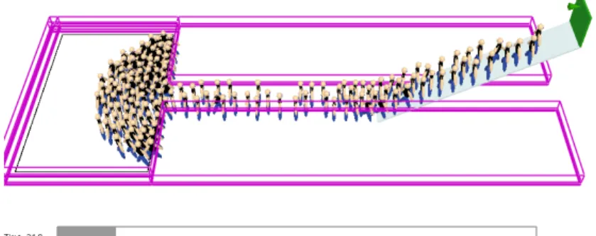
Door widths 1.0 m and 2.0 m were used for doors and corridor widths were 2.0 m and 4.0 m for corridors in the IMO test case 8 geometry. The main idea of the model is to enable counterflow with a reasonably high agent density through short-range collision avoidance.
Summary
The default predefined person types use a value of 0.3 for the social force anisotropy parameter, λi. Note that in the earlier versions of the program the default value of this parameter was 0.5.
Comparisons with Test Data
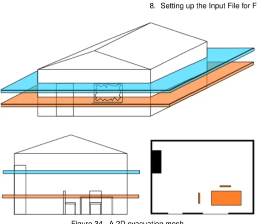
A snapshot of an FDS+Evac simulation shows the geometry of the FDS+Evac model for the second floor of the public library. Comparison of FDS+Evac simulation results and observations at the north and west doors of the public library.
Comparisons with Other Evacuation Models
The results of FDS+Evac simulations are compared with the results of Simulex simulations in Fig. An FDS+Evac simulation is performed in the same way as an FDS fire simulation. Therefore, read the FDS user manual [3], where you can find information on how to run the fire simulation and view the results using Smokeview [14].
Updating an Existing FDS Input File to a FDS+Evac Input File
If you are using the parallel version of FDS, please note that evacuation nets must be defined after all fire nets in the input file. By setting EVACUATION_MC_MODE=.TRUE. only the evacuation calculation is performed and the file CHID_evac.effis is read if it exists.
Getting Help, Error Statements, Bug Reports
If not, it is recalculated. default), then the CHID_evac.fed file is also attempted to be read. By "smart" choice of the z-coordinates of the obstacles (and holes) it is possible to make these objects appear in the visibility and move - ment ("main evacuation eyes") of the eye or in one or the other.
The TIME Namelist Group
The evacuation masks exchange information at each iteration of the main evacuation time step loop, ie. at least every EVAC_DT_STEADY_STATE second. EVAC_DT_FLOWFIELD is the time step for the calculation of the evacuation flow fields.
The SURF Namelist Group
The MISC Namelist Group
EVAC_TIME_ITERATIONS × EVAC_DT_FLOWFIELD defines the duration of the field calculation of the evacuation flow per exit or door.
The OBST Namelist Group
The HOLE Namelist Group
The PERS Namelist Group
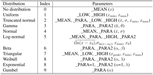
DET_EVAC_DIST Index of detection time distribution type, see Table 5 and Sec. PRE_EVAC_DIST Response time distribution type index, see Table 5 and Section 9.1.
The EVAC Namelist Group
DET_MEAN,DET_PARA,DET_PARA2,DET_LOW,DET_HIGH The parameters for the detection time distribution, see Table 5. PRE_EVAC_DIST The type index for the reaction time distribution, see Table 5 and Sec.
The EVHO Namelist Group
PRE_MEAN,PRE_PARA,PRE_PARA2,PRE_LOW,PRE_HIGH The parameters of the response time distribution, see Table 5. AVATAR_RGB Three integers (0–255) specify a color of the means seen in Smoke-view ifCOLOR_METHOD=0.
The EXIT Namelist Group
PERS_ID This gap only applies to this person type, i.e. it only has an effect on the EVACnamelists where PERS_ID matches. SHOW A logic switch used to control whether the output is displayed in Smokeview or not.
The ENTR Namelist Group
AVATAR_RGB Three integers (0–255) specifying a color of the agents seen in Smoke-view if COLOR_METHOD=0. SHOW A logical switch used to control whether or not the entry is shown in Smokeview.
The DOOR Namelist Group
RGB Three integers (0-255) specifying a color of the agents seen in Smokeview if COLOR_METHOD=4 is specified on (any)PERSnamelist. SHOW A logic switch used to control whether the door is displayed in Smokeview or not.
The CORR Namelist Group
By default, ports are always categorized as usable in the output selection algorithm. The movement time of agents within the stairs is calculated as EFF_LENGTH/(FAC_SPEED×v0i) and no correlation between density and speed is used in this calculation.
The EVSS Namelist Group
ELEVATION The height of the "-IOR" edge of the slope measured from the level of the evacuation plan defined by z e XB. HEIGHT0 The height of the "IOR" edge of the slope measured from the level of the evacuation plane defined by z i XB.
The STRS Namelist Group
The positions of the first two landings are sufficient for the pass, the rest are duplicated from these. The reference time for the evacuation calculation is the start time of the FDS simulation, which is zero by default.
Additional FDS+Evac Input Files
This file is attempted to be read in if there are no firemasks specified in the input file. Note that the FED file is always (re)calculated and saved to hard disk when both fire and main evacuation masks are present in the input file.
FDS+Evac: Output Files
Because FDS+Evac is stochastic, one should do a few dozen evacuation simulations per fire calculation and then this file will speed up the calculation a lot ie. the fire calculation only needs to be performed once. The color scheme of the agents can be changed using the "Show/Hide" menu and the "People" sub-menu, if the selected COLOR_METHOD in the PERSName list allows it.
Restarting a fire+evacuation calculation
The evacuation module of the fire dynamics simulator has been in development for several years. 20] Werner, T., and Helbing, D., “A Social Force Pedestrian Model Applied to Real Scenarios”, Pedestrian and Evacuation Dynamics – Proceedings of the Second International Conference, University of Greenwich, London, 2003, p.