Furthermore, the existing formulas -in many cases- give buckling length factors that are excessively conservative or even underestimated results. In general, obtaining buckling length is straightforward in the cases of fully rigid or hinged joints. This makes the calculation of buckling challenging because the stiffness of the connection must be determined.
Recently, research has been done to develop new formulas for calculating bending length factors. For practical help in running the research, I would also like to thank Teemu Tiainen and Timo Jokinen from Tampere University of Technology. The ratio of the width or diameter of the bearing to that of the chord.
The ratio of the outer width or diameter of the chord to twice its wall thickness.
Introduction
Phenomenon of buckling
The axial load that must act on the element - to make it bend - is called the buckling load. The effective length or bending length describes the ability of a member to resist a load before it begins to bend. It can be defined as the distance between the intersections of the midpoints of the chords and the extensions of the midline of the brace.
1 is the ratio between the width or diameter of the bracing element and the chord, introduced in Ch. 2 is the ratio of the outer width or diameter of the cord to twice its wall thickness, introduced in Ch. For elements with hinged or fully rigid ends, the buckling length factor and thus the buckling length and buckling load are relatively easy to calculate with formulas such as Euler's formula.
There are several sources available with buckling length factors or formulas to calculate the factors in defined final conditions.
Buckling behavior in lattice girders
It does not depend on side supports unless the supports (purlins) are attached to the chord in a rotational manner. Out-of-plane buckling of stirrups is determined by the rotational stiffness of the chord and the potential lateral support provided to the chord.
Investigation of buckling
Literature review
Factors influencing buckling length
If the bottom and top chords are not identical, Boel (2010) recommends calculating the bending length, based on the torsional stiffness, at both ends of the brace and using the higher value obtained. However, the exact definition of the length of the bracket system is not given in Eurocode. For laterally unsupported compression chords, the bending length factor depends on the chord loading, the torsional stiffness of the beam, the bending stiffness of the pins, and the pin joints in the beam.
The support conditions at the bridge ends do not significantly affect the bending capacity. The analysis slightly underestimated the experimental buckling load, which was performed with a fully rigid strut that allowed only vertical movement of the beam at that location. For a laterally unsupported compression chord, Galambos (1998) provided several methods and formulas for calculating the out-of-plane deflection length. 47) described three methods given by Galambos (1998) for achieving a specified bending load on a tendon.
In the book it is summarized that the strength and the bending stiffness of unstiffened joint decreases as the chord slenderness ratio (b0 / t0) increases and decreases. 1977) found that the type of weld has little effect on any aspect of the joint behavior.

Comparing FE results of Fekete to the Eurocode and CIDECT
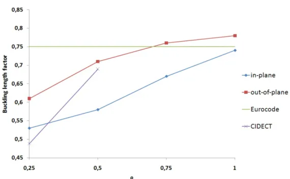
Boel points out that Fekete found that the number of lateral supports only had a significant influence on the out-of-plane buckling of the chordal member. Boel compared the buckling length factors of the chords obtained by Fekete with those given by Eurocode (see beginning of chapter 2). For buckling in and out of the braces, the Eurocode gives a buckling length factor of 0.75 multiplied by the system length between the connections.
Buckling length factor comparison of the results of Fekete, Eurocode and CIDECT for RHS brackets with RHS chord is presented in Figure 2.6. Buckling length factor comparison of the results of Fekete, Eurocode and CIDECT for CHS brackets with RHS chord is presented in Figure 2.7. Buckling length factor comparison of the results of Fekete, Eurocode and CIDECT for CHS brackets with CHS chord is presented in Figure 2.8.
It is concluded that CIDECT almost only gives unsafe results for the buckling length factors in and outside the plane of the struts.

Numerical investigation of Boel
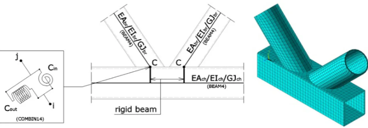
Defining connection stiffness
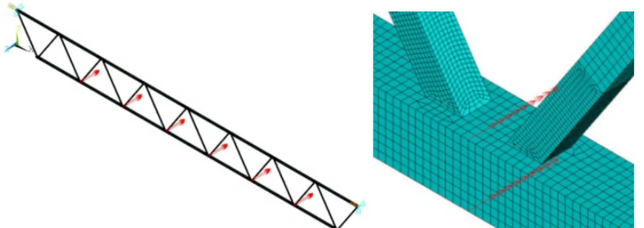
This location gives limits to the system length of the strut members and the chord members (Figure 3.3). To compare out-of-plane stability of the beam element and the shell element model, Boel performed ten reference analyzes of eigenvalues and buckling shapes23. Boel studied the in-plane stability of the connection combinations presented in Table 3.11 with a beam-element model and a shell-element model.
The results showed that the only acceptable agreement was achieved with the average out-of-plane stiffness of all the LCs. In out-of-plane buckling of the struts, large differences occurred by chance, but no consistency was found. For larger values (>0.6) of (in both in-plane and out-of-plane buckling of the chords) the buckling length factor of the chord decreases linearly.
For in-plane and out-of-plane chord bending, an increase in the chord wall thickness causes only a slight increase in the chord bending length factor.

Buckling of braces
The aim of Boel (2010) was to develop better formulas for approximating bending length factors, for cases where existing codes and guidelines do not provide it. In previous chapters, it has been described how Boel has shown the unreliability of Eurocode, the old Dutch code and CIDECT. For all out-of-plane bending of bearing members, Boel stated that the bending length factor appears to increase exponentially.
The Eurocode gives a safe approximation for the chord buckling length factor (0.9), but can be reduced for larger values of (> 0.6). For all out-of-plane chord buckling formulas, Boel has adapted the previously given in-plane buckling formulas. Comparison of chord buckling length factors according to Eurocode and Boel's FE analyzes are shown in Figure 4.2.
Additionally, the dimensional scale (as well as remaining unchanged) must be considered, as it has a large effect on the in-plane and out-of-plane torsional stiffness and thus on the bending length factors (see chapter 3.3.5.) .

Research methods
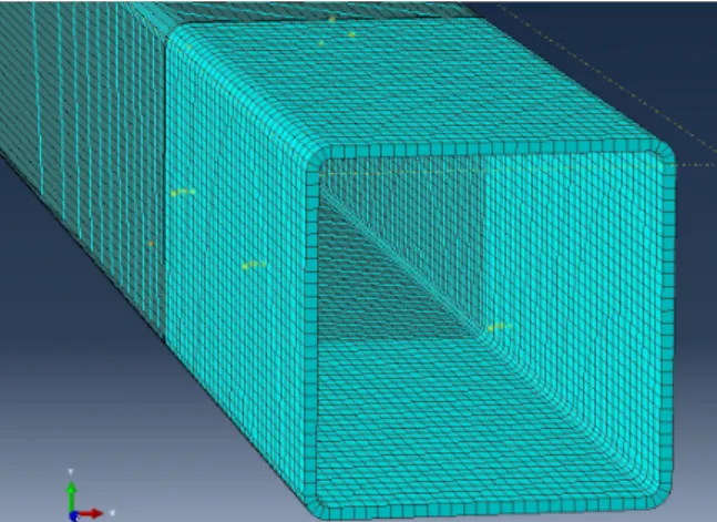
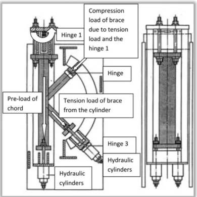
The dimensional and material properties of two of the experimental K-connection tests are adopted in a preliminary FE model55 in Abaqus. Deflections are obtained from FE analysis and they contrast with the numerical results of the experimental study. For demonstration, one of the tested connections is presented with a picture of the deformed connection tested in LUT (Figure 5.3) and the corresponding deformation in Abaqus (Figure 5.4).
One of the validated models was further processed and used for verification with two selected K-joints of the connections studied by Boel (2010). The dimensional, load-bearing and restrictive properties of Boel's joints have been adapted to Abaqus models. Maximum elastic moments (which are undoubtedly elastic) and the corresponding rotations are obtained and in-plane rotational stiffnesses of both joints are derived.
Results of the analyzes are compared with the results obtained with Boel's formulas (2010) and an attempt is made to increase the applicability of Boel's buckling length formulas.
Results
Validation of the Abaqus model
In other words, the width of a stirrup (bi) with fillet welding must be narrower than the flat width (b0 2*r0)57 of the chord in the transverse direction (x direction) of the chord. Load case LCin1 (the case with a moment on the end of the brace on the right, see Figure 3.5) was chosen according to Boel for the calculation of in-plane rotational stiffness. When analyzed without welds, the achieved in-plane rotational capacities were 31-41% less than for the joints with welds.
First, the end of the linear behavior is captured in Figure 6.31, at the point where. Followed by the deformed form of the last numerical calculation (before the joint fails numerically), as shown in Figure 6.32. In this case (with stiffener wall thickness of 3 mm and weld size of 5 mm), it can be seen that the rotational stiffness of the joint with welds is about twice the stiffness of the joint without welds.
Finally, the deformed shape of the last numerical calculation (before the coupling fails numerically) is shown in Figure 6.40. The design of the welds appeared to have a significant influence on the in-plane torsional stiffness of the joints. In four of the seven cases, the in-plane torsional stiffness of a welded joint was about twice as stiff as that of a weldless joint.
The obtained in-plane torsional stiffness decreased significantly when the minimum joint brace was loaded and the maximum bracket supported only the joint (unloaded). Boel (2010) has also developed a new formula for calculating the bending length factors of joint chords K. With Boel's formula (6.17) the bending length factor decreases as the joint stiffness decreases.
It is of interest to see how the bending length factor of the brace changes if the chords are of different cross-sections. As shown in Figure 6.43, there are different flexibility factors at the ends of the brace, Ca and Cb. The stiffness of the joint (represented by Cb) with SHS120x5 chord and SHS110x4 braces is assumed to be greater than that of joint number 3 (SHS120x5 chord and SHS100x4 brace), so it is safe to use this underestimated stiffness.
On the basis of exemplary cases, it can be confirmed that the modeling of welds mainly affects the in-plane rotational stiffness. Doubling the size of the joint sections appeared to increase the in-plane rotational stiffness of the joint almost tenfold. Thus, we can confirm the applicability of the formulas for an even wider range of compound combinations.