A high scientific quality is required from the research projects and their results are shared with the organizations included in the Steering Group. The following is a brief summary of the results of individual projects (Chapter 2) and general financial (Chapter 3) and administrative issues (Chapter 4).

Organisation and human factors research area
Safety management and organizational learning (MANOR)
The main objective of the research project is to examine the factors that promote and hinder organizational learning and the development of a safety culture in the nuclear power industry. A report on the history and present of Nordic nuclear safety culture was written and published in the NKS series.
Expert Work in Safety Critical Environment (SafeExpertNet)
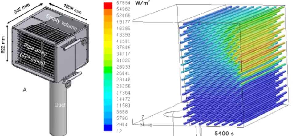
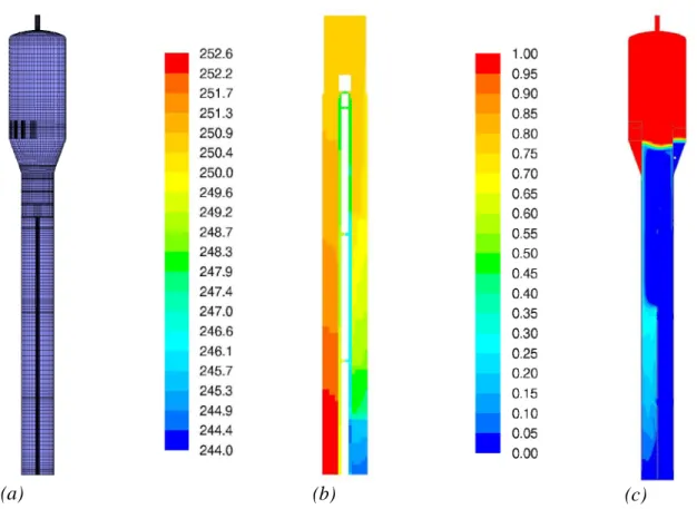
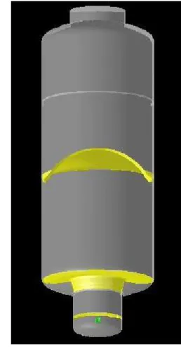
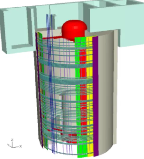
In subtask 1.1, the results of the survey for newly hired individuals were analyzed (n=32, 71%) and reported for the target organization. In figure 2.4.3.2(b) the outer wall temperature of the vertical U-tubes in the primary circuit is shown.
Automation and control room research area
Model-based safety evaluation of automation systems (MODSAFE)
The results of the case study indicate that model checking can be used to verify correct operation and find errors in embedded control software. The case provided valuable insights into how systems combining analog and digital technology can be modeled and what the real limits of the NuSMV model checking tool are.
Certification facilities for software (CERFAS)
Within the COMESTA project, Finland participates in CSARP (Co-operative Severe Accident Research Program). The first periodic report on the work in the EU/NURISP project has been written.

Fuel and reactor physics
Development and Validation of Fuel Performance Codes (POKEVA)
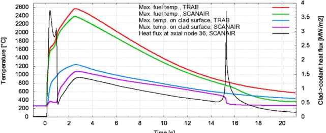
The result of the task was summarized at the international OECD-IRSN RIA seminar in September 2009. The basic purpose of the project is to continue the development of reactor dynamics computer codes (TRAB-3D and HEXTRAN) at VTT, especially in the field of thermal hydraulics.
Total reactor physics analysis system (TOPAS)
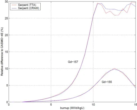
Testing of combustion calculation methods implemented in Serpent (TTA transmutation trajectory analysis and Chebyshev CRAM rational approximation method). As a first step in the development of Monte Carlo combustion calculation methods combined with uncertainty analysis, the Chebyshev rational approximation method was studied and the results of the method development were published in Nuclear Science and Engineering.

Thermal hydraulics research area
Numerical modeling of condensation pool (NUMPOOL)
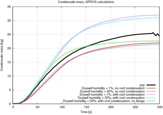
Improvements have been made to the wall condensation model, which improve the stability of the model and enable the use of longer time steps. Some improvements were made to the direct contact condensation model, but more time than initially planned was spent modeling wall condensation in the non-isolated PPOOLEX device.
Improved Thermal Hydraulic Analysis of Nuclear Reactor and Containment (THARE)34
CFD model of the PANDA ships and vertical gas injection line in the left vessel. Strong boiling occurs at the hot side of the riser, where the void fraction is large.

Improvement of PACTEL Facility Simulation Environment (PACSIM)
Calculation of PACTEL experiments SIR-21, SIR-23 and SBL-30 with the TRACE code Calculation of PWR PACTEL pressure and heat loss experiments with TRACE code. Modeling of the PWR PACTEL vertical steam generator with the TRACE code Master thesis by Antti Rantakaulio.

Condensation experiments with PPOOLEX facility (CONDEX)
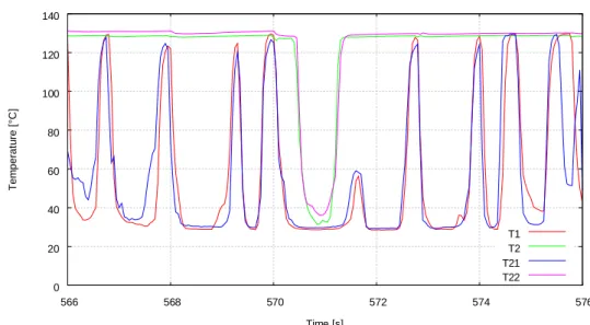
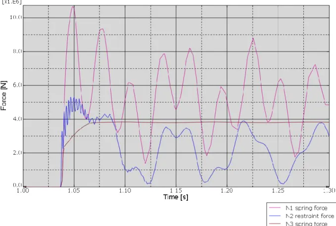
In the two-pipe cabinet, more than twice as high pressure pulses were measured in the blowdown pipe (Figure 2.4.5.3). The pressure loads in the blowdown pipe and in the condensation bath were recorded using various pressure sensors.
Passive safety system simulation (PASSIMU)
A fairly large retrieval of publications on validation activities regarding the passive system designs has been carried out. In some cases, indications of publicly available data on validation activities were lacking, although the nuclear power plant concept and the passive safety system have been designed in considerable detail.

Severe accidents research area
Release of Radioactive Materials from a Degrading Core (RADECO)
The aim of the project is to investigate the behavior of iodine under serious accident conditions. The purpose of the study at VTT is to determine iodine compounds released due to reactions on the surface of primary circuit tubes.

Core Melt Stabilization (COMESTA2009)
These extensive calculations would provisionally complete the analysis of the STYX experimental program. Schematic of the COLOCE vessel with a conical testbed (left, top), a side view of the testbed (left, bottom) and a snapshot of the flame front propagation in a FLUENT simulation of the THAI HD-2R test (right).
Structural safety of reactor circuit research area
Risk informed inspections of piping (PURISTA)
Another task of the third subproject was to participate in an NKS project to investigate the degree of detail required for the assumptions of probability of defect detection in RI-ISI applications. The results of the study show that the use of a simplified POD curve can be justified in RI-ISI applications.

Fatigue endurance of critical equipment (FATE)
Based on the above, we considered that a valid solution for direct deformation control for simulations of transient phenomena in hot water should be developed. This is a bellows unit designed in 2009 to provide the necessary capacity for an 8 mm sample and non-contact strain measurement on the central axis of the specimen under the support frame. The frame and loading system work well, but fitting the strain gauge to the sample and transferring the calibrations to autoclave conditions requires further work.

Water chemistry and oxidation in the primary circuit (WATCHEM)
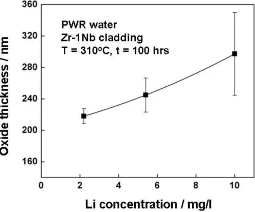
Experimental measurements with Inconel 690 material will be performed in these two water chemistries using the CDE technique at 292oC and the Mott-Schottky technique using passivated samples at room temperature. Experimental research into the optimal length of the passivation period and into the possible positive effect of boric acid addition. Experimental measurements with Inconel 690 material will be performed in water containing 1 ppm Li and.
A scientific article was published together with UCTM, Bulgaria covering all the CDE technique development work related to the oxidation of coating alloys. The main results from the collaboration with BARC, India and UCTM, Bulgaria for the development of in situ methods for optimizing the HFT water chemistry of a PWR plant were communicated in the form of two scientific journal articles. The IAEA Fuel and Water Chemistry 2009 (final) meeting was organized by VTT in Turku, Finland.
Monitoring of the structural integrity of reactor circuit (RAKEMON)
The reliability and usefulness of this method in the examination of real components of the NPP was studied in the literature review. A close collaboration with involved scientists in Japan and elsewhere has begun and will continue in 2010. The inspection data of the eddy current steam generators also contains additional information such as failure signs.
Recently, eddy current data have been applied to demonstrate locations of magnetite deposition on pipes. The improvement of eddy current analysis, for example with regard to the deposition of magnetite on tubes or between tubes and the sizing of faults, was started with a literature review in 2009. Water chemistry plays an important role in nuclear power plants and understanding the variations in the local environmental condition facilitates iron production. deposition in SGs needs to be improved.
Fracture assessment for reactor circuit (FRAS)
For the transient with the lowest flow rate and temperature, steady-state stratification was found only in the nozzle region. Crack growth in welds, including the WRS distributions, was investigated with the fracture mechanics-based analysis tool VTTBESIT, where the stress distributions were taken from the results of the FEM analyses. Engineering tools for fracture analysis were studied and used in combination with a submodeling technique that uses detailed models around the crack area, together with the global model of the structural component. The integrity of the reactor circuit was further studied by analyzing cracked T-connections with a 3D FEM model.
Micromechanical modeling of cleavage rupture would be performed using multi-scale models and the Master Curve method. In the first part of the study, the boundaries of submodeling techniques were defined. The conference paper on Limitations and Application of the Master Curve Method for RPVs (CRP-8 Topic Area 3) was presented in ASME PVP 2009.
Influence of material, environment and strain rate on environmentally assisted cracking of
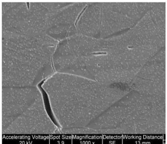
Further observations included macroscopic and local non-uniform distributions of plastic deformation at the surfaces and an influence of local changes in the grain size on the localization of plastic deformation. Impingement of the bands on grain boundaries induced stress blooms in the adjacent grain, Figure 2.6.6.4, which may account for the apparent stress difference observed by EBSD. Whether slip in the form of planes, as in the case of the non-cold-worked material, or actual shear bands, as in the cold-worked material, such slip bands terminating at a grain boundary can lead to stress concentrations at the grain boundary.
TEM image showing shear bands impinging on a grain boundary, causing stress to bloom in an adjacent grain. Differences were also observed in the amount of Si enrichment, from about 2 to 4 wt. % according to the measured composition of the matrix. Recent international research has shown a clear influence of stain level and environment on fracture resistance and tear modulus in the case of nickel-based weld materials.
Renewal of active materials research infrastructure (AKTUS)
Construction safety research area
Service Life Management System of Concrete Structures in Nuclear Power Plants
The purpose of the project is to develop a predictive lifetime management system (SLMS) for concrete structures in nuclear power plants. The methodological basis for the lifetime management system was developed under the EU project LIFECON GIRD-CT. The development and programming of the lifetime management system was to be continued during 2009 by adding new features and ensuring the overall functionality of the Serviceman program.
The cooperation in COST C25 is useful for the implementation of the NPP structures lifetime management system. The object of task 1 was to improve the test apparatus to be suitable for testing stainless steel tubes without a heavy undercarriage. The scope of task 4 in 2008 was to test stainless steel rockets and concrete walls at different speeds.
Structures under soft impact (SUSI)
Probabilistic safety analysis (PSA) research area
CHAllenges in Risk-Informed Safety MAnagement (CHARISMA)
Challenges in risk-informed safety management relate to the use of probabilistic safety assessment (PSA) to support decision-making and to both intrinsic and practical issues in PSA techniques. Preparing the final report of the NKS project and the report of the WGRISK task on PSA criteria. The ultimate goal of the research is to find out what effect different modeling choices have on the computational burden.
Concept documents "Guidance for the application and communication of the probabilistic safety criteria" and final report of the NKS project prepared. The status of risk-based assessments of technical specifications was presented and discussed at a seminar in Stockholm. The results of the second phase (rest of the SGTR scenario) have been evaluated and the final draft of the associated Halden work report has been prepared.
Implementation of Quantitative Fire Risk Assessment in PSA