I would like to thank the current and former team members of the SMIR group for their efficient cooperation and kind assistance. I would also like to dedicate this thesis to my mother for her support, encouragement and love over the years.
Introduction
- Motivation and Problem Statement
- Our Multicore Solutions
- Contributions
- Dissertation Structure
Because it is very small, so it will not significantly affect the cost and complexity of the WSN node. DMRTT and NC together form our multicore architecture, which can greatly improve the reliability and energy efficiency of the WSN node without significant increase in cost and complexity.
General Purpose Dependable System
- Introduction
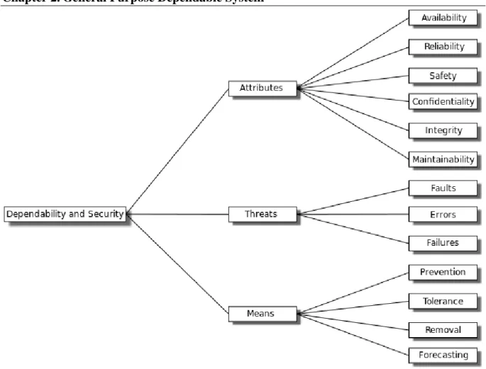
- Dependability Attributes
- Dependability Threats
- Dependability Means
- Dependability Evaluation Techniques
- Dependability Terms
- Dependability model types
- Dependability computation methods
- Fault Tolerance and Redundancy
- Space Redundancy
- Time Redundancy
- MTBF Values Evaluation
- RAS of Computer System
- Summary
The mean time between failures (MTBF) of a system is the average time between failures of the system. The mean time between critical failures (MTBCF) of a system is the average time between critical failures of the system.
Dependability of Wireless Sensor Networks
- Wireless Sensor Networks
- Introduction
- WSN Nodes
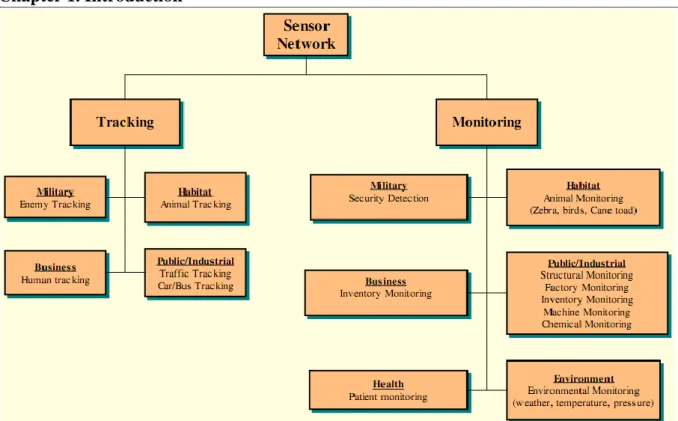
- WSN Applications
- Major Dependable Challenges
- Application Requirement
- Dependability Threats
- Resource Constraint
- Current Dependable Approaches
- Current Approaches
- TMS570 Safety MCU
- Observations of Real World WSN Deployments
- Summary
In PGIS, low-cost WSN nodes can be deployed at each parking lot to detect the condition of the parking lot. Their goals are trying to perform the overall network task, even some WSN nodes are in error status.
Multicore WSN Node Architecture
Introduction
Therefore, we present a novel fault-tolerant and configurable WSN node architecture based on many cores with very low energy consumption. It allows the user to develop software to take advantage of the multitasking architecture features to improve user application reliability.
Multicore WSN Node Architecture
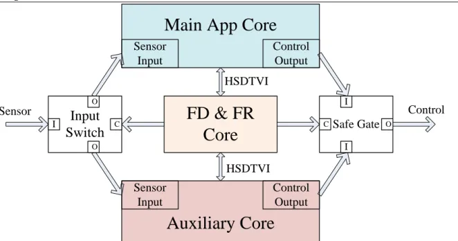
- Generalized Multicore Architecture
- Functional Safety Mechanism
- Fault-tolerant Mechanism
- Resource-aware Mechanism
- Dissymmetrical Multicore Structure
Note that with the current wireless access medium (eg IEEE802.15.4) listening to or receiving a message consumes more energy than sending a message. However, from our point of view, it is essential to examine context-aware, especially resource-aware issues to minimize energy consumption. Compared with multicore system, unicore WSN node system has longer execution time and higher power consumption.
Thus, in the case of a multi-core sensor node, a task can be assigned to a core taking into account its energy consumption (energy efficient allocation as the objective function). However, the concept of symmetric fault-tolerant system in space and time is not suitable for WSN node implementation where energy consumption is one of the most important characteristics.
Different Type of Cores
- IGLOO nano FPGAs
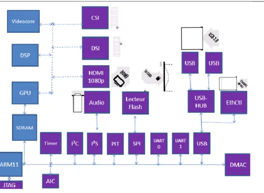
- Raspberry Pi Board
- PandaBoard ES Board
- ARM Cortex TM -M3 Based Microcontroller
- Summary
The Flash*Freeze technology used in IGLOO devices allows entering and exiting an ultra-low power mode that consumes nano power while preserving SRAM and register data. The Low Power Active (static sleep) performance enables extremely low power consumption, while the IGLOO device is fully functional in the system. The NanoRisc is an ultra-low power 4-bit microcontroller that comes in a small 8-pin SO package and operates at up to 0.4 million instructions per second (MIPS).
Based on the ultra-low power characteristic of NanoRisc, it can greatly help to improve the lifetime of WSN node when node is working in sleep and wake mode. The Raspberry Pi board has a powerful SoC that integrates three cores: Low Power ARM1176JZ-F Application Processor, Dual Core VideoCore IV® Multimedia Co-Processor Graphics Processing Unit (GPU) and Image Sensor Pipeline (ISP).
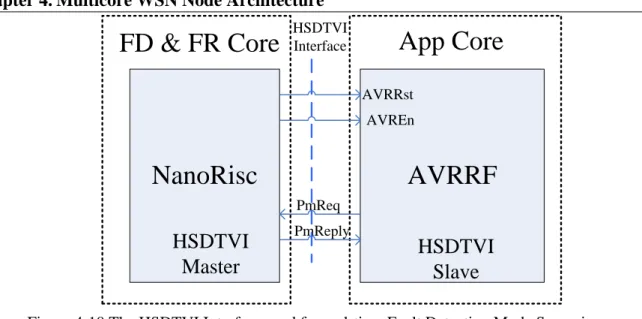
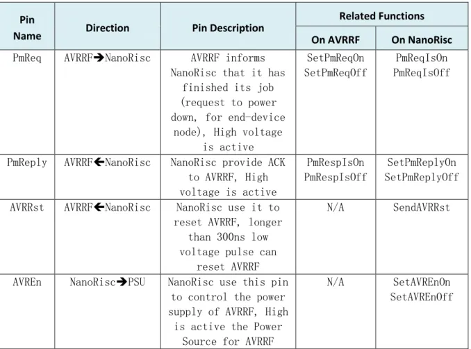
HSDTVI Interface
- Introduction
- HSDTVI Architecture
- Different Scenario of the HSDTVI Implementation
- Summary
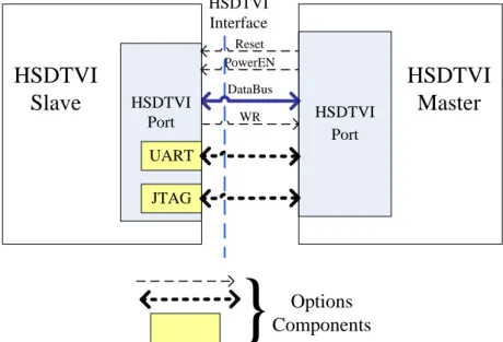
HSDTVI is a communication and control bus between two devices: HSDTVI Slave and HSDTVI Master. If the master HSDTVI has detected an error in the DUT, this pin can be used to reset the slave HSDTVI. iLive can then send these control points to the Raspberry Pi boards via HSDTVI in real time.
The HSDTVI interface provides a new basic method to debug, test and validate the operating state of the microcontroller in real time. The software can act on the fault detection result in the HSDTVI Slave.
Summary
Trace and verify real-world debugging: The HSDTVI Master can be deployed in a real-world environment embedded in the HSDTVI slave. Provide the key technology as Auto-Tester: HSDTVI Master can run appropriate software to check the condition of HSDTVI slave in real time. Therefore, HSDTVI Master can help the developer to check the program automatically, easily for regression testing or long-term monitoring for transient errors.
Force design-before-test way: Ask developers to provide the profile of checkpoints, the edit rules in the profile will be used by the HSDTVI Master. So it can help to implement mutual real-time debugging, testing, error detection and error recovery.
High Reliability Design Process dedicated to Resource
- Introduction
- Traditional Design Process Models
- Waterfall Model
- V Model
- Incremental Model
- Spiral Model
- RAD Model
- Agile Model
- Summary
- High Reliability Design Process Based on Multicore Architecture
- General Overview
- Model-Driven Engineering
- Model of Multicore WSN Architecture
- Early Validation of Requirement
- Design for Multicore Run Time Testability
- Fault Injection
- Summary
The system is developed during the implementation phase, so no early simulation or prototypes of the system are produced. Extreme programming (XP) is currently one of the most well-known agile development life cycle models (K. Beck et al., 2001; Prolinx Services, 2013). Therefore, it is assumed that the top architecture of the node should be multi-core architecture.
That is why we propose to use the defect injection method in HRDP to find out the reason for the defect, to understand more about the defect, and to belatedly help to improve the overall system. And the testbed will also facilitate the development of multi-core software because it can greatly help in discovering unknown bugs.

Implementation of Multicore WSN Node
E² MWSN: High Reliability and High Performance Multicore WSN
- Hardware Architecture
- Key Features
- Performance
The circuit can control the power supply of each core independently, so the E²MWSN can operate in different modes, as shown in Table 6-1. To evaluate the power consumption of the E²MWSN in different operating modes, the total operating current of the E²MWSN is measured as shown in Figure 6-4. Since the E²MWSN multicore mode is more energy efficient, it can achieve a longer lifespan than other modes.
With a pair of AA lithium/iron disulfide (Li/FeS2) 3000 mAh batteries and the sampling period is 3 minutes, the lifetime of the E²MWSN multicore mode is 1270 days. Mean time between failure (MTBF) and mean time between critical failure (MTBCF) were calculated to evaluate the reliability of E²MWSN.
- General Overview
- Hardware Architecture
- End-Device Sleep & Wakeup Work Mode
- Key Features
- Performance
Based on the ultra-low power characteristic of NanoRisc, it can greatly help to improve the lifetime of iLive when iLive is working in sleep and wake mode. In deep sleep mode, the AVR RISC will also be turned off to further reduce the total power consumption of iLive. The TNormalON running mode of iLive is similar to in TInitON, iLive will switch between active mode (stay for TActive) and sleep mode (stay for TSleep).
To evaluate the power consumption of the iLive, the total running current of iLive is measured as shown in Figure 6-9, similar to Figure 6-4. Because iLive does not have redundancy core, the MTBF and MTBCF of iLive are the same value.

SIS: High Reliability Sensor Node in Smart Irrigation System
- General Overview
- Hardware Architecture
- Key Features
- Performance
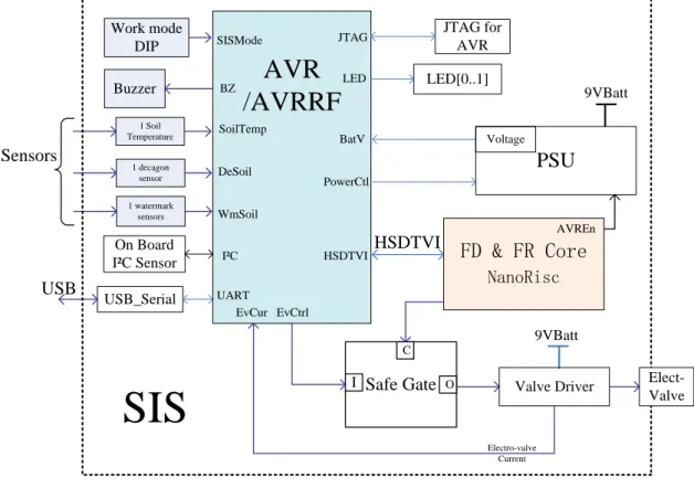
This method can greatly improve the security of SIS and prevent flooding when a fault occurs. To estimate the power consumption of the SIS, the total current of the SIS is measured as shown in Figure 6-13, similar to Figure 6-4. When the soil moisture is at the appropriate level, the SIS will return to the idle state without controlling the solenoid valve after detecting the soil moisture.
Therefore, SIS energy consumption is measured separately for normal and dry soil moisture. Therefore, the MTBCF of the core components in the solenoid valve control SIS is 1.48E+15 hours, 1.69E+11 years, making the SIS particularly safe.
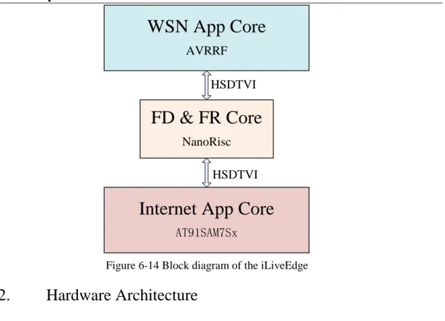
- Hardware Architecture
- Key Features
- Performance
FD & FR Core NanoRisc will run as a monitor for both AVRRF and AT91SAM7Sx to improve the reliability of iLiveEdge. For the local WSN part in iLiveEdge is coordinator, normally this part cannot sleep. In order to provide continuous services, iLiveEdge requires continuous power supply such as mains AC-DC or large rechargeable battery with continuous power generators.
Since the iLiveEdge does not have a redundancy core, the MTBF and MTBCF of the iLiveEdge are the same. From Table 6-13, we can see that the MTBF of the iLiveEdge is 8.08E+06 hours or 923 years, large enough to meet the requirements of most applications.
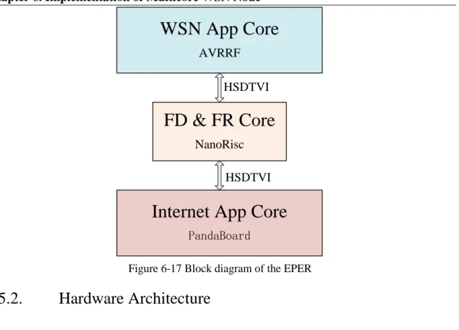
EPER: Highest Performance High Reliability and Multi-Support
- General Overview
- Hardware Architecture
- Key Features
- Performance
As noted in Figure 2-4 and 2.2.1.6, the MTBF/MTBCF is the failure rate (bottom of the bathtub curve) of core components and not the MTBF/MTBCF of the WSN node board. The FD&FR Core NanoRisc will run as a monitor for both the AVRRF and the PandaBoard to improve the reliability of the EPER. For the same reason, power consumption is not the most important parameter of the EPER.
To provide uninterrupted services, EPER also needs uninterrupted power supply, such as AC-DC in the mains, a large storage battery with renewable energy generators, etc. Since EPER does not have a redundant core, MTBF and MTBCF of EPER are the same.
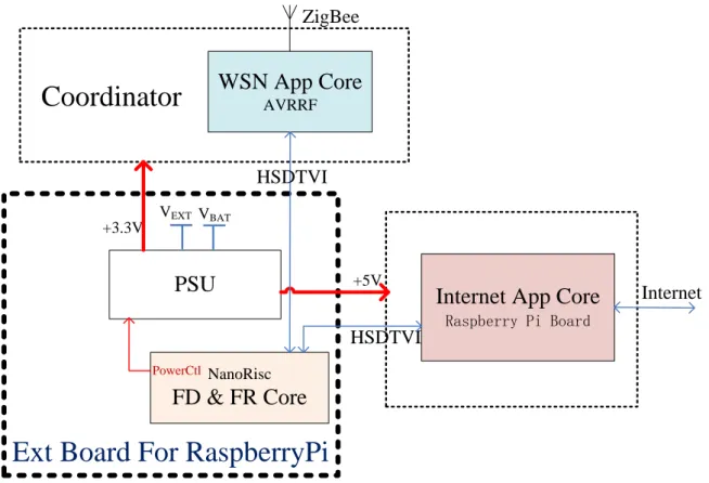
RPiER: Higher Performance High Reliability and Multi-Support
- General Overview
- Hardware Architecture
- Key Features
- Performance
The FD&FR Core NanoRisc will run as a monitor for both the AVRRF and the Raspberry Pi board to improve the reliability of the RPiER. For the same reason, power consumption is not the key parameter for RPiER. In order to provide continuous services, RPiER also requires continuous power supply such as AC-DC on the mains or large rechargeable battery with continuous power generators.
Since the RPiER does not have a redundancy core, the MTBF and MTBCF of the RPiER are the same. From Table 6-15 we can deduce that the MTBF of the RPiER is 3.18E+06 hours or 363 years, large enough to meet the requirements of most applications.
Related Projects
- Precision Agriculture
- Smart Irrigation System
- Smart Environment Explorer Stick
In addition, SEE-stick supports many wireless access media, such as WiFi, 3G, and IEEE 802.15.4 etc. The IEEE 802.15.4 RF part, supported by the AVRRF core, will provide the SEE-stick to access the local ITS 'Intelligent' Transport System", which can greatly help the SEE-stick to provide more accurate signals and reliable mobility SEE-stick will operate in a real, unpredictable, physical environment that makes mistakes inevitable.
We expect that the checking and recovery mechanism on multicore and multi-support wireless can greatly help in building a robust SEE stick. Currently, the SEE stick is still in development stage, but there is a remote monitoring demo available at http://edss.isima.fr/sites/smir/sees.
Summary
From Table 6-18, we can find that the reliability of multicore WSN node is very good, MTBF/MTBCF for nodes can up to 5000 years. Even for complex edge routers, the MTBF/MTBCF of ER is also over 200 years, large enough for most of the applications.
Conclusion and Ongoing Work
Conclusion
Next Generation WSN node
- Next Generation Multicore SoC for WSN node
- Finite State Machine OS: FSMOS
In addition, Off-Chip communication of Multicore SoC should also support common interface like I²C, SPI and UART. To ease implementation and avoid duplication of work, we will develop a native real-time operating system integrated with all the core functionality related to every aspect of the multi-core architecture, such as the core hardware driver, cluster communication standard, resource management, basic inter-communication, power management and remote process communication. FSMOS Direkt supports Multicore Architecture, provides all basic multi-core system service, such as inter-core communication, multi-core power management and remote process communication.
The main source code of FSMOS is C Language and these codes should directly support cross-compiler and can run on different platforms such as AVR, ARM7, ARM11 and PC (WIN and Ubuntu). FSMOS is a cross-platform design so it can run on different platforms such as AVR, ARM7, ARM11, PC (WIN and Ubuntu) etc.

Perspective
All devices at home or in the factory connect to the Internet of Things through these invisible wireless sensor networks. Wireless Sensor Networks: A Survey of the State of the Art and 802.15.4 and ZigBee Standards. Paper presented at the USENIX Annual Technical Conference, Anaheim, CA.
FlexiMAC: A flexible TDMA-based MAC protocol for fault-tolerant and energy-efficient wireless sensor networks. Design and Implementation of a Test Platform for Wireless Sensor Networks Middleware Advances in Wireless Sensor Networks (pp Springer.