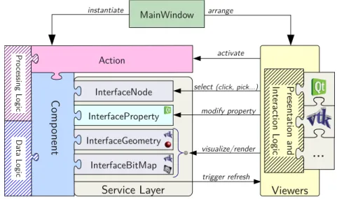
CamiTK core therefore introduces simple light standards for software modules that can be found in the CAMI application. Like CommonTK1, CamiTK defines low-level software components that can be used to build viewers (see Figure 5).

Component
Thanks to the service layer, the PropertyInterface is used in the property viewer to allow the user to interact with some of the encapsulated data of the component, such as viewing the dimensions of a medical image or changing the color of a mesh. A component cannot have a graphical representation, or it can have one of the following two: 3D geometry or a bitmap (a flat image of a certain thickness). Under the hood, 3D geometry is handled by vtkPointSet and bitmaps are handled by vtkImageData.
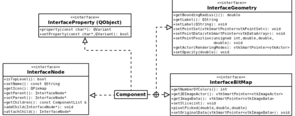
In the considered design pattern, the Componentclass is the adapter and the GeometryandSlice classes are the adapted classes. They provide all the concrete implementation of the 2D/3D visualization service and define a lot of default behavior. One of the main advantages of the Object Adapter pattern is to simplify the construction of the 2D/3D representation.
The CamiTK extension wizard generates the extension class header and code, the component class skeleton as well as the CMake configuration file: integration of a new component into the project, compilation, linking and configuration is therefore fully automated.
Action
Both classes allow for rapid integration of user data based on geometries and images, respectively. It defines the extension name, the supported file suffix for opening and exporting and the dynamic or shared library itself. ImageComponentExtension and MeshComponentExtension speed up the development of user data plugins to provide image-based or mesh-based support in CamiTK. For example, Image-ComponentExtension is the base class for DICOM and JPEG plugins, while Mesh-ComponentExtension is the base class for the VRML and PML plugins.
Application
Use-cases and Tutorials
A new type of interaction with the data or a new way of visualizing the data. Optionally add a new user setting (5 lines of code) to preserve the value between two Action Extension runs.

Comparison and Evaluation of Soft Tissue Modeling
In the rest, such software and libraries where soft tissue models are implemented are called generic. It is very challenging to compare them because models may not have the same structure (eg discrete, continuous, meshless) and may be implemented in different simulation engines. However, comparisons between algorithms are crucial to determine their relevance for a specific medical application, depending on the targeted level of compromise between computational efficiency and computational accuracy.
Validation is the process of determining the level to which a verified computational model accurately represents the reality of interest [12]. In soft tissue simulation, validation is often performed by comparing simulation results with in vitro or in vivo experiments. Therefore, validation studies often rely on a limited amount of testing, which implies only partial validation.
We propose an environment called the MML framework that facilitates communication between different simulation engines and enables comparisons between algorithms built from different modeling techniques.
Environment Overview
Furthermore, numerous implementations of these models have been developed in-house, by communities of scientists (e.g. SOFA [5] or ArtiSynth [8]) or by commercial software developers (e.g. ANSYS, Comsol, Abaqus). The heterogeneity of modeling techniques and the number of existing implementations lead to a wide variety of available algorithms. If these algorithms are to be used for clinical purposes, they must prove that their predictions are correct.
These experiments are quite difficult to perform because boundary conditions are difficult to control, especially during in-vivo experiments. The second main objective is to propose a generic and shareable description of validation experiments to fill the lack of validation references.
Generic Description
MML describes a reproducible simulation by integrating PML and LML description along with the list of data to be monitored, simulation parameters (e.g. integration steps) and stability criteria. The use of a stability criterion to determine when a simulation is considered complete is discussed in section 3.5.2. In section 4, an example of an MMLin description for a simple simulation is given. Having a simulation described by an MMLin document allows the same exact simulation to be reproduced on different simulation engines so that comparisons can be made between them.
MMLout describes monitored data and stability criterion values for each step of the simulation. MMLout can be saved after simulation to be used as a comparison reference for other simulations. In this case, the MML framework benefits from the integration in CamiTK where medical imaging taken from real experiments can be processed (e.g. segmentation, 3D reconstruction) and converted into MML description (see section 4 for ' an example of the workflow from medical images to MML description with CamiTK).
Once saved, MMLout documents can be used for automatic comparison with future simulations of the same problem using the corresponding MMLin document as input.
Simulation Engines
In non-interactive simulators, all calculations are generally done in one big step by the simulation engine and post-processed afterwards. Interactive simulators have the adoMove() method, which causes the simulation engine to calculate one simulation step. This method is replaced by the doAllCalculations() method in non-interactive simulators, which starts the calculations that can be post-processed.
A set of methods (only the getPosition() method is represented in Figure 11) allows to retrieve calculated data for a given step from the simulation engine. To simplify the development of new plugins, we try to keep the interaction with the simulation engines as easy as possible, so that no extra code has to be written in the simulation engine. Therefore, only the getPosition() method needs to be implemented in a plugin to be able to calculate a large amount of metrics, as described in section 3.5.
While in ArtiSynth the user can interact with the simulation at each step using controllers or screens, in the current version of MML the Artisynth plugin is considered a non-interactive simulator because we did not have immediate access to a C++ API.

Metrics
If the models and reference do not have the same structure (eg, the reference has more nodes than the model), node set comparisons can be used. If the model and reference are made of a mesh, volume and area comparisons are possible. All the metrics given here as examples only need the positions of the model nodes at a given time and can then be calculated if the getPosition method is invoked.
Indeed, even if calculations are fast (i.e. if the FPS is high), a model cannot be used in an interactive simulation if it requires a large number of iterations to reach equilibrium. The stability criterion is defined by a Boolean expression using tests on basic data extracted from simulation (eg positions) or externally calculated from this data (eg velocities or kinetic energy). This Boolean expression can be a complex combination of tests (eg, a decreasing global kinetic energy and all nodal kinetic energy below a given threshold value).
The stability criterion is defined in the MMLin document so that the same criterion can be used for all simulations based on the same experiment.
Implementation and CamiTK Integration
This library can be used independently of CamiTK to build stand-alone applications, such as building an optimization application that can use computed metrics to optimize arbitrary model parameters (including mesh or rheology), or a sensitivity analysis application that can automatically explore spaces parameters. A special action has been added to interact with the simulation engines and display the calculated metrics as color-coded or vectors in the interactive viewer (see Figure 12). Its simulation tab can be used to interact with the simulation parameters (integration step, PML and LML documents,..).
The "emulator" tab is used to display the specific simulation engine plugin widget (if available). This section presents an example of a CAMI application that can be performed with CamiTK from opening and displaying the image volume to comparing the deformation model2. Because the tissue has moved or deformed, the structures of the brain during surgery are not where they can be seen on preoperative images.
A soft tissue simulation can therefore be used to estimate the deformations caused by the brain shift.

Image Analysis and Mesh Generation
During neurosurgery, when the surgeon opens the patient's skull, the brain deforms due to physical changes, including the loss of cerebrospinal fluid, surgical instrument interactions and resections, as well as physiological changes due to, for example, inflammation, drugs and anesthesia. This is especially true when one considers the targeted tissues or zones: for example, a tumor area may be displaced or the cortex may be compressed compared to pre-operative images. 14 Use the Lookup Table action to visualize an image component and choose between various brightnesses and contrasts.
In this tutorial example, it is possible to segment the brain in a simple but effective way with the ITK algorithms available as CamiTK actions. Of course, we can imagine more accurate, robust or efficient ways to segment this tissue thanks to ITK or other algorithms. Integrating such algorithms into the CamiTK framework would require only a few lines of code and requires only one to link the algorithm to vtkImageVolume.

Model Comparisons
15 Simplified visualization of the MML description of the ANSYS reference simulation (MMLin) and its results (MMLout). For the mass-spring model, a spring is placed at each edge of the tetrahedral mesh. This standalone program iteratively calculates the average distance between the ANSYS reference and the simulated positions obtained by SOFA.
The time to reach stability represents the time to reach the stability criterion defined in section 3.5.2. The computation time is the total time that the simulation engine needs to compute all steps of the simulation. The mass-spring model is the fastest (almost ten times higher FPS than FEM) but has the highest distance from reference: the average distance from reference is three times more important than SOFA FEM, and the maximum is close to 5 mm, which would be a critical problem for neurosurgery, if we consider the ANSYS simulation close to reality.
Acknowledgments The authors would like to acknowledge the support of the French Ministry of Research (PhD grant) and of ECCAMI (Excellence Center for Computer Assisted Medical Interventions, www.eccami.com), a community of practice that brings together clinicians, researchers. and manufacturers.