HAL Id: hal-00805465
https://hal.archives-ouvertes.fr/hal-00805465
Submitted on 27 Mar 2013
HAL is a multi-disciplinary open access archive for the deposit and dissemination of sci- entific research documents, whether they are pub- lished or not. The documents may come from
L’archive ouverte pluridisciplinaire HAL, est destinée au dépôt et à la diffusion de documents scientifiques de niveau recherche, publiés ou non, émanant des établissements d’enseignement et de
Human-computer interaction for the generation of image processing applications
Régis Clouard, Arnaud Renouf, Marinette Revenu
To cite this version:
Régis Clouard, Arnaud Renouf, Marinette Revenu. Human-computer interaction for the generation of image processing applications. International Journal of Human-Computer Studies, Elsevier, 2011, 69 (4), pp.201-219. �10.1016/j.ijhcs.2010.12.002�. �hal-00805465�
Human-computer interaction for the generation of image processing applications
R´egis Clouard, Arnaud Renouf, Marinette Revenu
GREYC (ENSICAEN and University of Caen), 6, boulevard Mar´echal Juin, 14050 Caen, FRANCE
Abstract
The development of customized image processing applications is time con- suming and requires high level skills. This paper describes the design of an interactive application generation system oriented towards producing image processing software programs. The description is focused on two models which constitute the core of the human-computer interaction. First, the for- mulation model identifies and organizes information that is assumed neces- sary and sufficient for developing image processing applications. This model is represented as a domain ontology which provides primitives for the formu- lation language. Second, the interaction model defines ways to acquire such information from end-users. The result of the interaction is an application ontology from which a suitable software is generated. This model emphases the gradual emergence of a semantics of the problem through purely symbolic representations. Based on these two models, a prototype system has been implemented to conduct experiments.
Keywords: Human-computer interaction, Knowledge acquisition, Ontology design, Image Processing and Computer Vision
1. Introduction
The development of image processing applications has proven to be a highly complex and time consuming activity. This prevents the penetration of image processing into industry, whereas the demand for concrete appli- cations is growing in all domains: medicine, biotechnology, remote sensing, astronomy, ecology, security, forensics, chemistry, surveillance, quality con- trol, etc. As a result, it is becoming important to develop systems that can help end-users build customized applications. The challenge is to allow end-users to program software at the image feature level rather than at the computer code level.
This paper is meant as a contribution to the development of a system ori- ented towards producing customized software programs for image processing applications. Such a system is first configured “off-line” by image process- ing experts, with resources required to process images in a given application domain, for example segmentation of cytology images. Then, the system is distributed to end-users of the target domain, for example cytotechnologists.
Users interact “on-line” with the system to autonomously produce concrete applications in the target domain. Their role is focused on query formulation.
In absence of consensus on a clear-cut boundary of the image processing field, we supply our own definition so as to delineate the project scope.
Definition 1. Image processing is any form of image-to-image transforma- tions without any interpretation of content, for which input data are iconic images and output data are iconic, intrinsic, or segmented images.
Our definition locates image processing applications as one component of the low level part of more global image analysis or computer vision systems.
Thus, image processing is not an end in itself and it has no decision-making authority. Its role is completely determined by the high-level part which uses its results to perform interpretation, visualization, storage, or transmission of image data. Definition 1 is stated from the point of view of the trans- formation objectives and the input image types. It is narrower than other definitions available in the literature (e.g., [1, 2, 3]), and excludes higher level categories of objectives such as feature extraction, object classification, and object recognition. Only six categories of objectives are considered:
• Restoration objectives refer to recovery of an original image from de- graded observations, knowing the degradation phenomenon.
• Enhancement objectives concern the improvement of the visual quality of images.
• Compression objectives address problems related to the reduction of the amount of data needed to store a digital image.
• Reconstruction objectives intend to infer new spatiotemporal informa- tion such as shape, 3D, and motion.
• Segmentation objectives aim at structuring signal information into more abstract primitives such as regions, contours, and points of interest.
• Detection objectives seek to build positive masks that locate informa- tion of interest.
These six objectives are considered independent. However, Definition 1 makes no assumption about the way they may be achieved. For example, an image segmentation program can be implemented by means of restoration, enhancement, and feature extraction operations.
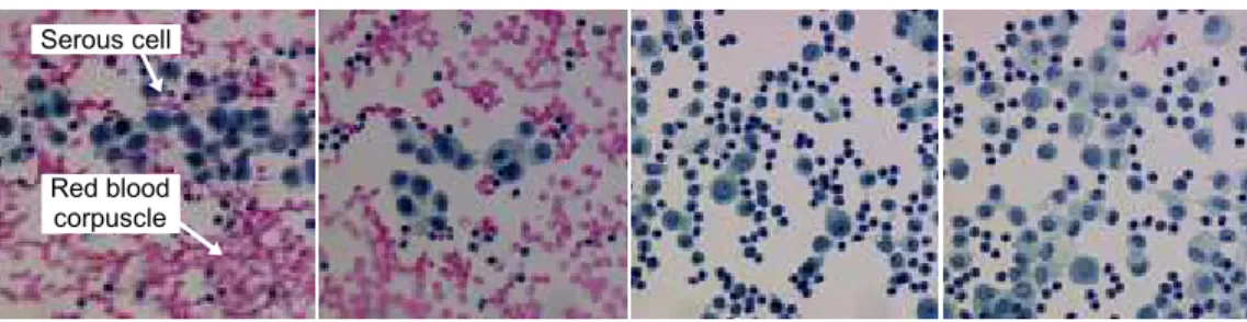
An image processing application is devoted to one of the above mentioned objectives and one class of “similar” images. Consider the following image analysis application that will be used as a running example throughout this paper. It is a biological application in the context of cancer screening de- scribed in [4]. The purpose is to assist cytotechnologists in finding suspect or abnormal cells from the analysis of serous cytology images. Within this im- age analysis application, the specific image processing objective is to segment images into regions corresponding to individual cells. Then, the resulting re- gions will be fed into a classifier which has been trained to identify the various cellular types. The image class (see examples Figure 1) is composed of color images of serous effusions acquired by an optical microscope always under the same resolution and illumination conditions.
Figure 1: Four samples of microscopic images of serous effusions. (Reproduced by courtesy of the Pathological Anatomy and Cytology Department of the Public Hospital Center of Cotentin.)
Within application generation systems, the interface between human and computer plays a preponderant role. This interface is the only means to take into account end-user requirements. Its expressive power determines the scope of the system and its degree of compliance with the user requirements.
In this paper, we argue that the formulation interface must be more than a simple passive control panel that exhibits the elements identified as necessary for carrying out the solutions stored into the system. Indeed, through such control panels, users believe they develop customized applications, but in fact they only choose and parameterize ready-made ones. Actually, the pre- existing solutions are hidden under a predefined list of task names exposed on the interface, and the parameters are hidden under a predefined list of image features to be set. Thus, the query is composed with the same list of features for every problem, only feature values may change.
On the contrary, to cope with unanticipated problems and to develop genuine customized software programs, the solution and the query should be built incrementally by complementarity between the user and the system [5]. The query should be composed with only relevant features, and the program should be constructed by aggregation of solution elements according to the query composition. In this new perspective, the interface provides a formal language that allows for rich formulation of application problems, and organizes the cooperative problem-solving process by dynamically linking user formulation elements to solution elements provided by the system. As a result, the final software program is the best compromise between user intentions and system processing capabilities.
This idea has been in use in interactive image segmentation for a long time [6], and more recently in image retrieval [7, 8]. But it is difficult to implement in the case of interactive construction of image processing applications. The main difficulty stems from the need to design a solution that will suit a whole class of images, and not only a single image. Some recent works have been undertaken with the idea of complementarity between human and computer for the interactive development of image processing applications, such as those of Draper et al. [9], Levner et al. [10], Nouvel et al. [11], or Hudelot et al. [12]. But to reduce complexity, these systems remain limited to sole cases of image segmentation problems where the concept of describable and measurable objects of interest exists in the scene.
Our goal is to propose a general purpose system that covers all the image processing objectives as stated in Definition 1, and that is domain- independent. In its current state, the system is limited to 2D and 3D still images. If users no longer have to be image processing experts, they still need to have image processing skills, since they have to identify what image information is relevant for performing accurate processing.
This paper is focused on the definition of two models that are the pre- requisite for the design of such interactive systems: the formulation model and the human-computer interaction model. The formulation model iden- tifies what kind of information is necessary and sufficient for the system to produce customized software programs. This model provides the basis for the definition of a query language. The interaction model identifies ways to collect this information from users in order to compose queries. However, problems raised by the generation of the software solution as well as those raised by the evaluation of the image processing results are beyond the scope of the paper. The rest of the paper is organized as follows. Section 2 first discusses the problematics of the formulation of image processing objectives and then presents a review of various approaches to address this issue. Our formulation model is detailed in Section 3. The formal representation of
formulation information rests on a domain ontology, which is presented in Section 4. Section 5 details the human-computer interaction model and the means to acquire formulation information from end-users. Then, experiments and discussion of the results are given in Section 6. Finally, conclusions and future directions of research are presented in Section 7.
2. Image processing formulation problematics
The purpose of this section is to explain why it is so complex to provide formulations of image processing applications and to review some approaches from the literature.
2.1. Why image processing application formulation is necessary?
Inferred from Definition 1, we propose the following definition of image processing application, stated from a functional standpoint:
Definition 2. An image processing application is a software specialized in the achievement of a given image transformation goal from input images belonging to a given class.
This definition clearly determines an image processing application by one image transformationgoaland oneimage classdefined as a set of images that share common features. Therefore, one can conclude that the development of image processing applications is not an activity that operates without purpose and knowledge about the objective. The reason is twofold. First, image acquisition is responsible for creating incomplete, degraded, and cor- rupted images that underconstrain the observed scene (e.g., noise, blur, loss of motion or depth) [13]. Second, the image content has no meaning in itself.
An image is inherently ambiguous and does not provide information about its content. Without a goal, an image cannot allow to discriminate between relevant and irrelevant information. For instance, apparently simple informa- tion like object edges is impossible to extract accurately without knowledge about the type of edges observed in the images. Edges are usually modeled as sharp changes in image intensity, but it is also the case of noise, shadows, and texture elements. Accordingly, the problem to be solved is external to the input images and therefore a problem formulation is required.
2.2. What is involved in an image processing application formulation?
Every image processing algorithm is built on a presupposed model of the information contained in the images which conditions its domain of definition.
Consequently, the formulation aims at providing an explicit representation of the model of information to be considered for a given application which
allows the system to select relevant algorithms. As pointed out above, the model of information should be composed of three categories of information absent from the input images:
1. the expression of the goal in order to give the subject matter of the application;
2. the description of the image acquisition process in order to reveal lost, altered, and hidden information about the observed scene;
3. the definition of the application domain concepts in order to assign meaning to the observed scene by designating information to be con- sidered as relevant in the images.
The first category of information is collected during the goal specification, and the last two categories during the image class definition. Therefore, an image class is a set of images which share common features in terms of acqui- sition effects and relevant information. All these information elements must be provided by users. However, the difficulty is to set an appropriate formu- lation level since humans provide a semantic interpretation of the problem whereas computers use a symbolic representation. Hence, formulating means bridging the sensory and semantic gaps that separate the real world, which is the level of the problems, from the symbolic world, which is the level of the processing solution. The sensory gap results from the acquisition. It is the difference between objects in the world and their representation in images [7].
The semantic gap is the difference between the interpretation of a scene that one can make from images and the interpretation made from a denotation of the image contents in terms of symbolic features [7]. Therefore, the role of the human-computer pair is to express a real-world problem as a set of measurable symbolic features.
2.3. Related works on image processing application formulation
Two approaches for image class definition as well as two approaches for goal specification can be identified in the literature.
2.3.1. Image class definition
The two approaches to image class definition distinguish between the iconic description (definition by extension) and the linguistic description (def- inition by intension).
Definition by extension. In this approach, relevant information elements are represented by sample image parts. In order to perform image processing, a list of measurable features should be extracted from these sample image parts. Two types of sample image parts can be considered: blobs and patches.
• A blob surrounds an image area that isolates one visual manifestation of an object of interest (e.g., Figure 2.a) or one acquisition effect. For example, noise features can be calculated from an image area that is supposed to be homogeneous in the scene. Blobs can be drawn manually or obtained from an automatic segmentation [14, 15].
• A patch is a thumbnail that isolates one visual manifestation of one salient part of one object of interest. Thus, an object of interest is identified by a collection of patches together with the spatial relations between one another (e.g., Figure 2.b). Patches are the terms of an iconic vocabulary used to describe the various appearances of an ob- ject of interest. Generally, patches are automatically extracted from sample images around the interest points [16, 17], which are regarded as information-rich locations.
Figure 2: Two different ways to define by extension the commercial vehicle of image (a), from blob (b), from patches (c).
Definition by intension. In this approach, the definition of image classes is done using a linguistic description of the relevant information. The formu- lation language is generally built over a domain ontology which provides the concepts for describing the image classes and the role of these concepts. This approach is widely used in content-based image and video retrieval, most of them inspired by the MPG-7 standard [18, 14, 19, 15, 20, 21]. Thereby, the formulation of a concrete application refers to the construction of anapplica- tion ontology which consists in choosing and reifying concepts of the domain ontology [22]. For example, Maillot et al. [20] propose a visual concept on- tology that distinguishes between concepts of texture, color, geometry, and spatial relation. Figure 3 gives a simplified textual representation of an ex- ample of an application ontology that defines an image class of grains of grass pollen with respect to the concepts of this ontology. In order to better capture the variability of the visual manifestation of objects, an image class definition should be phrased by means of linguistic variables (e.g., “pink”
“red”, “circular”, “slightly oblong”, “is front of”, “close to”) [23, 24]. But image processing needs quantitative values. Therefore, intensional definition should cope with the symbol anchoring problem [25], in order to connect the linguistic symbol to numerical image data. Generally, symbol grounding is addressed as a learning problem from a base of blobs [20, 26, 24].
Figure 3: A simplified textual representation of the definition of a pollen grain of type poaceae using the concepts available in the visual concepts ontology proposed by [20].
2.3.2. Goal specification
The two approaches to goal specification depend on whether the goal is expressed by what to do (specification by task) or by what to get (specification by example).
Specification by task. A task describes a particular processing objective. Con- straints may be associated to fine-tune the scope of the task. For example, a request for the Multimission VICAR Planner (MVP) system is just “ra- diometric correction” [27] and a request for the Low-Level Vision Expert (LLVE) system is more detailed “find a rectangle whose area size is between 100 and 200 pixels” [28].
Specification by example. A goal is formulated by the way of reference images which contain the representation of the result to be obtained from test images.
Three different representations have been suggested in the literature:
• Reference images as sketches of the expected results (e.g., Figure 4.a).
Sketches are drawn by the user on test images as samples of the contours [29] or the region boundaries to be extracted [9].
• Reference images asground truth. These are complete expected results for test images [30] (e.g., Figure 4.b).
• Reference images as roughscribbles drawn inside the regions of interest (e.g., Figure 4.c) [31, 32]. These scribbles are markers positioned inside the regions to be extracted and their complementary regions. They are generally used as initial seeds of a region-growing segmentation process for isolating the expected regions of interest.
Figure 4: Three approaches for the specification by example of a segmentation goal: (a) from sketch (b) from manual segmentation (c) from scribbles.
2.4. Towards a formulation model
One can notice that the two approaches of the image class definition as well as the two approaches of the goal specification are complementary.
The advantage of a definition by extension is undoubtedly to minimize the amount of a priori information that it is necessary to supply. Hence, it reduces the user cognitive load since it does not require any formal language, even if it may be tedious when the number of sample images to provide is high. The drawback is that the way to deduce the symbolic definition of the image class from examples is implicitly encoded within the system, generally through feature selection or patch extraction methods. It means that the semantics of the application is not completely decided by users.
Conversely, the advantage of a definition by intension is to better reflect the expertise about the scene since it provides users with a language able to represent the semantics of the application. Thus, users can master the semantics of their application. In addition, this approach can be applied to 3D images and image sequences as well [33]. However, the drawback is that a linguistic description of the image content is known to be difficult to perform [7]. This requires skills and a long refinement process so as to choose the right descriptors and set the appropriate values.
Specification by task has the advantage to cover all the objectives iden- tified in Definition 1. Moreover, the tasks can take into account specific user requirements through associated constraints. However, the drawback is that the formulation is qualitative with no direct link to the image data.
This has two consequences: first, the specification of a task is not explicit enough to predict the exact expected results, and second, there is only a finite number of possible problem statements (a combination of predefined tasks and constraints). On the other hand, the advantage of the specification by example is that the formulation is quantitative and that it gets its values directly from the image data. Therefore, it allows for an infinite variety of problem statements (actually, as many as there are images). Moreover, it
reduces the user cognitive load because no specialized formal vocabulary is required to state the problem. The drawback of this second approach is that a reference image is not self-sufficient to formulate applications, for at least three reasons. First, this approach does not cover the whole range of image processing objectives. It only addresses object detection, image segmenta- tion, and image enhancement objectives. Second, it does not span all image classes. In particular, it gets tedious using it for 3D image or image sequence applications, even though the sketch-based approach has been extended to 3D images for a particular medical application [34]. Third, it does not take into account precision or quality requirements. For example constraints such as “prefer false detection to misdetection” or “prefer no result to bad result”
cannot be conveyed by reference images.
Therefore, a non-dedicated system should integrate all of these approaches.
The goal specification should be done by task, in order to state the concrete objective of the application, and by example, when possible, to ground the objective into the image data. The image class definition should combine a definition by intension in order to capture the semantics of the application and a definition by extension, each time it is possible, to get closer to the real nature and internal consistency of the data.
3. Formulation model
Our proposed formulation model takes advantage of human-computer in- teractions to build an intensional definition of the application objective which gradually expresses the semantics of the application through purely symbolic representation, starting from an initial extensional definition.
3.1. System overview
Our interactive software generation system consists of two main subsys- tems interacting with one another [35] (see Figure 5): a query formulation subsystem based on a user-friendly interface, and a software generation sub- system operating from a query and a set of test images.
The user formulates an image processing objective through the formu- lation interface. The formulation subsystem queries the software generation subsystem with a formal representation of the objective. The software gener- ator builds an appropriate software program and returns the images yielded by the execution of this software on test images. Upon seeing the resulting images, the user may reconsider his formulation and decide to submit a new query with a refined description of the objective. The formulation cycle stops as soon as the user deems the test results acceptable.
Figure 5: Architecture of our interactive software generation system.
To conduct our experiments, image processing software program gener- ator Borg [36] has been used. Borg is a knowledge-based system that rests on the program supervision paradigm [37], which is prominent in image pro- cessing program reusing (e.g., [38, 39, 40, 27]). In this paradigm, image processing operations are implemented as executable programs and stored into a library. Software production consists in choosing appropriate oper- ators from this library, tuning associated parameters, and then organizing them thanks to iterative, repetitive, and alternative control structures so as to compose complex processing chains. As a result, software programs are implemented as graphs of operators which define execution schemas.
To build a solution as a graph of operators, Borg uses a hierarchical ab- stract reasoning that consists in three decision-making levels, which succes- sively address the determination of a strategy to achieve the objective (e.g., top-down, bottom-up, or hybrid strategy), the choice of tactical methods to perform each part of the strategy (e.g., pixel classification, edge detection, noise reduction), and finally the selection and the tuning of operators to im- plement the methods. The knowledge base consists of multiple Knowledge Sources that are rational agents encapsulating one way to contribute to the construction of solutions. Thus, the building of a solution needs the coop- eration of several Knowledge Sources. Their accuracy depends on necessary conditions and aptitude measures. The conditions are verified and the apti- tude measures are computed from the query contents. At each step of the resolution, the control mechanism selects and executes the Knowledge Source with the highest aptitude.
3.2. Query composition
The software generator requires a linguistic representation of the problem grounded in the image data to perform an abstract reasoning. A linguistic
expression is an explicit intensional representation of the objective and mean- ing of the application made up of an organized set of symbols. The symbol values must be grounded into the data to provide a representation directly related to the appearance of real world information [41]. Broadly speaking, the abstract reasoning uses the symbols of the query to decide on the strat- egy, the methods, and the operators of the solution, whereas it uses the image values to parameterize and control its execution. For example, the system will choose a segmentation technique based on pixel classification if the user describes the physical objects by their color. The range of acceptable color values is then used to parameterize and control the pixel classification.
A query submitted to Borg is represented by a goal and an image class.
The goal combines a task and reference images. We only consider ground truth reference images. The task specifies the problem to solve and reference images provide some expected results. The image class is represented as a set of linguistic descriptors with numerical and iconic values. The formulation language is defined over a domain ontology (see Section 4). Indeed, “an ontological query language provides a way of narrowing the semantic gap between users and the system by providing a shared language and hierarchy of concepts for both” [41]. Thus, a formulation of a concrete application is represented by an application ontology which is a specialization of the domain ontology in a specific application domain.
3.3. Frame Problem
To reduce the complexity of formulation, we propose to narrow down the scope of the problems accepted by the system to a unique task. This avoids dealing with the frame problem.
Real-world image processing problems often involve more than one of the tasks identified in Definition 1. These tasks are chosen and organized sequentially by the users, regarding their practice of image content analysis.
For instance, for the serous application, the cytotechnologist considered that the complete localization of the serous cells required a sequence of four tasks:
1. “Illumination correction”, to compensate the heterogeneity of the illu- mination on the slide;
2. “Detection of serous cell nuclei”, to stop the processing program if there is no cell on the slide;
3. “Elimination of red blood corpuscles”, to remove distracting objects that hinder the localization of the cell nucleus boundary;
4. “Extraction of serous cell nuclei”, to localize the serous cell nucleus.
A sequence of several tasks forces the system to update the image class definition after each task completion, before performing the following tasks.
The frame problem arises when the system has to describe the effects of processing operations on the initial image class definition. For example, the task “Illumination correction” may affect the color appearance of red blood corpuscles and thus may change the definition of the image class for the next task “Red blood corpuscles elimination”. Unfortunately, the determination of the effects of image processing operations on images is known to be a very difficult—may be impossible—task. To avoid the frame problem, each task is considered separately and therefore users have to provide one definition of the image class for each task.
3.4. From extensional to intensional problem representation
Even reduced to one task, a linguistic intensional representation of the problem grounded in the image data is still difficult to provide. To help users, the linguistic definition of the image class is initiated by an extensional definition.
3.4.1. Formulation by extension
An extensional definition of an image class has the twofold advantage of being pretty easy to provide by end-users and offering a solution to the symbol anchoring problem. The extensional definition of an image class uses blobs and entire images to describe objects of interest (e.g., serous cell nucleus) and image characteristics (e.g., the illumination model of a scene).
Users build extensional definition through suitable graphical interfaces.
3.4.2. Formulation by intension
The intensional definition is built using feature extraction for each concept or characteristic described with blobs and images in the extensional defini- tion. For example, if the user defines the concept of “serous cell nucleus” as a region and describes it with blobs, the system will automatically compute all region features such as colorimetry, photometry, morphology, size and so forth. The variability of the “serous cell nucleus” region appearance in the blobs is captured by numerical intervals of extreme values. The intensional formulation is thus a set of symbolic descriptors with numerical or linguistic values.
3.5. Emergent semantics
Not all the descriptors defined by the domain ontology are necessarily relevant for all applications. Because the system has no a priori knowledge about the problem, it computes values for all the descriptors defined by the ontology. But some descriptors do not make sense for a given application.
For example, the object of interest “serous cell nucleus” is described, among
others, by orientation descriptors after the automatic feature extraction. But the cytotechnologist knows that the orientation is not an intrinsic property of the nucleus appearance.
Thus, in a second phase, the system invites the users to build the seman- tics of the application by ruling out the descriptors they deem irrelevant in the initial definition. Obviously, this task needs that the users have image processing skills. But even for skill users, it remains difficult. The difficulty stems from the fact that users have no access to the interpretation of the descriptors, and thus to the way they are used by the software generation system to construct a solution. This is the so-calledsymbol grounding problem [42], which is defined as the problem of how to get access to the meaning of a symbolic system. In our system, the interpretation of the ontology symbols is assigned by the knowledge engineer who is responsible for the knowledge base content of the software generator.
3.5.1. Construction of the emergent semantics
To cope with the symbol grounding problem, we propose to take advan- tage of the interaction between human and computer so as to construct the semantics of the problem from the ontology symbols. This approach considers that “semantics is an emergent property of the interaction between the user and the system” [8]. Emergent semantics expresses semantics through purely syntactic representation and thus “the semantic understanding is the process of understanding one domain (application domain) in terms of another (im- age processing domain)” [43]. This implies that the human-computer inter- action has to be done within an environment created and configured by the interaction activity itself. Users learn the interpretation assigned to the on- tology symbols through their impact on the results yielded by the generated software. Borg learns the confidence placed in each feature by the user. For instance, the “serous cell nucleus” object should be pertinently characterized by region and edge descriptors. But the cytotechnologist knows that some- times, nucleus boundaries may be missed and thereby, edge features are less credible than region features for designing the solution.
3.5.2. Interaction cycle
The interaction cycle carries out reformulation which consists, for the users, in ruling out from the query descriptors that are deemed irrelevant, and then penalizing and favoring the selected descriptors, and for Borg, in maintaining a list of relative confidences for features and in constructing a software program. This cycle relies on a strong hypothesis: the software gen- erator always produces an acceptable solution regarding the query contents.
There is no reconsideration of the solution generated by the software genera-
tor. Therefore, the only cause of unsatisfactory results comes from the query contents; that is bad descriptor selection or wrong appraisals of descriptor confidences.
To assist users in performing their reformulation, not only a list of images resulting from the execution of the software are returned from the software generator, but also a list of descriptors used to design the solution as well as a list of the descriptors it would have liked to use. These features can be ex- ploited by the users to measure the degree of responsibility of each descriptor towards the failure of the solution, and thereby to facilitate reformulation.
As a consequence of this emergent semantics approach, the generated software is not the result of the last formulation, but the result of the series of formulations done through the interaction, because during the formulation process, the system has also learnt the relative confidence in each descriptor.
4. Image processing ontology
A domain ontology is used to provide a formal and computational rep- resentation of goal and data semantics. We have chosen to develop our own domain ontology [35] because we have considered that existing ontologies (e.g., [18, 11, 14, 19, 15, 41, 20, 21]) are not complete enough to take into account all image processing objectives and all application domains. Indeed, these ontologies are meant for video or image annotation, retrieval, or under- standing purposes. Therefore, none of them can be used for reconstruction and restoration objectives, most of them do not consider relationships be- tween concepts, and none of them cover all acquisition effects.
Our ontology1 represents queries by triplets: < G, C, I >, where G is the goal specification, C is the image class definition, and I is a set of test images that is used to assess the program. It is expressed in OWL DL. The concepts of image processing are implemented as 297 classes, the relations as 26 object properties and 16 datatype properties, and the axioms as 192 restrictions. The main classes of the ontology are presented in Figure 6.
4.1. The phenomenological hypothesis
The ontology model relies entirely on the phenomenological hypothesis [35]. This hypothesis states that only information that has a visual man- ifestation in images is necessary and sufficient to develop concrete image processing applications. This hypothesis has two consequences. The ben- efit is to allow the construction of an ontology that covers all application
1http://www.greyc.ensicaen.fr/˜regis/Pantheon/resources/ImageProcessingOntology.owl
Figure 6: Relations between main classes of the Image Processing Ontology.
domains, since the vocabulary is limited to image processing concepts, and since it is not necessary to represent domain-specific knowledge. For exam- ple, from a phenomenological point of view, the object “red blood corpuscle”
can be simply represented as a small oblong red region. The drawback is that it may be necessary to distinguish as many denotations of a real object as there are distinct appearances of this object in images.
Obviously, it is a simplifying hypothesis. Some complex applications need deep knowledge about the physics of the observed phenomenon to decide on the processing operations. Typical examples are applications where the signal-to-noise ratio is very low and relevant information is not directly visible in images. Such special cases are not taken into account in our approach.
4.2. Image class definition
The image class part of the ontology distinguishes three definition levels:
the physical, perceptive, and semantic levels. The physical level aims to help users bridge the sensory gap, whereas the perceptive and semantic levels aim to help users bridge the semantic gap.
4.2.1. Physical concepts
The physical level is the level of the measured signal. The classPhysical- Level references description elements of all sources of signal degradation caused by acquisition chains. It is defined with the propertyhasDefinitionEle- ment which takes its values from the subclasses of the class Acquisition-
Effect: ImageColorimetry, ImagePhotometry, ImageGeometry, Image- Storage, ImageSampling, ImageQuantization, ImageIllumination, Blur, andNoise. Each subclass defines its own list of suitable descriptors using the property hasDescriptor. For example, ImageIllumination defects are char- acterized by the following descriptors: TemporalCondition,SpatialCondition, DefectType, DarkImage, and Model.
Table 1 presents an example of an image class definition at the physical level for the serous application. This definition is made with instances of the acquisition effect subclasses that are linked to instances of the descriptor subclasses by the hasDescriptor property. Actually, ImageIllumination 1 is linked to TemporalCondition 1, SpatialCondition 1, etc. In the same way, TemporalCondition 1is linked to the instance ’stable’ by the property hasSymbolicValue. In this definition, it should be noticed that the illumi- nation of the scene is described as spatially heterogeneous but temporally constant. The illumination model is given by extension by means of a back- ground image, which is the visualization of an empty field without any cellular object.
Table 1: Definition of the serous application at the physical level.
Acquisition Effect Subclass hasDescriptor
ImageIllumination TemporalCondition = stable SpatialCondition = heterogeneous
Model =
ImageColorimetry Colorspace = RGB ImageQuantization BitsPerPixel = 24
Function = linear
Noise Composition = additive
Distribution = Gaussian PowerSpectralDensity = white Mean = 0
StandardDeviation = low
4.2.2. Semantic concepts
The semantic level is focused on the objects of interest. The notion of object of interest is understood from a phenomenological standpoint, namely based on visual appearance. Hence, an object of interest does not necessarily correspond to a real object, but simply to a part of a real object, or to an aggregate of real objects, and conversely any real object will be represented by several objects of interest if it presents various different appearances.
Thus, theSemanticLevelclass has thehasDefinitionPartproperty which takes its values fromObjectOfInterestinstances. Users createObjectOfInterest instances and assign a semantics through a purely syntactic representation us- ing thehasDefinitionElement property. The DefinitionElement subclasses allows for individual visual characterization of the objects and description of the spatial relationship between them.
The individual visual characterization of an object is done from the de- scription of visual primitives. Available visual primitives are defined as sub- classes of the classVisualPrimitive: Region,Edge,Background,PointOf- Interest,ImageArea, andPointOfCloud. Each subclass defines its own list of related descriptors using the property hasDescriptor. For example, the Regionclass has the descriptors: ColorHue,Orientation,BoundaryNature, Convexity, etc. Among the existing formal spatial relations [44], only the TopologicalSpatialRelation(e.g., RCC-8 in 2D) andExtrinsicSpatial- Relation (e.g., Above, RightOf, InFrontOf) are included in the ontology, because, as far as we know, these are the only spatial relations used in image processing algorithms.
Table 2 gives an example of the individual definition of the object “serous cell nucleus”. In this definition, the object is described as a region character- ized by its color and its boundary. Practically, Serous cell nucleus is a subclass of theObjectOfInterestclass. It is linked to the instanceRegion 1 by the hasDefinitionElement property, and the instance Region 1 is linked to the instanceColorHue 1by thehasDescriptor property. The relationships between the various objects of interest are described in Figure 8.
Table 2: Visual definition of the serous cell nucleus at the semantic level.
Object of Interest hasDefinitionElement hasDescriptor
Serous cell nucleus Region ColorHue = [9π/8, 3π/2] radians ShapeType = ellipsoid
BoundingBoxWidth = [8, 35] pixels BoundaryNature = edge
Edge Profile = step
Contrast = high
4.2.3. Perceptive concepts
The perceptive level is concerned with the visual rendering of the im- age contents without reference to objects of interest. This level is genuinely useful when objects of interest do not exist, or when they are unpredictable or indescribable. For example, in case of robotics or image retrieval appli- cations, objects are generally unknown beforehand. The image class is thus described at the perceptive level by homogeneous regions, background, points of interest, or edges. But when objects of interest are all well known, it is more informative to describe the scene at the semantic level.
A definition at the perceptive level corresponds to a global “syntactic” de- notation of the image contents. It is also composed from theVisualPrimitive subclasses. The difference with the semantic definition is that each visual primitive is described globally: users describe the various types of Region, Edge, etc. that have to be considered.
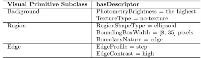
Table 3 shows an example of the image class definition at the perceptive level for the serous application. The image class is defined with instances of the visual primitives: region, edge, and background.
Table 3: Description of the serous application at the perceptive level with instances of visual primitive subclasses.
Visual Primitive Subclass hasDescriptor
Background PhotometryBrightness = the highest TextureType = no-texture
Region RegionShapeType = ellipsoid
BoundingBoxWidth = [8, 35] pixels BoundaryNature = edge
Edge EdgeProfile = step
EdgeContrast = high
4.2.4. Descriptor values
The descriptor values must allow for extensional and intensional defi- nitions. To this end, the model combines descriptors with numerical and symbolic values for the intensional definition, and descriptors with iconic values for the extensional definition:
• Numerical values are single values, interval of values, set of values, vector, and matrix of values (e.g., a geometrical distortion matrix).
• Symbolic values are conventional terms (e.g., RGB color space, Gaus- sian noise), qualitative terms (e.g., high, very-low), and superlative terms (e.g., the-least, the-most), which allow to express things like
“cell nucleus has a very low size” or “cell nucleus has the most area.”
• Iconic values are represented by entire image or blob file names (e.g., Illumination model).
4.3. Goal specification
The Goal class is described by the following three properties:
• hasTask identifies the currentTask to perform;
• hasControlConstrainttakes its values from the elements of theControlConstraint class.
• hasReferenceImage is a list of<TestImage, ReferenceImage> pairs.
Table 4 describes the “ObjectExtraction{serous cell nucleus}” objective of the serous cytology application.
Table 4: Specification of the “extract{serous cell nucleus}” objective.
Task ObjectExtraction{serous cell nucleus}
Optimization criterion Maximize hits
(acceptable error) (prefer false alarm to miss) Maximize boundary localization (prefer boundary inside the region) Detail Level Separate just touching
(acceptable error) (prefer no separation) Performance criterion Running-time≤2s Quality criterion Ability = reliability
4.3.1. Task concepts
Available tasks are subclasses of theTaskclass, such as: ColorEnhancement, EdgeDetection, ObjectExtraction, ObjectDetection, ImageDenoising, ImageSegmentation, etc. They are described by the following properties:
• hasArgument specifies the object of interest to which the task is applied if any (e.g., “ObjectExtraction {serous cell nucleus}”).
• hasDetailLevel is used to refine the scope of the task. Examples of DetailLevel subclasses are “do not affect the original color rank”,
“separate just touching objects”, or “separate all objects”.
• hasOptimizationCriterion is used to set the focus of attention of the task. Examples of OptimizationCriterion subclasses are ‘maximize boundary localization” or “maximize detection hits”.
Each subclass defines its own restrictions on the range of the proper- ties. For example, the ObjectDetection task has the following detail lev- els: Separation,NoSeparation, AllOccurrences, AtLeastOneOccurrence, BoundaryInside,BoundaryOutside, andSubPixelPrecisionLocalization.
In order to reach a compromise in case of doubt about compliance with constraints, each criterion to be optimized and each level of detail constraint can be associated to an AcceptableError by the hasAcceptableError prop- erty. For example, if there is a doubt about the fact that two objects are overlapping or just touching, an acceptable error for the “separate just touch- ing objects” constraint may indicate a preference for the “separation” or the
“no separation” of the related regions.
4.3.2. Control Constraint Concepts
The ControlConstraint class defines two types of constraints:
• The PerformanceCriterion class specifies processing time limits.
• The QualityCriterion class expresses requirements on the ability of the system to perform the task according to the specified and unspec- ified conditions. The two available ability values are reliability (i.e., prefer no result to bad result), and robustness (i.e., prefer bad result to no result at all).
5. Human-computer interaction model
In the previous sections, the kind of information required to develop im- age processing applications has been identified, and a domain ontology to represent them was proposed. This section deals with the ways and means to help users formulate application ontologies that correspond to concrete applications. The interaction between the users and the system takes place through a user interface that organizes the formulation cycle.
The interface is written in Java using Swing as the UI toolkit, and the ontology is handled thanks to the OWL API.
5.1. Formulation cycle
The formulation cycle is split up into five iterative steps derived from the formulation model exposed in Section 3:
1. The user formulates an initial representation of the objective, mainly extensional.
2. The system performs feature extraction from this extensional formula- tion and starts an intensional representation of the objective.
3. The user discards irrelevant features from the intensional representation and adds a list of representative test images to compose the first query.
4. Borg generates a software program and returns the images yielded by its execution on the test images, together with the features actually used by the reasoning engine as well as features it would have liked to use.
5. In case of unsatisfactory results, the user reformulates the objective by ruling out irrelevant features and by penalizing or favoring feature confidences. Then, the cycle goes back to step 4 until satisfaction.
5.2. Initial extensional formulation
The formulation system provides users with five frames dedicated to:
• the specification of the post-processing operations which aims at spec- ifying the context of use of the future software;
• the definition of the image class at the physical level;
• the definition of the image class at the semantic level or at the percep- tive level if the notion of object of interest does not make sense;
• the specification of the task with related constraints and the input of a set of reference images (when possible);
• and the determination of control constraints.
5.2.1. Specification of the post-processing operations
Post-processing refers to operations that will be performed on the results yielded by the image processing application. Post-processing information plays no direct part in the image processing formulation, but its purpose is to provide assistance later, during the task specification (see Section 5.2.5).
To specify post-processing operations, the interface displays a panel with 11 different post-processing categories: classification, image comparison, quan- tification, pattern recognition, registration, scene reconstruction, detection- tracking, art visualization, visual inquiry, transmission, and archival storage.
For each post-processing category, users can select operations among a prede- fined list (e.g., counting, printing, displaying, and measuring (size, position, orientation, radiometry, morphology, and topology)).
In the case of our running example, the “ObjectExtraction {serous cell nucleus}” task is followed by a classification of the extracted regions in order to detect abnormal or suspect cells. This classification is based on size, morphology, and radiometry measurements.
5.2.2. Physical definition of the image class
Users select the descriptors that best account for the effects of the acqui- sition chain on the visual appearance of the scene. All “physical descriptors”
defined by the Image Processing Ontology are displayed in a panel in the form of tables (See Figure 7). Users choose relevant descriptors and assign values with blobs or numerical values. In order to help users give numerical values, the system exploits a database that stores known descriptor values for some traditional acquisition systems.
For the “IlluminationCorrection” task of the cytology example, the cy- totechnologist has provided the definition given in Table 1. This definition combines symbolic and iconic descriptors.
Figure 7: The part of the interface that allows users to define the physical level of the image class.
5.2.3. Semantic definition of the image class
If the image class can be described at the semantic level, the definition relies on the construction of a tree of objects of interest. Indeed, a tree helps users determine the significance of a node according to its parent and siblings [45]. Four principles can be used to define objects organized in a tree: principles of similarity and difference with parents, and principles of difference and similarity with siblings. This allows adifferential definition of the objects: the description of an object is given in terms of its similarities and differences with other neighboring objects.
Figure 8: A serous cytology scene viewed through microscopic slides is composed of serous cells and red blood corpuscles scattered on mucous. A serous cell is composed of a nucleus surrounded by a cytoplasm. In this tree DC, EC, TPP, NTPP, and PO are the RCC-8 topological relations.
Users identify all objects of interest that may appear on images and or-
ganize them hierarchically by specifying the hyperonymic and meronymic relations between them:
• The hyperonymic relation “kind-of” defines a taxonomy of objects of interest based on similarities. This structure is the basis of two elemen- tary inferences that humans perform daily: identification, which is our ability to recognize the class of an object from its features, and spe- cialization/generalization, which is our ability to organize the objects in prototypical categories.
• The meronymic relation “part-of” describes the composition of these objects into entities and components, which can then be supplemented with extrinsic, distance, and topological spatial relations.
Based on the tree, users then describe each object of interest with relevant visual primitive descriptors using a differential definition.
Figure 8 is an example of the object tree defined for the serous application.
Table 5 gives an excerpt of a possible semantic definition for the objects. The {Serous cell nucleus} object is described with blobs whereas the {mucous}
object is described with linguistic values as the clearest region.
Table 5: Excerpt of the extensional definition of the serous image class at the semantic level for the segmentation task: ’ObjectExtraction{serous cell nucleus}’.
Object of Interest hasDefinitionElement hasDescriptor
Serous cell nucleus Region Model = . . .
Mucous Background PhotometryBrightness = the most (clearest) TextureType = none
5.2.4. Perceptive definition of the image class
If users choose to describe an image class at the perceptive level, the interface displays tables containing the symbolic descriptors associated to each visual primitive as defined in the ontology. Users can also provide several blobs for describing the different visual appearances of what they consider as a region, a background, a point of interest, an edge, etc.
The cytology application is described at the semantic level because all objects are predictable and describable. However, if we consider a hypo- thetical “ImagePartition” task, then the image class will be described at the perceptive level with several blobs, at least one for the each type of regions, edges and background (see Table 6).
Table 6: Excerpt of the extensional definition of the serous image class at the perceptive level for a hypothetical segmentation task: “ImagePartition”.
Visual Primitive Subclass hasDescriptor
Region Model = . . .
Background Model = . . .
Edge Model = . . .
5.2.5. Task specification
Users select the tasks to perform from a list provided by the interface, and if needed, the related argument within the list of the objects of interest.
When possible, users should add a list of reference images. These reference images are built with specialized interfaces (e.g., image manipulation software and interactive image segmentation system).
Then, users choose the related constraints from the list defined in the ontology. To that aim, the system uses post-processing information provided by users at the inception of the formulation process, to suggest some pos- sible constraints and related acceptable errors. This is done by using first order production rules. For example, since radiometric measurements are required during post-processing of the “ObjectExtraction” task, the system proposes the boundary localization as an optimization criterion with a re- lated acceptable error “prefer boundary inside” in order to avoid distorting the measurement results with boundary pixels:
(Goal(?x)∧ObjectExtraction(?y)∧hasT ask(?x,?y)∧
P ostP rocessingT ask(?z)∧hasM easurement(?z, radiometry)
→assert(BoundaryLocalization(?w))∧hasOptimizationCriterion(?x,?w)∧ hasAcceptableError(?w, pref er boundary inside))
5.2.6. Control constraints
Finally, users determine the type of optimization and ability required for the software solution through an appropriate frame.
5.3. First intensional formulation
Based on the initial formulation, the system builds an intensional formu- lation by extracting values from blobs and images given during the initial formulation. The list of descriptor values that can be extracted from blobs for each feature is prescribed in the ontology. For example, Table 7 gives an
excerpt of the list of region descriptor values that can be extracted from the blobs given for the extensional definition and presented in Table 6.
Table 7: Excerpt of the intensional definition of the{serous cell nucleus}concept after the feature extraction phase.
Object of Interest hasDefinitionElement hasDescriptor
Serous cell nucleus Region PhotometryBrightness = [38, 124]
PhotometryContrast = [12, 86]
ColorSaturation = [0, 0.609]
ColorHue = [3.53, 4.71] radians Convexity = [0.4, 0.9]
Rectangularity = [0.15, 0.81]
Area = [65.56, 179.67] pixels2 BoundingBoxWidth = [8, 35] pixels MajorAxisAngle = [0, 345] degrees CenterOfMass = [(10, 256), (5, 245)]
NumberOfHole = 0
Then, the formulation system invites users to correct their initial formu- lation by ruling out the descriptors they deem not relevant to the application.
For our example, we choose to rule out the descriptors in italic in Table 7.
As a matter of fact, serous cell nuclei are not characterized by their position, rectangularity, orientation, and number of holes. The intensional and the extensional definition together with test and references images compose the first query that is sent to Borg.
5.4. Program Generation
Borg exploits the intensional definition to perform abstract reasoning that supports the construction of the software program. The ontology elements are used notably to rate the knowledge source aptitude. Aptitude measures the distance between the ideal knowledge source application context and the given application context. For example, the aptitude of a knowledge source that suggests using an edge detection technique as part of the processing pro- gram is represented in Table 8. Each criterion is weighted with its importance in the aptitude rating. Borg computes the knowledge source credibility and plausibility against the current intentional definition using the Dempster- Shafer theory [46]. Then, depending on the control constraints selected by the user—reliability or robustness—Borg may decide to select the knowl- edge source to execute at each step of the resolution process only among the credible knowledge sources or also among the plausible ones.
5.5. Reformulation
During the reformulation process, most changes occur at the semantic level (or at the perceptive level) of the image class definition. After each pro- duction of a software program, the interface displays the resulting images,
Table 8: List of weighted criteria that defines the ideal application context of the knowledge source “Edge Detection.”
Criteria Importance
OptimizationCriterion=BoundaryLocalization high Noise.SignalNoiseRatio≥low very-high Noise.PowerSpectralDensity=white medium Background.TextureType= no-texture high
Edge.Contrast≥low high
Edge.Profile= step high
Edge.Orientation∈ {vertical, horizontal} low
the list of descriptors used by the software generator to determine its strate- gies and methods, and the descriptors the software generator would have liked to use. From this information, users can reformulate their problem by ruling out descriptors, adding new descriptors, and increasing or decreasing the confidence on descriptors through related user interfaces. When Borg receives the new query, it computes the new relative confidences for the de- scriptors before constructing a fresh solution. Consider a descriptor d, the new confidence value cd is updated as follows:
• +0.2, ifd is marked with ’+’ by user;
• −0.2, ifd is marked with ’−’ by user (if cd<0 then cd = 0);
• 0, otherwise.
Then, all descriptor confidences are normalized: ∀d, c′d= maxcd|c
d|.
A value of 0.2 in the domain [0.1] corresponds to a five point scale rating.
It is chosen experimentally. However, G. Miller in his seminal article [47]
justifies experimentally the use of seven point rating scales (plus or minus two) to absolutely rate the magnitude of unidimensional stimulus variables (e.g., auditory loudness, auditory pitch, saltiness) and thus image features.
In our example, the “ObjectExtraction {serous cell nucleus}” task gives rise to different solutions depending on the user preferences. If users give preference to edge features, an edge detection process will be used to extract the markers of the future regions followed by a watershed segmentation to locate region boundaries. If users give preference to region features and more particularly to color features, Borg will opt for a pixel classification based on color segmentation to extract the markers of the future regions before performing the watershed segmentation.
6. Experimentations and discussion
Trying to define quantitative measures to evaluate the formulation sys- tem is tricky since the experimental results widely depend upon the quality
of the knowledge stored in the knowledge base of the program generation system. So, as evaluation, we propose to investigate through experiments, first, the capacity of the system to represent different points of view on a same application, which lead to build different software solutions, second, the benefit of the interaction loop between the user and the system to build customized software programs, and third, the ability of the system to deliver effective services to users.
6.1. Capacity of representation
The capacity of representation is assessed by the ability of the language to express different definitions of a same objective that set forth the reasons justifying the design of various processing solutions described in the litera- ture. Prior to the experiments, the knowledge sources and image processing operators should be exhibited from the reverse-engineering of these solutions and introduced into the knowledge base.
Let us take another example in the domain of aerial imagery. The task is “ObjectExtraction {agricultural field}” with the optimization criterion
“maximize boundary localization”. Figure 9 shows a sample of the image class with the expected result, and Figure 10 shows the part of the applica- tion ontology representing the generic model of landscape scenes. For this ex- ample, we analyze four different solutions that give rise to two points of view on the definition of the objective. The differences between the various defi- nitions are essentially located in the semantic definition of the {agricultural field} object.
Figure 9: An example of the input image (a), and the expected result (b).
6.1.1. A first point of view
The definition of the {agricultural field} object of interest is viewed by some authors [48, 49] as a rather homogeneous region with contrasted bound- aries. They base their solution on a region growing method controlled by
Figure 10: The part of the application ontology representing the model of landscape scene.
edges. For instance, Butenuth et al. propose to use a watershed segmen- tation controlled by the gradient image, where the markers are the minima of the gradient image. They justify the use of this method by the fact that the field areas are rather homogeneous regions (T extureT ype= notexture;
P hotometryContrast≤low) and the field boundaries are highly contrasted (Contrast ≥ high). Mueller et al. propose to control the region growing with the edges extracted from a prior edge detection algorithm. They con- sider that the field boundaries are well defined, with high brightness contrast to neighboring regions (Contrast ≥ high) and relatively long and straight edges (Straightness ≥ high; Length ≥ medium). For both solutions, a second step is carried out to merge neighboring regions with low gray level differences and small regions into larger ones.
Butenuth et al. perform a final third step in order to fulfill the constraint
“maximize boundary localization”. They use the snake algorithm. The snakes are initialized as the smallest bounding rectangle of each extracted field since fields are polygonal regions often with four corners (Rectangularity >
medium). The external energy is the absolute value of the gradient since edges are contrasted (Contrast ≥ high) and the internal energy is set so as to favor rigidity because the field boundaries are described as long straight edges (Straightness > medium; Length > low).
6.1.2. A second point of view
The definition of the {agricultural field} object of interest is viewed by other authors [50, 51] as a region that can be discriminated from other re- gions by texture and color features. This new point of view leads to use a statistical approach based on supervised pixel classification. Dubuisson-Jolly and Gupta propose to use maximum likelihood classification that combines texture (T extureScale = micro; T extureT ype =complex) and color infor- mation (ColorSaturation). Xu et al. opt for a SVM approach for pixel
classification based only on texture information. Both methods use blobs to train the related classifier (M odel :blobs).
6.1.3. Definition at the semantic level
During the formulation cycle, if the user considers that{agricultural field}
object is characterized by its inner homogeneity and high contrasted bound- ary, he provides a semantic definition close to the one given in Table 9. If the user provides blobs, the values are set automatically at the feature extraction stage. The definition thus contains all the information that motivates the use of a solution based on a region growing approach: the regions are non- textured areas with a known minimum area and low photometry contrast, and their boundaries are long straight edges. Actually, Borg chooses the Buthenuth’s solution because it is regarded as more stable than the second one (edge detection is known to be an unstable process). But, if the user gives higher confidence to the edge descriptors of the same formulation, then Borg will select the Mueller’s solution. Conversely, if the user gives preference to the region descriptors then Borg will choose the first one.
Table 9: A semantic definition that supports the use of the region growing approach.
Object of Interest hasDefinitionElement hasDescriptor
Field Region (field area) TextureType = no-texture PhotometryContrast = [0, 27]
Rectangularity = [0.57, 1.0]
Area = [623, 120904] pixels2 BoundaryNature = edge Edge (field boundary) Profile = step
Contrast = [0.11, 0.27]
Sharpness = [0.82, 0.98]
Straightness = [0.7, 1.0]
Length = [143, 634] pixels
If the user sees the {agricultural field} object as a textured region than he provides a semantic definition such as the one in Table 10. This defi- nition contains all necessary information that favors the use of a statistical approach, given that the object is characterized by complex micro texture (T extureScale = micro; T extureT ype = complex) and color saturation (ColorSaturation = [0.220,0.467]), and that the definition provides several blobs as examples of real appearances (M odel : blobs). The Xu’s solution is chosen when the user has little confidence in the color features; otherwise the Dubuisson-Jolly’s solution is selected because it involves more a priori information.
We have shown in this example that the ontology is able to represent two different points of view on the same object, which provide the information necessary to the selection and parameterization of different solutions. This

![Figure 3: A simplified textual representation of the definition of a pollen grain of type poaceae using the concepts available in the visual concepts ontology proposed by [20].](https://thumb-eu.123doks.com/thumbv2/1bibliocom/470617.74340/9.892.203.678.320.438/simplified-representation-definition-concepts-available-concepts-ontology-proposed.webp)