HAL Id: hal-00003124
https://hal.archives-ouvertes.fr/hal-00003124v4
Preprint submitted on 8 Apr 2005
HAL is a multi-disciplinary open access archive for the deposit and dissemination of sci- entific research documents, whether they are pub- lished or not. The documents may come from teaching and research institutions in France or
L’archive ouverte pluridisciplinaire HAL, est destinée au dépôt et à la diffusion de documents scientifiques de niveau recherche, publiés ou non, émanant des établissements d’enseignement et de recherche français ou étrangers, des laboratoires
Lithium atom interferometer using laser diffraction : description and experiments
Alain Miffre, Marion Jacquey, Matthias Büchner, Gérard Trénec, Jacques Vigué
To cite this version:
Alain Miffre, Marion Jacquey, Matthias Büchner, Gérard Trénec, Jacques Vigué. Lithium atom interferometer using laser diffraction : description and experiments. 2005. �hal-00003124v4�
ccsd-00003124, version 4 - 8 Apr 2005
Lithium atom interferometer using laser diffraction: description and experiments
A. Miffre, M. Jacquey, M. B¨uchner, G. Tr´enec and J. Vigu´e Laboratoire Collisions Agr´egats R´eactivit´e -IRSAMC
Universit´e Paul Sabatier and CNRS UMR 5589 118, Route de Narbonne 31062 Toulouse Cedex, France
e-mail: jacques.vigue@irsamc.ups-tlse.fr (Dated: April 8, 2005)
Abstract
We have built and operated an atom interferometer of the Mach-Zehnder type. The atomic wave is a supersonic beam of lithium seeded in argon and the mirrors and beam-splitters for the atomic wave are based on elastic Bragg diffraction on laser standing waves at λ = 671 nm. We give here a detailed description of our experimental setup and of the procedures used to align its components. We then present experimental signals, exhibiting atomic interference effects with a very high visibility, up to 84.5±1 %. We describe a series of experiments testing the sensitivity of the fringe visibility to the main alignment defects and to the magnetic field gradient.
PACS number: 39.20.+q, 03.75.Dg, 32.80Lg
I. INTRODUCTION AND BRIEF HISTORICAL OVERVIEW
We have built a Mach-Zehnder atom interferometer, which gave its first signals in 2001 [1]. In this interferometer, the atomic wave is a supersonic beam of lithium seeded in argon, with a lithium de Broglie wavelength λdB = 54 pm. Coherent atom manipulation is based on Bragg diffraction on quasi-resonant laser standing waves at a wavelength λL ≈ 671 nm.
We use elastic laser diffraction, which can be made with ordinary single frequency lasers, because this process has little sensitivity to the phase noise of the laser beams. However, the associated difficulty is that the output atomic beams differ only by their directions of propagation and not by their internal states. Therefore, such an interferometer must be operated with a highly collimated atomic beam resulting in a strongly reduced output atomic flux. Fortunately, the transmission of such a Bragg Mach-Zehnder interferometer is quite high and, thanks to an intense lithium beam and a very sensitive hot-wire atom detector, we obtain reasonably large signals. Moreover, we have been able to observe interference signals while using the diffraction orders p= 1, 2 and 3 and in the case of the first order, the signal exhibits an excellent fringe visibility V = 84.5±1 %.
We may recall the development of atom interferometry since 1991, when several atom interferometers gave their first signals:
• a Young’s double slit experiment by O. Carnal and J. Mlynek, with a supersonic beam of metastable helium [2]
• a Mach-Zehnder interferometer by D. Pritchard and co-workers using a thermal atomic beam of sodium and diffraction on material gratings [3]
• a Ramsey-Bord´e interferometer by J. Helmcke and co-workers, with a thermal atomic beam of calcium, was used to demonstrate Sagnac effect with atomic waves [4]
• an atom interferometer using Raman diffraction by M. Kasevich and S. Chu, with cold sodium atoms, was used to make the first high sensitivity measurement of the local acceleration of gravity by atom interferometry [5]
This research field has been rapidly expanding since 1991 and an excellent overview of this field and of its applications can be found in the book ”Atom interferometry” [6] published in 1997. Many types of atom interferometers have been developed and we limit the present review to the apparatuses in which the atomic paths are noticeably different, i.e. we will not discuss the interferometers, such as atomic clocks, in which the momentum transfer is very small. Moreover, we limit our review to interferometers operating with thermal atoms or molecules, quoting only the first publication for each interferometer. In addition to the interferometers built in 1991, we find: a magnesium atom interferometer by W. Ertmer and co-workers [7]; a calcium atom interferometer by A. Morinaga and co-workers [8]; an I2
molecular interferometer by Ch. J. Bord´e and co-workers [9]; a Na2molecular interferometer by D. Pritchard and co-workers [10]; a metastable argon interferometer of A. Zeilinger and co-workers [11]; a metastable neon interferometer by Siu Au Lee and co-workers [12]; a cesium atom interferometer gyroscope by M. Kasevich and co-workers [13]; a K2 molecular interferometer by E. Tiemann and co-workers [14], a helium atom and dimer interferometer by J. P. Toennies and co-workers [15], a large molecule interferometer by A. Zeilinger and co-workers [16]; a metastable hydrogen interferometer by T.W. H¨ansch and co-workers [17].
In this paper, we recall the principles of Mach-Zehnder atom interferometers and of laser diffraction. Then, we explain our basic choices and we describe our setup and its alignment
procedures. We present a diffraction experiment, used to choose the parameters of the laser standing waves, and a set of interference signals recorded using the diffraction orders p= 1,2,3. We explain how we have optimized the fringe visibility by a systematic study of its variations with the main defects of the interferometer.
II. MACH-ZEHNDER ATOM INTERFEROMETERS: GENERAL PROPERTIES AND OUR DESIGN
A. General properties
A Mach-Zehnder grating interferometer is derived from the optical Mach-Zehnder inter- ferometer by replacing the beam-splitters and mirrors by diffraction gratings. This interfer- ometer was developed with X-rays [18] in 1965, with neutrons [19] in 1974 and with atoms [3, 5] in 1991. Figure 1 presents a schematic drawing of the atom paths in such an interfer- ometer. In the simplest approximation, the incident atomic wave is treated as a plane wave Ψ(r) = exp [ik·r] and diffraction of order pby grating Gj produces also a plane wave:
Ψd(r) = αj(p) exp [ik·r+ipkGj ·(r−rj)] (1) Conservation of energy and momentum must be fulfilled and equation (1) is exact only in the case of Bragg diffraction but, near this geometry, it is valid up to the first order in power of kGj/k. αj(p) is the diffraction amplitude of order p by grating Gj. The wave vector kGj of gratingGj lies in the grating plane, perpendicular to its lines, with a moduluskGj = 2π/a (a is the grating period, assumed to be the same for the three gratings). rj measures the position of a reference point linked to grating Gj. As shown by equation (1), the phase of the diffracted beam depends rapidly on the position of the grating in its plane. The output beam labeled B1 in figure 1 results from the interference of two waves Ψu (following the upper path with the diffraction orders p, −p and 0) and Ψl (following the lower path with the diffraction orders 0, p and −p):
Ψu/l(r) = au/lexphik·r+ϕu/l
i (2)
with au = α1(p)α2(−p)α3(0) and al = α1(0)α2(p)α3(−p) while ϕu = p[kG1·(r−r1)−kG2·(r−r2)] and ϕl = p[kG2·(r−r2)−kG3·(r−r3)]. These two waves interfere on the detector and the resulting total intensity is given by integrating over the detector surface:
I1 =
Z
d2r|Ψu+ Ψl|2 =
Z
d2rha2u+a2l + 2aualcos (ϕu −ϕl)i (3) To simplify the algebra, we have assumed that the amplitudesau and al are real. The phase (ϕu−ϕl) is given byϕu−ϕl =p[∆kG·r+ ∆ϕG] where ∆kG is given by:
∆kG=kG1+kG3−2kG2 (4)
and the phase ∆ϕG is a function of the grating positions only:
∆ϕG = [2kG2·r2−kG1·r1−kG3·r3]≈kG(2x2−x1−x3) (5)
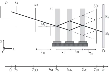
FIG. 1: Schematic drawing of our Mach-Zehnder interferometer (top view). The x, y, z axis are represented and we give the distance z of each element to the nozzle. O : lithium oven; Sk : skimmer at zs = 20 mm ;S0: first collimating slit at zS0 = 485 mm;S1: second collimating slit at zS1 = 1265 mm;Mi,i= 1−3 : mirrors for the laser standing waves atzM1= 1415 mm,zM2= 2020 mm andzM3 = 2625 mm;B1and B2: complementary exit beams; SD: detector slit with a tunable width atzSD= 3025 mm ; D: 760µm wide rhenium hot wire of the Langmuir-Taylor detector at zD = 3375 mm. We have also represented the main stray atomic beams produced by diffraction on the three gratings, assuming that only two diffraction orders, 0 and p are produced, as in the ideal Bragg regime.
Fringes appear over the detector area if the condition ∆kG = 0 is not fulfilled. In the experiments, this condition is verified by tuning the orientation of one grating in its plane and any small deviation induces a large visibility loss, as shown below (see figure 5). The x-positions of the three mirrors change the phase ∆ϕG of the atom interference fringes. This property provides a very convenient method to sweep the interference fringes: this phase is non-dispersive, i.e. independent of the velocity of the atomic wave, so that there is no associated visibility loss. If we assume that ∆kG = 0, then |Ψu+ Ψl| is independent of r and the intensity I1 of the exit beam B1 is proportional to:
I1 =a2u+a2l + 2aualcos(ϕu−ϕl) =I1,m[1 +Vcos(ϕu−ϕl)] (6) where V is the fringe visibility given by:
V = 2aual
a2u+a2l = 2√ρ
1 +ρ (7)
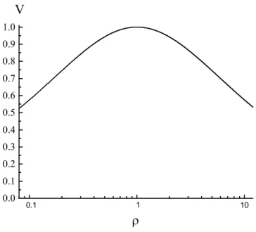
where ρ is the ratio of the intensities carried by the two interfering beams, ρ=a2u/a2l. The visibility V, which is a symmetric function of au and al, has the same value if ρ is replaced by its inverse. A small amplitude mismatch reduces the visibility but only very slightly, as shown in figure 2.
0 .0 0 .1 0 .2 0 .3 0 .4 0 .5 0 .6 0 .7 0 .8 0 .9 1 .0
V
0.1 1 10
FIG. 2: Fringe visibility V for a two-beam interference as a function of the intensity ratio ρ. A logarithmic scale has been used for ρ so as to exhibit the symmetry whenρ is replaced by 1/ρ.
B. Our main choices
Our goal was to build an atom interferometer in which the two atomic paths are suffi- ciently separated, so that one can apply a perturbation to only one path: such an arrange- ment is necessary to perform interferometric measurements of a perturbation. Previous experiments of this type include the measurement of the electric polarizability of sodium [20, 21] and the measurement of the index of refraction of gases for sodium atomic waves [22, 23], both experiments being done by D. Pritchard and co-workers. More recently, J.
P. Toennies and coworkers have compared the electric polarizability of helium and helium dimer [24]. Moreover, we wanted to observe the dependence of the index of refraction with the velocity of the atomic wave and this dependence is detectable only if this velocity is comparable to or larger than the thermal velocity of the target gas. We have therefore cho- sen to use for the atomic wave a thermal beam rather than a slow beam: this second choice would have imposed to use also a cold atomic target, making the experiment very complex.
We had to choose the diffraction process, among several possibilities: diffraction by mate- rial gratings (which was first studied by D. Pritchard and co-workers [25] and briefly reviewed in reference [26]), elastic diffraction by a laser standing wave (first observed by Arimondo et al. [27], with well resolved diffraction peaks first recorded by D. Pritchard and co-workers [28]) or inelastic diffraction processes, which can be either a one-photon diffraction process (used in Ramsey-Bord´e interferometers) [4], or a two-photon Raman diffraction process used in many cold or thermal atom interferometers (its first use being described in reference [5]).
We have chosen to use elastic Bragg diffraction by laser standing waves, the main advantages being the high transmission of the interferometer associated with a high fringe visibility and the fact that we can use an ordinary single frequency laser. The first interferometers using this diffraction process and thermal atoms were built by Siu Au Lee and co-workers with metastable neon [12] and also by A. Zeilinger and coworkers using metastable argon (but not
in the Bragg regime) [11]. Elastic diffraction is similar to diffraction by a material grating, in the sense that the internal atomic state is not modified. The grating period is equal to half the laser wavelength, which must be chosen very close to a resonance transition of the atom, so that diffraction can be observed with modest laser power densities. With sufficient laser power densities, diffraction orders higher than the first one can be easily observed [29, 30, 31].
The choice of laser diffraction limits the choice of the atom among those which have an intense resonance transition accessible to cw single frequency lasers. If one excepts the use of metastable states (with rare gases or hydrogen), this requirement favors considerably the alkali atoms. Then, the most important quantity is the Bragg angle θB = λdB/λL, which must be as large as possible in order to maximize the separation between the two atomic paths in the interferometer. Because the atomic de Broglie wavelength scales like m−1, a light atom is favored and we have chosen the lithium atom. Its first resonance transition is at a 671 nm wavelength, corresponding to a grating perioda= 335 nm. By seeding lithium in a supersonic beam of argon, the mean velocityuof the lithium atoms is close to 1060 m/s corresponding to a de Broglie wavelength λdB = 54 pm and a Bragg angleθB = 80 µrad.
C. Elastic diffraction of atoms by a laser standing wave
As pointed out by Siu Au Lee and coworkers [12], diffraction in the Bragg regime is ideal to build an interferometer: only two diffraction orders (0 and p) are produced for a well chosen incidence angle and, by varying the laser power density and/or the interaction time, the diffraction efficiency can be tuned to produce 50−50% beam-splitters and 100% mirrors.
Therefore, the transmission of an ideal Mach-Zehnder interferometer using this diffraction process should be equal to 100% and, as a result of the symmetry of this interferometer, the fringe visibility, measured on the B1 output beam, should also be equal to 100 %.
We first recall that elastic diffraction by a laser standing wave results from the absorption of a photon going in one direction followed by the stimulated emission of a photon going in the other direction: this scheme corresponds to first order diffraction andpsteps are needed for the diffraction order p. After an absorption-emission cycle, the atom is back in its initial level, and it has received a momentum kick equal to two photon momenta.
The laser frequency ωL and the resonance atomic frequency ω0 differ by the detuning δ =ωL−ω0, which must be considerably larger than the natural width γ of the resonance transition. Then, the main effect of the laser standing wave is to create a weak periodic potential proportional to the local density of energy in the laser beam, V =V0(z) cos2(kLx) (where the x axis is parallel to the laser beam wave vector). The periodic nature of the potential can be treated by introducing Bloch states as done in our previous paper [32], which quotes many previous works on laser diffraction.
To simplify the discussion, we assume that V(z) extends over a distance w (we do not define precisely w which should not confused with the Gaussian beam radius w0 discussed below), so that an atom with a velocityv interacts with the laser beam during an interaction timetint=w/v. The natural energy unit of the problem is the atomic recoil energy ¯hωrec= (¯hkL)2/(2m). Following [32, 33], this quantity can be used to define a dimensionless potential q=V0/(4¯hωrec) and a dimensionless interaction time τ =ωrectint.
The incident atom is characterized by its momentum state in thexdirection, |kxi. When q is large (q ≫ 1), the periodic potential couples the incident atomic wave |kxi to many other states |kx+ 2nkLi, where n is an integer. The Bragg regime occurs when kx ≈ ±pkL
and if the potential qis not too strong and does not vary too rapidly with z. Then, one can neglect the coupling of the two states|kx =±pkLiwith other states and treat the dynamics as a two-level problem. At the lowest nonvanishing order, the coupling between these two levels is proportional to qp and the probability of diffraction of order p is then given by a Rabi oscillation:
Pp = sin2(qpτ /dp) (8)
where the coefficientdp is equal to 1 for orderp= 1, to 4 for orderp= 2 and to 64 for order p = 3. The intensity which is not diffracted remains in the zeroth-order beam. Because of the dependence in qp of the sine argument in equation (8), the q values for a 50−50%
beam-splitter and a 100% reflective mirror are linked by qBS = qM ×2−1/p. Finally, this diffraction process induces some phase-shifts of the waves which will not discussed here but which may be very important [34].
If δ is too small, real excitation of the atom followed by a spontaneous emission of a photon occurs during the time spent by the atom in the laser field. When this occurs, the coherence of the atomic propagation is destroyed very efficiently. The probability PSE of a spontaneous emission event is given by :
PSE =qτγ
δ (9)
As q ∝ δ−1 and PSE ∝ δ−2, laser diffraction can be made almost perfectly coherent by choosing a sufficiently large detuning. For a given value of q, the use of a larger detuning requires also a larger laser power density, so that the available laser power gives a practical limit to the detuning.
III. EXPERIMENTAL SETUP
Our experimental setup is inspired by the sodium interferometer of D. Pritchard and co-workers [35] and by the metastable neon interferometer of Siu Au Lee and co-workers [12]. We are going to describe its main parts and to explain our procedures to align its components.
A. Vacuum system
The vacuum system is made of five differentially pumped chambers, (see figure 1):
• the first chamber contains the supersonic beam source and is pumped by a 8000 l/s unbaffled oil diffusion pump (Varian VHS400). The gas load due to the beam is a few mbar.l/s and, under normal beam operation, the residual pressure is about 8×10⁻⁴ mbar. The beam exits this chamber through a 0.97 mm diameter skimmer provided by Beam Dynamics.
• the second chamber, which serves to differential pumping, to collimation and to optical pumping of the lithium beam, is pumped by a 2400 l/s oil diffusion pump (Varian VHS6) with a water cooled baffle. Under normal beam operation, the pressure is about 3×10⁻⁶ mbar. The beam exits this chamber through the source slit S0.
• the third chamber, which serves to collimation only, is pumped by a 700 l/s oil dif- fusion pump from Edwards with an internal baffle. The residual pressure is below 5×10⁻⁷ mbar, practically independent of beam operation. The beam exits this cham- ber through the collimation slit S1.
• the fourth chamber, which contains the interferometer, is pumped by two 1200 l/s oil diffusion pumps (Varian VHS1200) with water cooled baffles. The residual pressure is below 5×10⁻⁷ mbar. The detector slit SD is also located in this chamber. The beam exits this chamber through a 3 mm diameter hole, located just before an UHV gate valve.
• the fifth chamber holds the surface ionization hot-wire detector. As the stray signal of such a detector is very sensitive to the residual gas, this chamber is built with UHV components and is pumped by a 300 l/s turbo molecular pump. The residual pressure in this chamber is a few 10−9 mbar, when the UHV gate valve is closed and about 10−8 mbar when it is opened.
All the water baffles are cooled by circulating a liquid near 3◦C. We use three double stage roughing pumps: two 65 m3/h pumps, one for the beam source, one for the other four oil diffusion pumps and a 15 m3/h pump for the turbo pump of the detector. To reduce vibrations induced in the setup, these pumps are located in the next room.
B. The atom wave source and detector
Our lithium atomic beam, inspired by the design of Broyer, Dugourd and co-workers [36]
is briefly described in [1, 37, 38] and more details will appear in another paper. Lithium is seeded in argon and our normal operating conditions are a source pressure of 330 mbar, a temperature equal to 973 K for the back part of the oven (fixing the lithium vapor pressure near 0.55 millibar), a temperature equal to 1073 K for its front part and a nozzle diameter equal to 200µm. We have measured the beam mean velocity,u= 1060 m/s and the terminal parallel temperature of lithium Tk ≈6.6 K. This parallel temperature is roughly 1/3 of the calculated parallel temperature of the argon carrier gas, an effect which occurs when a light species is seeded in a heavier carrier gas [37, 38].
To detect the output beams, we use a hot-wire detector which has been fully described in a previous study [39]. Its detection efficiency, which varies with the oxidation and the temperature of the rhenium wire, was measured to be close to 30%. With our normal operating conditions, the collimated beam gives a signal up to 8×10⁴ counts/second, on a background signal close to 2× 10³ counts/second. This background signal presents a non-Poissonian statistics with a few bursts.
On figure 1, it is clear that the location of the detector must be well chosen. We must put the detector far enough from the third laser standing wave, at a place where the two exit beams B1 and B2 are well separated: these beams carry complementary signals and the fringe visibility would be very small if the detector was put close to the third grating, where these two beams are strongly overlapping. The complementary character of the two signals is a consequence of the fact that laser diffraction is acting on the phase and not on the amplitude of the atomic wave (for more details, see figure 7 of reference [40]). However, we must not forget the existence of the stray beams represented on figure 1. These beams carry some flux, because the diffraction amplitudes are not at their optimum values, and
these stray beams cross the main exit beams B1 and B2 at a distance equal to the inter- grating distance L12 = L23 = 0.605 m. Therefore, we have chosen to put the detector slit (which defines if an atom is detected or not) at a distanceL34= 0.40 m from the third laser standing wave, 0.2 m in front of the place where these stray beams are expected to create the largest signals. The hot wire itself is 0.35 m away in the fifth UHV vacuum chamber.
In a first arrangement, the detection slit, which was placed very near the hot wire detector, was put out of order by excessive heating due to the hot wire radiation.
C. Laser standing waves
We use an home-made single frequency cw dye laser, following F. Biraben’s design [41], pumped by a Spectra-Physics argon ion laser at 515 nm. The dye is LD 688 from Exciton dissolved in EPH. Using the H¨ansch-Couillaud [42] frequency stabilization, we get a laser linewidth of the order of 1 MHz. The laser beam goes through a 60 dB optical isolator.
After the isolator, the power available at 671 nm is close to 400 mW, for 5 W of Ar+ pump power.
The laser frequency, which is measured by a home-made lambdameter, must be detuned from resonance, which has a complex structure due to the fine, hyperfine and isotopic split- tings [43]. Most of our experiments are optimized for the 7Li isotope (natural abundance 92.5%) and we define the frequency detuning by:
δ/(2π) =νL−E(2P3/2)−E(2S1/2, F = 1)/h (10) where the energies are those of the 7Li isotope levels. The hyperfine structure of the 2P3/2
state is very small and can be neglected. Our usual choice of detuning is δ/(2π) = +3.0 GHz and whenever a different value is used, it will be indicated. The natural width of the
2S1/2 -2P3/2 transition of lithium is γ/2π = 5.9 MHz [44].
The laser beam is magnified by a telescope made of two AR coated singlet lenses so that we can change the magnifying ratio by changing one lens. We characterize the beam transverse profile by scanning a photodiode through it, thanks to a motorized translation stage, and the recorded intensity as a function of the photodiode position is fitted to a Gaussian profile, thus extracting the Gaussian beam radius w0. When operating with low power densities (practically only when using first order diffraction), the Gaussian beam is limited by an iris and the resulting beam profile is closer to a flat top profile.
The beam is then split by two beam splitters with a nominal transmission equal to 50%
for an incidence of 45◦. We thus get three beams, one with a power close to P/2 and two beams, each with a power close to P/4. The P/2 beam serves for the central laser standing wave, on mirror M2, while the two P/4 beams serve for the other laser standing waves, on mirror M1 and M3. Using incidence angles different from 45◦, we are able to modify the power repartition between these three beams: this is needed when using first order diffraction because the real transmission differs from 50% and also when using higher diffraction orders p = 2 and 3, because the needed power repartition is not the same. In order to choose the best laser power repartition, we have recently installed attenuators made of an half-wave plate followed by a polarizer on two of these three laser beams. This system was not available during most of the experiments described here.
The three laser beams are sent near normal incidence on the mirrors Mj. The properties of a standing wave are weakly sensitive to the exact value of the incidence angle on the mirror
and very sensitive to the orientation of the direction perpendicular to the mirror surface.
More precisely, if a plane wave is incident on a mirror with a small angle of incidence i, the reflected wave and the incident wave produce a wave which is progressive in a direction parallel to the mirror surface, with a wave vector kLsini and which is a standing wave in the direction normal to the mirror with a wave vector kLcosi. The progressive character of the wave parallel to the mirror surface induces a Doppler shift of its frequency equal to kLusini which corrects the detuning: in our experiment, this Doppler shift of the order of 1.5 MHz per mrad is perfectly negligible. The fact that the laser wave vector normal to the mirror surface is kLcosi slightly modifies the momentum kick received by the atoms which becomes 2pkLcosi but, for small i values, this modification is negligibly small.
Following equation (6), the phase of the interference fringes depends on the x-positions of the three mirrors and this property makes the interferometer very sensitive to vibrations. In the interferometers developed by D. Pritchard [35] and by Siu Au Lee [12], these vibrations were controlled by servo-loops. We have chosen to minimize these vibrations by building a very rigid rail to support the three mirrors Mj. This rail and the role of vibrations will be discussed in an other paper. As in references [12, 35], we use an optical three-grating Mach-Zehnder interferometer to control the vibrations of thex-positions of the three mirrors Mj and the measured noise on the quantity (2x2−x1−x3) is negligibly small, with a rms amplitude of the order of a few nanometers. The output signal of this interferometer is also used to calibrate the displacement of the motion of the mirror M3, which serves to observe interference fringes.
D. Alignment procedures
We must align the atomic beam and the mirrors producing the laser standing waves. The numerous adjustments must be done with great care: to give an idea, most angles must finally be tuned within about 10 µrad from their optimum value.
The atomic beam alignment is difficult as the beam must go with minimum attenuation from the nozzle to the hot-wire of the detector 3.4 m away, through the skimmer, the source slit S0, the collimation slitS1, the detector slit SD, the 3 mm diameter hole located before the detector chamber. For each element, we explain the available adjustments and how we proceed to make them:
• the oven can be adjusted in the three directions under operation.
• the skimmer and the 3 mm diameter hole are fixed to the center of their supporting flanges, while all the other elements can be adjusted in the xdirection, but not in the y direction. This is possible because the three slits have a sufficient height, about 10 mm.
• the width of the slitS0 is fixed and equal to 20µm, while the widths of the collimation slitS1 and of the detector slitSD are controlled by piezo-drives from Piezosystem Jena in the 0−200 µm range: the slit widths commonly used are e1 = 12 µm for S1 and eD = 50 µm for SD (if different values are used, they will be specified). The slit material has been chosen to be non magnetic, because the inhomogeneous field which would exist in the slit opening could induce a spreading of the atomic beam, by Stern and Gerlach effect.
• the slits S0, S1 and SD are made vertical before operation. We have used either the diffraction pattern of a laser beam or the observation of the slit with a telescope, in comparison with a plumb line. We estimate that the slits are vertical within a few mrad: if the useful height of the slit Si is hi, a small error ǫon its verticality induces no broadening of the full width at half maximum of the beam but a broadening of its wings of the order of ǫhi. We can evaluate these useful heights simply by assuming straight lines trajectories for the atoms, from the skimmer to the 3 mm hole near the detector. The calculated useful height is 1.3 mm range forS0, 1.8 mm for S1 and 2.9 mm for SD. The corresponding broadening of the beam wings, of the order of 1−3 µm per mrad, is probably fully negligible for S0 and SD which are rather wide, and less negligible forS1 which has usually the smallest width.
• the x-position of these three slits and of the hot-wire can be modified under vacuum:
in each case, we use a translation stage operated by a linear drive vacuum feedthrough, with a sensitivity of the order of 10 µm. In addition, the x-position of the detector slit SD can be swept under computer control by a piezo-translation from Piezosystem Jena over 400 µm.
For the laser standing waves, each mirrorMj is attached to a double stage kinematic mount built in our laboratory. The first stage, with screws, can be operated only when the ex- periment is at atmospheric pressure while the second stage actuated by low-voltage piezo- translators, has a tuning range close to 600µrad. A first alignment, within±100µrad, must be made with the experiment at atmospheric pressure and the final tuning is made with the second stage. To make the first alignment, we use the following signals:
• we first adjust the rotation θz around the horizontal axis z with an autocollimator.
For each mirror Mj, we set the autocollimator by observing the horizontal surface of diffusion pump oil through a pentaprism and we set the mirror perpendicular to the autocollimator axis.
• we then adjust the rotation θy around the vertical axis y, with a laser beam which replaces the atomic beam, going from the skimmer to the 3 mm hole near the detector.
Then, using a pentaprism, we send this beam successively on each mirrorMjand we set the mirror so as to maximize the reflected laser power measured behind the skimmer.
With the experiment under vacuum, we make the final adjustment of θy for each mirror Mj: we tilt the mirror to observe Bragg diffraction of the chosen orderp(see figure 3) with the corresponding laser standing wave. We have no signal which can be used to finely tune the θz angles separately, but we must tune one of these three angles to cancel ∆kG defined by equation (4) and the fringe visibility is very sensitive to an exact cancellation, as shown below in figure 5. We use mirrorM2 as its effect is twice as large as the effect ofM1 or M3. Finally, an optical grating is linked to each mirrorMj to form the optical three-grating Mach-Zehnder interferometer briefly discussed above. It is necessary to align this interfer- ometer before the final adjustments of the mirrors Mj.
IV. ATOM INTERFERENCE EFFECTS A. Diffraction experiments
With only one laser standing wave, we can observe diffraction. Two main types of diffrac- tion experiments have been done:
• by setting the orientation of the mirror in order to be in the Bragg geometry, we produce a diffracted beam. Then, by scanning the position of the detector slit, we can record the profile of the direct and diffracted beam. A typical result was shown in our previous paper [1]. We have verified that the diffraction behaves as expected in the Bragg regime, with, in particular, the absence of a beam of order p = −1 when the geometry favors the diffraction of order p= 1.
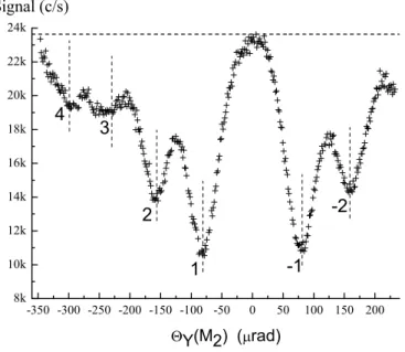
• by rotating the mirror around the y-axis, we successively fulfill the Bragg condition for the various diffraction orders p. We have recorded the direct beam intensity as a function of the angle θy and diffraction then appears as an intensity loss. Figure 3 presents such a recording. We observe intensity losses corresponding to Bragg condi- tion for the ordersp=−2 up top= 4. The interest of such a recording is that it gives immediately an idea of the diffraction efficiency. We never reach a 100% diffraction probability, because of the presence of 6Li and of the finite widths of the velocity and angular distributions of the incident atomic beam.
With our usual detuning δ/(2π) = 3.0 GHz and with the typical power density used for first order diffraction, the diffraction probability for the 6Li atoms is very small and we may forget their presence. We have also made some experiments with a detuning chosen to diffract selectively these atoms.
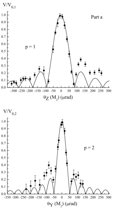
B. High visibility atom interference fringes
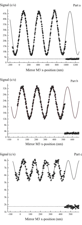
We have operated our interferometer using successively three different diffraction orders p = 1, 2 and 3. By sweeping the x-position of mirror M3, we have observed interference signals with a very high visibility which are plotted in figure 4. In all cases, the signal is expressed as a number of atoms detected per second with an usual counting time equal to 0.1 s. The observed signal can be written as:
I1 =IB+I0[1 +Vcosφ] (11) The background signalIBof the detector is recorded just after or before recording the signals, by flagging the atomic beam in the second chamber and we deduce from this measurement the mean IB value. Then, we can make a fit of the signal to estimate the mean intensity I0
and the visibility V. The phase φ is a locally linear function of time, but the fit must take into account the nonlinearity of the piezo drive. Table I gives for the three orders p= 1, 2 and 3 the parameters used (laser detuning, beam waist w0 and beam powers) and the mean intensity I0 and the visibility V deduced from the fits.
We have measured the interferometer transmission by making the ratio of the intensity at the peak of constructive interference and of the intensity of the direct atomic beam, in the absence of the three laser standing waves. With first order diffraction, the measured
-350 -300 -250 -200 -150 -100 -50 0 50 100 150 200 8k
10k 12k 14k 16k 18k 20k 22k 24k
-2
-1 2
1 3
Signal (c/s)
4
Y (M
2
) ( rad)
FIG. 3: Intensity of the direct beam measured as a function of the angle θy of mirror M2. When the Bragg condition is fulfilled for a diffraction order p, the transmitted intensity goes through a minimum labelled by the order p. This experiment was made with an almost Gaussian laser beam with a measured waist radius w0 = 3.1 mm, a power P = 240 milliwatts and a detuning δ/(2π) = 1.2 GHz. The collimation slit width wase1 = 10µm and the detection slit was eD = 70 µm.
transmission can reach quite large values, up to 85%. Theory predicts a 100% value and the difference is due mainly to imperfections of the diffraction process and to the presence of 6Li in the beam with its natural abundance equal to 7.5%.
The dependence of the fringe visibility with the diffraction order has been studied only once before, by Siu Au Lee and coworkers [12]: in this experiment like in the present case, the visibility decreased rapidly with increasing order: V = 62% forp= 1,V = 22% forp= 2 and V = 7% for p= 3. The most natural explanation of this rapid decrease is the existence of a phase noise with an amplitude proportional to the diffraction order p: this is the case if the phase noise comes from the grating vibrations. However, two other effects may also contribute to the rapid decrease of the fringe visibility when the order pincreases:
• the incoherent processes involving a real photon absorption followed by spontaneous emission are not negligible with the power densities used for ordersp= 2 or 3
• the diffraction phase-shifts [34] behave like q2τ and may be rather large during the diffractions of orders p= 2 or 3. A large phase shift does not induce a loss of fringe visibility if it is the same for all the atoms. The dependence of the phase shift with time (due to the intensity fluctuations of the laser), with space (due to the intensity profile of the laser beams) and with the atom velocity may result in a large reduction of the fringe visibility.
We think that decoherence by collision with the residual gas is negligible in our case. This decoherence effect, which has been studied in a Talbot-Lau interferometer with fullerenes
-200 0 200 400 600 800 1000 1200 0
5k 10k 15k 20k 25k 30k 35k 40k 45k
Mirror M3 x-position (nm)
Signal (c/s) Part a
-100 0 100 200 300 400 500 600
0 4k 8k 12k 16k 20k 24k 28k 32k Signal (c/s)
Mirror M3 x-position (nm)
Part b
-100 0 100 200 300 400 500
1k 2k 3k 4k 5k 6k 7k 8k Signal (c/s)
Mirror M3 x-position (nm)
Part c
FIG. 4: Interference signals recorded with the diffraction orders p = 1 (part a, 84.5 % visibility, collimation slit width e1 = 12µm, detection slit widtheD = 40µm),p= 2 (part b, 51% visibility, e1 = 14 µm, eD = 50 µm) and p = 3 (part c, 26 % visibility, e1 = 12 µm, eD = 40 µm). In these three cases, the B1 output signal is measured as a function of the x-position of mirror M3, calibrated thanks to the optical interferometer linked to the three mirrors. The counting time is equal to 0.1 s and one can see that the displacement ∆x necessary to sweep one fringe is equal to
TABLE I: This table collects information concerning our best signals obtained with the diffraction order p. We give the date of the experiment, the mean intensity I0, the visibility V and several experimental parameters: the Gaussian beam radiusw0, the laser detuningδ/(2π), the total laser powerP used in the laser standing waves, the collimation slit widthe1 and the detection slit width eD. We have also calculated the figure of meritI0V2, related to the phase sensitivity if Poissonian statistics is assumed.
p Date I0 (c/s) V % I0V2 w0 (mm) δ/(2π) (GHz) P(mW) e1(µm) eD(µm)
1 March 2004 12900 80.5± 1 8360 5.0 (a) 2.8 150 12 40
July 2004 (b) 23710 84.5± 1 16930 5.0 (a) 2.8 150 12 40
2 April 2004 14430 49.0± 1 3465 2.9 1.5 300 12 50
Sept. 2004 20180 51.0± 1 5250 1.8 3.1 460 14 50
Sept. 2004 (b) 8150 54.0± 1 2735 1.8 3.1 (c) 14 60
3 April 2004 4870 26.0± 1 304 2.9 1.1 300 12 40
(a) when usingp= 1, the intensity profile has a flat top and w0 is the radius of the laser beam (b) experiment done with a cancellation of the effect of the magnetic field gradient
(c) not measured during the experiment
[45, 46, 47], could be observed in our case if a lithium atom can be detected with a large probability even after a collision with an atom of the residual gas. Obviously, this is not the case. The residual gas creates an index of refraction proportional to its density and the transmitted waves are attenuated and phase shifted [22, 23]. The fluctuations of these phase shifts could induce a phase noise and a reduction of the fringe visibility, but this effect is negligible in our experiment. Moreover, this decoherence effect has no strong dependence with the diffraction order p.
By moving the detector slit, we have successively recorded the interference signals on the two outputs beams, B1 and B2, and we have verified that a destructive interference at B1
corresponds to a constructive interference atB2. The observed visibility atB2 is slightly less good than at B1: the simplest explanation, which would be that the two interfering beams have not equal amplitudes, is not convincing (see equation (7) and figure 2). We think that the visibility difference is most probably due to the stray beams represented in figure 1.
We have also been able to observe signals due to the 6Li isotope present in the lithium beam with its natural abundance (7.5%). This was done by changing the laser frequency so that the diffraction was isotopically selective in favor of 6Li: for this experiment, we used a laser frequency with a detuning ofδ/(2π)≈ −24 GHz, so that the laser is at 4 GHz on the red side of the 2S1/2 - 2P1/2 transition of the 6Li isotope and at 14 GHz on the red side of the nearest transition of the 7Li isotope, which is also the2S1/2 - 2P1/2 transition. We thus observe a mean intensity I0 = 4240 s−1 and a visibility V = 55 %. Considering the 7.5%
natural abundance of6Li, the observed mean intensity is too high to be purely 6Li; we think that a noticeable contribution comes from the 7Li content of various stray beams (with the detuning used, the probability of diffraction of7 Li atoms by one of the three laser standing waves is small but not fully negligible). As these stray beams carry no interference effect, their contribution to the signal could explain a too large value of the mean intensity and, at the same time, a visibility which is smaller than what we observe with when we work with
7Li.
V. OPTIMIZATION OF THE FRINGE VISIBILITY
We have explored how the defects modify the fringe visibility in a systematic way. These effects can be analyzed theoretically [40, 48] and we will compare the results of this analysis with our experimental results.
A. Sensitivity of the visibility to the orientations of the standing wave mirrors We have not made any systematic study of the effect of the rotations around the y axis: these rotations modify the angle of incidence of the atomic wave on the laser standing wave. When this angle differs sufficiently from the Bragg angle, the diffraction amplitude is reduced. The output signal and the fringe visibility should also be reduced, but, following equation (7), the associated visibility reduction is expected to be very slow. On the contrary, the rotation around thezaxis has a very large effect, as explained by the simple plane wave theory recalled in paragraph II.A. The two waves, which interfere on the detector, present a wave vector difference equal to:
∆k=p(2kG2−kG1−kG3)
The signal comes from the integration over the detector surface of the local intensity. If we assume that a flat intensity profile over a region −hD/2< y < hD/2 and zero intensity elsewhere, we calculate a visibility given by:
V =V0|sinc (∆kyhD)| (12)
where V0 stands for the visibility achieved when ∆k = 0, ∆ky is the y component of ∆k and sinc(x) is a short-hand notation for sin(x)/x.
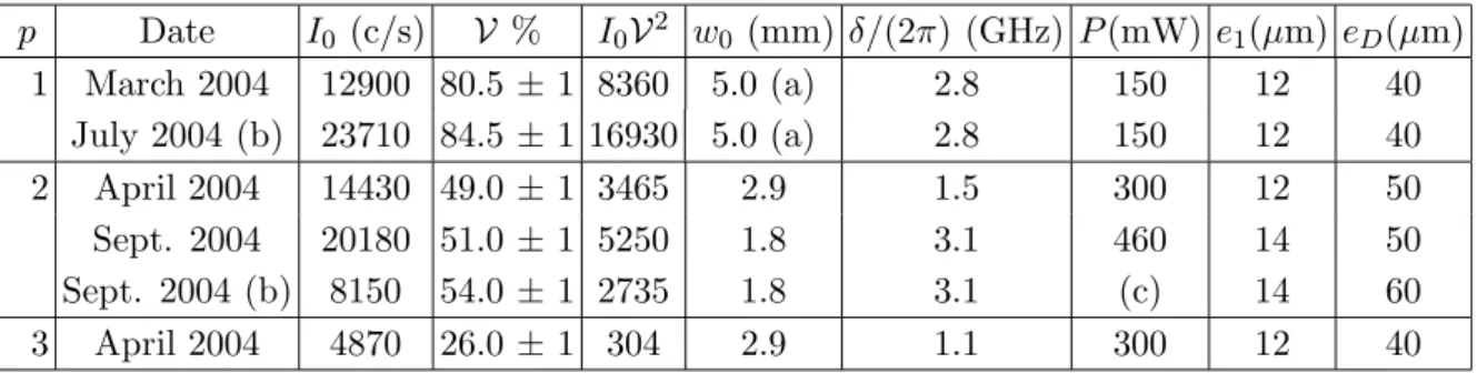
We have tilted mirrorM2 around the z-axis, by applying a voltage on the corresponding piezo-drive and we have recorded fringes and measured their visibility. We have converted the voltage applied on the piezo-drive into a rotation angle, using an external calibration and neglecting the piezo hysteresis. The measured visibility has been plotted as a function of the angle θz(M2) in figure (5). The visibility decreases rapidly, as expected, but it does not vanish where predicted by equation (12). We think that this is a kind of apodization effect: the predicted cancellations disappear if a smooth weight function of y replaces the 0 or 1 intensity function used to establish equation (12). D. Pritchard and co-workers have made a study very similar to the present one in [35].
B. Fringe visibility as a function of the mismatch between the distances between consecutive gratings
If the distances between consecutive gratings L12 and L23 are different, the symmetry of the Mach-Zehnder interferometer is broken and the visibility is reduced. This effect was studied by numerical simulation by Turchette and coworkers [48]. We have shown [40] that, if the diffraction due to the slit S1 is negligible, the visibility is given by:
V =V0
sinc pkGe0∆L 2L04
!
sinc pkGeD∆L 2L04
!
(13)
-300-250-200-150-100 -50 0 50 100 150 200 250 300 0.0
0.1 0.2 0.3 0.4 0.5 0.6 0.7 0.8 0.9 1.0
Z (M
2 ) ( rad) p = 1
V/V 0,1
Part a
-350-300-250-200-150-100 -50 0 50 100 150 200 250 300 0.0
0.1 0.2 0.3 0.4 0.5 0.6 0.7 0.8 0.9 1.0
V/V 0,2
Y (M
2 ) ( rad)
p = 2
FIG. 5: Fringe visibility measured as a function of the angle θz measuring rotation around the z-axis of mirror M2. The experiment has been done with the diffraction orders p = 1 (part a) and p= 2 (part b). The points are experimental and the curves are the best fits using equation (12). The agreement is excellent in the central region, where the visibility decreases twice as fast as when using p= 2 than when using p= 1, in agreement with equation (12).
where ∆L=L23−L12 (this formula was written in [40] for the diffraction orderp= 1 only).
To study this effect, we have moved the last mirror encountered by the laser beam on its way to the mirror M1 where it reflects and forms the first laser standing wave. This motion was done with a translation stage, so that the laser beam direction is conserved. For various positionsz of this translation stage, we have recorded atom interference signals and measured their fringe visibility V. The measurements have been fitted by equation (13), in
which we have replaced ∆L=z−zc, wherezc corresponds to the position which cancels the mismatch ∆L. The data points and their fit are plotted in figure 6 and the agreement is very good. We cannot explore a larger range ofz values because of the limited window diameter.
By a direct measurement on our machine, we have verified that the value of zc = 3.5 mm deduced from the fit corresponds well, with an uncertainty of ±0.5 mm, to the equality of the two distances L12 and L23.
-2 0 2 4 6 8 10 12 14 16 18 20 22
0.0 0.1 0.2 0.3 0.4 0.5 0.6 0.7 0.8 0.9 1.0
L = L 23
- L 12
(mm) V/V
0 (p)
FIG. 6: Fringe visibility as a function of the mismatch between the distances between consecutive gratings ∆L = L23−L12 = z−zc for first (triangles) and second (squares) diffraction orders.
The points are experimental and the curve is the best fit using our approximate formula (equation (13)), for a collimation slit width e1 = 14 µm. The fitted parameter are the maximum visibility V0(p) for each orderp and the positionzc corresponding to a vanishing distance mismatch.
C. Signal and fringe visibility as a function of slit widths
The widths of the collimation and detector slit can be adjusted by piezo actuators and they open symmetrically. We have varied these two slit widths and we have recorded the interference signals on which we have measured the fringe visibilityV and the mean intensity I0. These two quantities are plotted as a function of the detector slit width eD in figure 7 and as a function of the collimation slit width e1 in figure 8. This study is very useful to optimize the phase sensitivity of the interferometer.
If we consider first figure 7 representing the effects of the detector slit width eD, the signal intensity I0 increases linearly with eD up to eD ≈ 40 µm while the visibility V is roughly constant as long as eD < 60 µm: this first regime is what is expected when the detector slit collects only the signal corresponding to beam B1. Then for larger eD values, the intensity I0 increases more slowly and the visibility V decreases rapidly. Now, the detector slit is sufficiently opened to collect all the B1 beam and a part of the B2 beam.
If the interferometer was perfectly symmetrical, the B2 beam would carry the same flux as B1 beam with a complementary interference signal. The fact that the intensity increases with a slope reduced roughly by a factor 2 is in agreement with the fact that the slit opens
symmetrically and only one side of the slit is useful to transmit the B2 beam and the rapid decrease of the visibility is in good agreement with the fact that the two beams Bi carry complementary interference signals.
0 20 40 60 80 100 120 140 160
0 10 20 30 40 50 60 70 80 90 Signal (a.u.)
Detection slit width e D
( m)
FIG. 7: Fringe visibility V in % (dots), and mean signal intensity I0 in 103 counts/s (squares) as a function of the detector slit widtheD inµm while the collimation slit width is e1 = 12µm. The lines are simply drawn to guide the eye.
When the collimation slit width e1 is varied, the effects are slightly more complex. In particular, one should not forget that Bragg diffraction has a strong angular selectivity:
this selectivity makes that when the slit is widely opened, it admits in the interferometer atoms which have not the Bragg incidence and therefore these atoms have a low diffraction probability. These atoms will contribute to make the direct stray beam (the beam which is diffracted three times in the zeroth order) more intense. As long as the collimation slit width e1 is below 25µm, the intensity I0 increases with the slit width while the contrast is mostly constant. When 35< e1 <70µm, the intensity increases more rapidly, as a consequence of the broadening of the wings of the direct beam. As the direct beam carries no interference signal, the visibility decreases while the product I0V remains roughly constant. Finally, when e1 > 70 µm, the intensity saturates because the direct stray beam fully covers the detection slit and the visibility remains constant.
D. Fringe visibility as a function of an applied magnetic field gradient
An atomic Mach-Zehnder interferometer operating with paramagnetic atoms like lithium remains insensitive to a weak homogeneous magnetic field but the output signal is very sensitive to a magnetic field gradient, as explained below. This effect was studied by D.
Pritchard and co-workers [35, 51] and also by D. Giltner in his thesis [52].
In our experiment, the Earth magnetic field is not compensated. Moreover, the vacuum pipes are supported by a very heavy structure made of steel rails, but we have made efforts
0 10 20 30 40 50 60 70 80 0
10 20 30 40 50 60 70 80 90 100 110 120
Signal (a.u.)
Collimation slit width e
1 ( m)
FIG. 8: Fringe visibilityV in % (dots) and mean signal intensity I0 in 103 counts/s (squares)as a function of the collimation slit widthe1 inµm while the detection slit width iseD = 43µm. The lines are simply drawn to guide the eye.
to use very few magnetic parts inside the interferometer vacuum chamber, the only exception being small steel springs in the kinematic mounts of the three mirrors. The field along the atomic paths has been measured, it is very roughly homogeneous, reminiscent of the Earth field (of the order of 4×10⁻⁵ T) and an important point is that it never vanishes.
We assume that the field is weak, below 10−3 T, so that the hyperfine structure remains coupled: the eigenstates are the|F, MFisublevels and it is a good approximation to consider only first order Zeeman effect. As the field never vanishes, the adiabatic theorem can be applied and the projectionMF of the angular momentum remains constant on a quantization axis which follows the local direction of the field. The magnetic phases φ(F, MF) are given by:
φ(MF) = gFµBMF
¯ hv
Z
B(s)ds (14)
where gF is the hyperfine Land´e factor, B is the modulus of the magnetic field and the integral is carried along the atomic path. Neglecting the nuclear spin contribution to the atomic magnetic moment, for lithium 7Li, the nuclear spin is I = 3/2 and the hyperfine levels with F = 1 and 2 have opposite Land´e factors equal to gF =−1/2 for the F = 1 and gF = +1/2 for theF = 2.
The magnetic phases are quite large,φ(MF)/MF = 2×10³rad for a fieldB = 4×10⁻⁵ T.
Fortunately, these phases play no role in the absence of non-adiabatic transitions from one sublevel to another one. The interferometer signal is only sensitive to the phase difference for each sublevel between the two atomic paths. In the presence of a gradient of the magnetic field modulus B in the x direction, the interference pattern corresponding to the MF level suffers a phase shift ∆φ(F, MF) =ϕMF with ϕ given by:
ϕ = gFµB
¯ hv
Z dB(s)
dx ∆x(s)ds (15)
where ∆x(s) is the distance between the two atomic paths. Let us consider a magnetic dipole µparallel to thexaxis, located at a distance d from the atomic paths. We can get a closed form expression ofϕif we neglect the homogeneous background field and if we assume that ∆x(s) is almost constant over the region where the gradient of B is large, we get:
Z dB(s)
dx ds= µ0µ 2πd3
Z π/2
−π/2
h3 cos2θ+ 1i1/2cosθdθ (16) where the integral overθis equal to 3.42. One must not forget that the approximations made are not very good. With 7Li hyperfine level structure, in the absence of optical pumping, i.e. assuming the same population for the 8 sublevels, the interference visibility varies with ϕ in the following way:
V =V02 + 4 cosϕ+ 2 cos 2ϕ
8 (17)
With our approximations,ϕ is a linear function of the dipole moment or of the current if we use a coil. Moreover ϕ is proportional to v−2, where v is the atom velocity: a v−1 factor is obvious in equation (15) and the other factor is hidden in the quantity ∆x(s) proportional to the diffraction angle.
The velocity distribution of the lithium atoms induces a dispersion on ϕ which fur- ther induces a fringe visibility reduction. Assuming a Gaussian velocity distribution profile P(v)dv∝exp[−(v−u)2/α2], we deduce a phase distribution:
P(ϕ)dϕ∝exp[−(ϕ−ϕm)2/β2] (18) with the phase ϕm corresponding to the velocity u and β = 2ϕmα/u. This approximate formula is valid in the limit α ≪ u. After averaging over ϕ, the visibility V is then still given by equation (17), where cos(kϕ) (k is an integer) is replaced by its averagehcos(kϕ)>
over the distributionP(ϕ) simply given by:
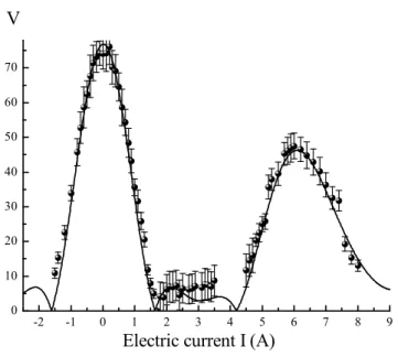
hcos(kϕ)>= cos(kϕm) exp[−k2β2/4] (19) We have done a first experiment with a coil outside the vacuum tank. The coil, with 350 turns and a mean turn area close to 50 cm2, is located at about 20 cm from the atomic paths. We have recorded interference fringes for different currents I, varying from 0 to 8 A by 0.1 A steps. We have measured the fringe visibility V, which is plotted as a function of the current I on figure 9. Because of the dispersion on ϕ due to the velocity distribution of the lithium atoms, the visibility observed at the peak of the revival is not as large as whenϕ = 0. As a consequence, the variation of the visibility with the applied field gradient contains an information on the velocity dispersion of the atoms contributing to the atomic interference signal. As Bragg diffraction is velocity selective, this velocity distribution may differ from the velocity distribution of the lithium beam measured at the entrance of the interferometer [37, 38]. The present arrangement with a large coil rather far from the atomic path is not very favorable for a precise analysis, because the applied field is perturbed by the magnetic parts of the setup, but with an improved arrangement, we hope to measure accurately the velocity distribution of the atoms contributing to the interference signal.
-2 -1 0 1 2 3 4 5 6 7 8 9 0
1 0 2 0 3 0 4 0 5 0 6 0 7 0
Electric current I (A) V
FIG. 9: Fringe visibility V as a function of the electric current I in the coil which creates a magnetic gradient over the atomic paths. The points are experimental while the full curve is the best fit using equations (17) and (19) with α/u = 0.111, a value rather close but lower than the one measured on our incident lithium beam α/u = 0.133, showing the selectivity of the Bragg diffraction process. The dashed curve is the curve predicted if the velocity was perfectly defined and equal tou (i.e. ifα= 0)
Recently, we have used a small coil under vacuum (3.5 turns of wire on a 3 cm diameter ring, with the coil center at a distance d = 7.5 mm from the atomic paths). In a first time, we have studied with care the region of near zero field gradient and we have observed an improved fringe visibility for a small current in the coil, thus proving that a small but non negligible magnetic field gradient is present in our apparatus. In such an experiment, we do not cancel everywhere the magnetic field gradient but we simply cancel the integral appearing in equation (15). In this experiment, the best observed visibility isV = 84.5±1.0
% for the diffraction order p= 1 and V = 54.0±1.0 % for the diffraction orderp = 2 and these results are presented in figure 4.
The effect of an electric field gradient exists also and it has been used recently [21] for the compensation of phase dispersion in an atom interferometer. The Stark effect is quadratic in electric field and, in a 2S1/2 state, it is, with an excellent approximation, independent of the F, MF sublevel as a consequence of the Wigner-Eckart theorem. The induced phase is the same for all the F, MF levels and this phase will play a role only if it is large, because of its dispersion with the atom velocity. A large phase will exist only if the electric field and its gradient are both large enough. The stray electric field normally encountered inside vacuum chambers are usually weak, below 1 V/cm, and we do not expect a large gradient, especially close to the metallic rail supporting the mirrors. The resulting loss of coherence due to the stray electric field should be fully negligible.