HAL Id: hal-03741298
https://hal.inria.fr/hal-03741298
Submitted on 1 Aug 2022
HAL
is a multi-disciplinary open access archive for the deposit and dissemination of sci- entific research documents, whether they are pub- lished or not. The documents may come from teaching and research institutions in France or abroad, or from public or private research centers.
L’archive ouverte pluridisciplinaire
HAL, estdestinée au dépôt et à la diffusion de documents scientifiques de niveau recherche, publiés ou non, émanant des établissements d’enseignement et de recherche français ou étrangers, des laboratoires publics ou privés.
A 2D image-based multiphysics model for lifetime evaluation and failure scenario analysis of self-healing
ceramic-matrix mini-composites under a tensile load
Giulia Bellezza, Guillaume Couégnat, Mario Ricchiuto, Gérard L. Vignoles
To cite this version:
Giulia Bellezza, Guillaume Couégnat, Mario Ricchiuto, Gérard L. Vignoles. A 2D image-based mul- tiphysics model for lifetime evaluation and failure scenario analysis of self-healing ceramic-matrix mini-composites under a tensile load. Journal of the European Ceramic Society, Elsevier, 2022,
�10.1016/j.jeurceramsoc.2022.07.037�. �hal-03741298�
A 2D image-based multiphysics model for lifetime evaluation and failure scenario analysis of self-healing Ceramic-Matrix mini-Composites under a tensile load
G. Bellezzaa,∗, G. Cou´egnatb, M. Ricchiutoa, G. L. Vignolesc
aTeam Cardamom - INRIA, Univ. Bordeaux, CNRS, Bordeaux INP, IMB, UMR 5251, 200 Avenue de la Vieille Tour, Talence cedex, 33405, France
bCNRS, Laboratoire des Composites ThermoStructuraux (LCTS), UMR 5801 CNRS, Univ. Bordeaux, CEA, Safran, 3, All´ee de La Bo´etie, Pessac, 33600, France
cLaboratoire des Composites ThermoStructuraux (LCTS), UMR 5801 CNRS, Univ. Bordeaux, CEA, Safran, 3, All´ee de La Bo´etie, Pessac, 33600, France
Abstract
We propose a multi-physics numerical model for a self-healing ceramic matrix mini-composite under tensile load.
Crack averaged PDEs are proposed for the transport of oxygen and of all the chemical species involved in the healing process and studied in the dimensionless form to perform the most appropriate discretization choices concerning time integration, and boundary conditions. Concerning the fibres’ degradation, a slow crack growth model explicitly depen- dent on the environmental parameters is calibrated using a particular exact solution and integrated numerically in the general case. The tow failure results from the statistical distribution of the fibres’ initial strength, the slow crack growth kinetics, and the load transfer following fibres breakage. The lifetime prediction capabilities of the model, as well as the effect of temperature, spatial variation of the statistical distribution of fibres strength, and applied load, are investigated highlighting the influence of the diffusion/reaction processes (healing) on the fibre breakage scenarios.
Keywords: ceramic-matrix composites, self-healing, slow crack growth, image-based modelling
1. Introduction
Structural stability, resistance to oxidising environments, together with specific thermal-chemical properties are es- sential characteristics for the engineering design of civil aircraft jet engine hot part components. The ability to withstand heavy mechanical loads, very high temperatures and severe chemical stress, makes Ceramic Matrix Composite (CMC) materials based on long SiC fibers reinforcements the perfect candidates for assuming this role in the aerospace sector [1, 2, 3]. Several reinforcement designs have been put forward, like layups of UD prepregs or 3D interlocking of woven bundles, with an elaborate three-dimensional topological network [4]. The requirement for stiffmaterials has favored the choice of refractory carbides for the matrix, which are more brittle than the fibers and are suceptible to undergo multiple cracking markedly before the final material failure [5]. Although the CMCs do not have the brittle behaviour of their components [6, 7], they exhibit cracks before being subjected to mechanical or thermal loads due to the fabri- cation process. Initially the crack affects the matrix, and then, under the action of a specific load, it propagates to some fibres causing damage or breakage [8]. The cracks allow the diffusion of oxygen, which can reach the fibres and cause their oxidation, with subsequent degradation of their mechanical properties. Hence, the need to minimise the oxygen diffusion in the material as much as possible to avoid its degradation and the consequent rapid failure [9]. Self-healing processes [10] are essential to pursue this goal, allowing CMCs to exhibit an extremely long lifetime [11, 12]. SH- CMCs (Self-Healing CMCs) contain layers of reactive matrix added to take advantage of the passive action of the oxide produced to seal the crack. As a result, oxygen diffusion is reduced [13], and the fibres are protected from excessive oxidation. In particular, SEM observations in [14, 15, 16, 17] have highlighted the conditions for healing as a function of temperature, stress and water vapour content. In particular, in [17] the observations of the fracture surface after static fatigue test have well illustrated the mechanisms of recession and healing for CMCs with alternating matrix layers of the typeS iC,BxCandS i-B-C. However, due to the long lifetime of these materials, conducting experimental campaigns is expensive and time-consuming, and numerical modelling is a particularly needed complementary tool. The difficulty in describing the behaviour of such materials is related to the resolution of a complex multi-physical problem repre- senting the space-time evolution of physico-chemical phenomena that occur such as the oxygen diffusion through the crack, the evolution of the chemical species produced and consumed during oxidation, and the degradation of the fibres.
Moreover, the statistical dispersion of the mechanical properties of ceramic fibres due to their brittle nature is another
∗Corresponding author
Email address:giulia.bellezza@inria.fr(G. Bellezza)
Preprint submitted to Journal of the European Ceramic Society July 19, 2022
aspect to consider. Although several works have dealt with complex models describing the failure mechanics of CMCs [18, 19, 20], the challenges mentioned above have led many authors to use many simplifying assumptions. In particular, numerous previous works describing the behaviour of the crack healing process rely on simplified 0D [12, 21, 22] or 1D [23] approximations, providing values of the oxygen concentration in strategic points of the material. This has the benefit of allowing to solve the problem with some analytical or semi-analytical technique, but some information about the complete process is lost. To mitigate this loss, the work [24] described the self-healing process in a crack, focusing on the description of the oxide spreading but requiring an onerous computational time. The work described in this paper aims at making the multi-dimensional multi-physics model as tractable as possible. As a final result, this has enabled the investigation of the evolution in time and the failure scenario of a self-healing ceramic matrix mini-composite [25]
in an oxidising environment under a static fatigue test based on a two-dimensional image-based model of a transverse crack [24]. To reach this objective, appropriate models for all the processes involved are proposed, and validated as much as possible.
The paper is structured as follows: in section §2.1 we discuss the section averaged approximation for the diffusive- reactive processes in the transverse crack. A study of the dimensionless form of the associated PDE is reported in sections §2.2.2 and §2.2.3. The analysis allows to fully understand the contribution of each term, and perform the most appropriate discretisation choices in terms of boundary conditions, and time integration. Then, in section §2.3 we describe a slow crack growth model inspired from the one proposed in [26]. This model is used to predict the fibres progressive degradation taking into account the environmental parameters, especially the oxygen concentration, considering its extreme variation through the crack. Finally, the tow failure depending on the statistical fibres initial strength, slow crack growth kinetics, and load sharing following fibres breakage is captured thanks to an approximate mechanical model presented in section §2.4. Section §3 is devoted to the numerical exploitation of the model. The effects of temperature, spatial variation of the statistical distribution of fibres strength and applied load are presented and discussed in terms of material behaviour and lifetime prediction.
2. Model set up
2.1. Modeling strategy
In this section, the strategy used for the evaluation of self-healing ceramic matrix mini-composite lifetime under static fatigue tests is illustrated. Defining a certain stressσapplied to the mini-composite, the subsequent deformation and opening of the crack is calculated. The oxygen diffusion inside the crack leads to the oxidation processes of fibres and reactive matrix layers. The latter is responsible for the local healing of the crack by the generated oxide. In particular, the simulation involves the resolution of the diffusion-oxidation system in a two-dimensional domain accounting for the average (along the crack width) spreading of the protective oxide. The oxygen that arrives at the fibres must first diffuse through the silica layer formed around the fibres and then oxidizes fibres. The defects growth on the surface of the fibres is calculated as a function of the oxygen flux at the latter. We chose to consider the worst-case scenario, i.e.
when the maximum oxygen concentration value corresponds to the largest defect on a fibre. The bundle failure time calculated is, thus, conservative. Moreover, the model considers the growth of the silica oxide layer around the fibers and the diffusion of oxygen through it. The variation of the fibre resistance distribution is calculated according to the size of the defect. When a defect reaches the critical size, i.e. whenσr=σf ib, the fibre breaks and the oxide is spreaded on the new domain. The redistribution of the load over the intact fibres and the subsequent reopening of the crack is calculated. Finally the failure time of the mini-composite is computed as the time at which the critical fibre breaks, causing the failure of the whole bundle.
2.2. Self-healing modeling 2.2.1. Model description
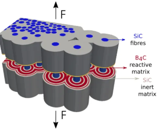
The crack network morphology in CMCs is well know [27]. Mainly two types of cracks in the material can be identified: inter-yarns cracks and intra-yarns cracks. The inter-yarns cracks occur first as the matrix in these areas is stiffer (and therefore more brittle) containing generally larger pores. These cracks develop orthogonally to the main load direction. As the material reaches the cracks network saturation, new cracks are formed in the matrix inside the yarns. Assuming a longitudinal load, the intra-yarns cracks are orthogonal to the longitudinal fibre bundles and parallel to the transverse fibre bundles. This last type of cracks is crucial because oxygen can diffuse through them, reaching the fibres and causing their subcritical cracking. For this reason, the present study focuses on the longitudinal bundle in which transverse crack appears, as it is shown in Fig. 1.
The composite is made up of Hi-Nicalon fibres surrounded by a pyrocarbon (pyC) interfacial coating and immersed in a multi-layered matrix [13, 28]. The matrix includes concentric layers ofS iCandB4Cdeposited via Chemical Vapour Infiltration (CVI). The sequence of these matrix layers gives the ”self-healing” character to the material. A complete description of the material morphology and the reaction kinetics are reported in [29]. Moreover, the introduction of reactive matrix layers protects the pyC interphase placed around the fibres from oxidation up to 1400°C. In fact, the
2
F
F
fibre
B4C SiC
SiC fibres
reactive B4C matrix
SiC inert matrix
Figure 1: Transversal crack in a longitudinal oriented fibres’ tow.
interphase plays the crucial role of deflecting the matrix cracks [7, 30, 31], conferring a certain pseudo-plasticity to the material despite being constituted by brittle components [6]. TheB4Clayers oxidation consumes part of the oxygen and the microcrack is sealed with anB2O3−S iO2liquid oxide above 450°C. This process creates a barrier to the diffusion of oxygen in the crack [13]. On the other hand, the reactivity of crystallizedS iCis low at intermediate temperatures (treated in this work), and therefore in the self-healing process, onlyB2O3oxide is considered. A full overview of the healing processes of this material is treated in [32]. The section averaged unsteady diffusion-reaction model underlying the current work was originally introduced in [24], and can be written as follows:
∂
∂t(hCO2)− ∇ ·(DO2h∇CO2)=−φRCO2kl
4.6 in Ω
CO2(t=0)=CO2ext on ∂Ωext
−DO2h∇CO2·nf =epkpCO2 on ∂Ωf
(1)
In eq. (1) the time-dependent section-averaged oxygen concentration in the crack is expressed as a balance between oxygen diffusion and the oxide formation through the crack. Consideringethe crack width, we assume the heighthg
as the space occupied by gas, while we denote byhlthe width occupied by the liquid oxide resulting from the matrix oxidation hm. The heighthis then given byh =e+hm−hl, when the plug has not totally fill the crack, andh = e otherwise. The oxygen diffusion flux in the crack is modelled by Fick’s law. In particular,DgO
2represents the (constant) diffusivity in of oxygen in the gaseous phase. The source term in eq. (1)a describes the oxidation of the B4Cmatrix layers through a reaction ratekldefined using the model proposed by Deal and Grove in [33]. This model assumes that the oxidation reaction occurs at the interface between the liquid oxide layer and the substrate material as is illustrated in Fig. 2. Thus, oxygen diffuses from the bulk of the ambient gas to the reactive matrix surface, then diffuses through a liquid layer to reach the oxide-matrix interface, and finally reacts with the substrate.
O2
B4C B2O3
(1)
(3) (2)
Figure 2: Oxidation/reaction model scheme for eq. 2a.
The model also assumes that each of these stages proceeds at a rate proportional to the oxidant’s concentration and in steady-state condition. Thus, the reaction rate constants have the following expressions:
3
1 kl = 1
kB2O3 + hg
DlO
2
1 kp = 1
kPyC +hp−ef
DO2
(2)
The diffusion and the reaction term in the system (1) are closely related because, once the oxide fills the crack, oxygen diffusion becomes extremely slow due to the different order of magnitude of the diffusion coefficient. A Dirichlet boundary condition (1)b is applied on the external domain considering that, at intermediate temperatures, the oxygen concentration in the pores is almost equal to that on the surface of the composite. At the beginning, when the plug is not effective yet, the oxygen concentration is related to the oxygen partial pressure byc0 = pO2/RT. The other boundary condition is of Robin-type and given by eq. (1)c. It establishes a correlation between the oxygen flux, reaching the pyC interphase and its oxidation. Once again, thekpreaction rate is defined (see eq. 2b) by the model proposed in [33]. Eqs.
1 and 2 are completed by the following system, which describes the evolution over time of the growth of the generated oxide layer and the parallel consumption of theB4Cmatrix layer and the pyrocarbon interphase:
∂hl
∂t =2VmB
2O3
4.6 φRklCO2
∂hm
∂t = VBm
4C
4.6 φRklCO2
∂hp
∂t = VPyCkpCO2
(3)
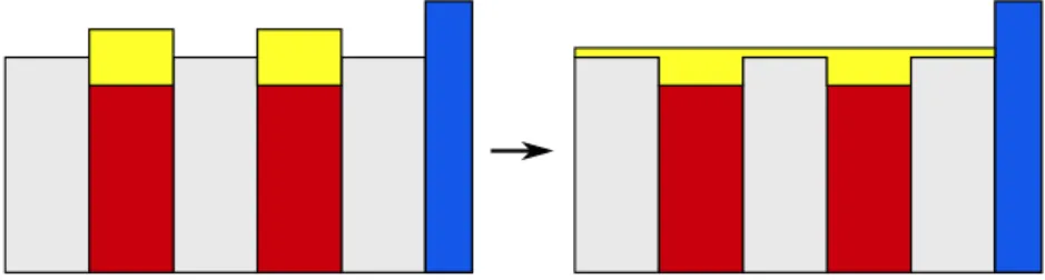
wherehlis the height of liquid oxide, whilehpandhmdenote the local consumed heights of PyC and matrix reactive respectively. In particular, in correspondence of the inert matrix phases note thathl+hg=e, the crack width. Otherwise, we havehl+hg =e+hm. The above system consists of ordinary linear and homogeneous differential equations of the first order, whose solution is obtained analytically by solving the corresponding problem according to [33]. In the present formulation, an instantaneous spreading of the produced oxide has been considered, as is illustrated in Fig.3;
it represents the unit cell of the fibres’ bundle in axial-symmetric crack assumption. This assumption is reasonable considering that at temperatures higher than 700°C it has been demonstrated that the contact angle of the B2O3liquid oxide at the interface with the matrix is zero[34].
Figure 3: A simplified scheme for an instantaneous spreading in a SH-CMC crack.
When the height of the crack is filled by oxide (plug formation), a system equivalent to (1) can be written for the concentration of oxygen in the liquid phase, of widthhl, and diffusivityDlO
2. 2.2.2. Dimensional analysis and optimal time step determination
Dimensional analysis is used to estimate the order of magnitude of the time-scales associated to each process. The final aim is to investigate the correct choice of the simulation time step to correctly track every aspect of the problem, i.e. the oxygen diffusion, the oxide production, the oxygen concentration variation over time, and simultaneously reducing the calculation time required. Indeed, the complete resolution of the system for a 2D finite element domain makes numerical integration computationally heavy. In the first 2D simulation attempt [24], the problem of the time step choice was considered and the decision fell on a compromise between the characteristic times of diffusion in the process, i.e. oxygen diffusion through a gaseous phase and then through a liquid one. This choice yields accuracy in the resolution of 5% compared to adopting as the time step the characteristic time of diffusion in the gas that is the finest one. The resulting model has however a computational cost making its use unfeasible for parametric studies of practical interest. In this work, we opted to carry out a proper dimensional study at the microscale level to quantify each phenomenon and formally adopt the appropriate choices. Considering a general variableG, we denote the corresponding non-dimensional variable byG∗given by:
4
G∗= G Gref
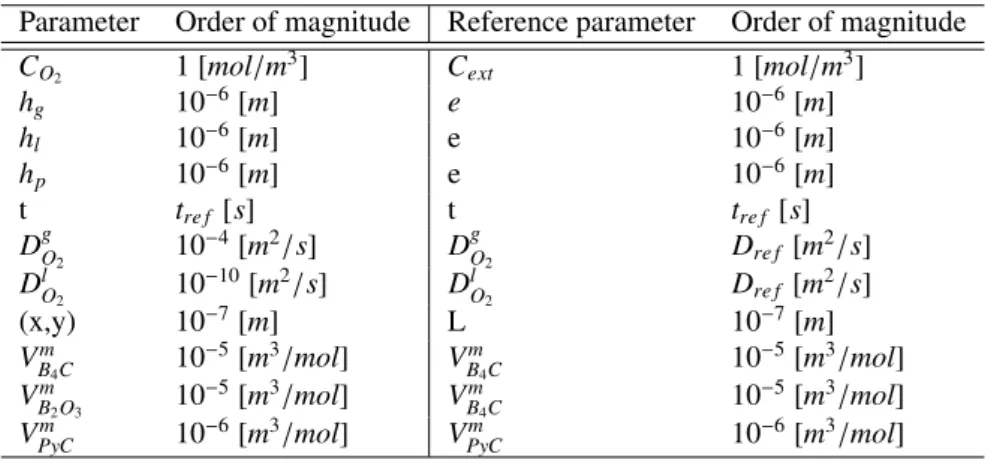
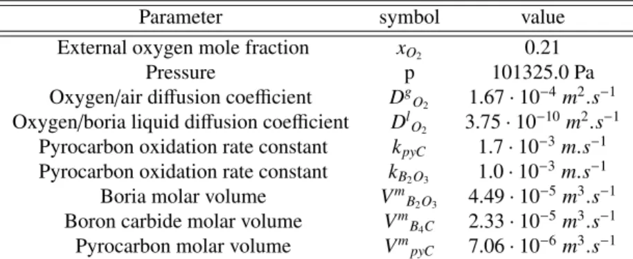
(4) The choice of the reference valueGrefis fundamental to obtain the correct scaling for the dimensionless model. In particular, this strategy allows the dimensionless groups formed in the equations to assume a physical meaning. The variables and parameters orders of magnitude involved in this study are shown in the Tab.1 together with the chosen reference values. The geometric parameters of the crack are representative of a realistic case [10]. The oxygen diffusion coefficients in air and in liquidB2O3are estimated considering the Chapman-Enskog relations [35] and the experimental data conducted at LCTS onBxCoxidation [36] respectively.
Table 1: Orders of magnitude and reference parameters involved in self-healing problem.
Parameter Order of magnitude Reference parameter Order of magnitude
CO2 1 [mol/m3] Cext 1 [mol/m3]
hg 10−6[m] e 10−6[m]
hl 10−6[m] e 10−6[m]
hp 10−6[m] e 10−6[m]
t tre f [s] t tre f [s]
DgO
2 10−4[m2/s] DgO
2 Dre f [m2/s]
DlO
2 10−10[m2/s] DlO
2 Dre f [m2/s]
(x,y) 10−7[m] L 10−7[m]
VmB
4C 10−5[m3/mol] VBm
4C 10−5[m3/mol]
VmB
2O3 10−5[m3/mol] VBm
4C 10−5[m3/mol]
VPyCm 10−6[m3/mol] VPyCm 10−6[m3/mol]
Let us consider the unsteady diffusion system (1). Dividing each term by the reference parameters linked to the unsteady term, the dimensionless equation assumes the following form:
∂∗
∂t∗(h∗CO2
∗)− Dre ftre f
L2
!
∇∗·(D∗O2h∗∇∗CO2
∗)=− Dltre f
e2
! φRCO∗
2k∗l
4.6 (5)
The study is performed by treating the two phases of the self-healing process separately. As stated above, depending on whether the diffusion problem is solved or not in the presence of protective oxide, the dimensional analysis must consider two different diffusion coefficientsDgO
2andDlO
2, which differ by several order of magnitude. The characteristic oxygen diffusion time in the gaseous and liquid medium are defined as follows:
tgas= L2 DgO
2
=10−10
tliquid = L2 DlO
2
=10−4
(6)
As a consequence of Eqs. 6, oxygen diffusion in air occurs much faster than in the oxide. By substituting the reference values given in Tab.1, we can rewrite the Eq. (5) for the two stages of the material healing process as
∂∗
∂t∗(h∗C∗O2)−
tre f ·1010
∇∗·(Dg∗O
2h∗∇∗C∗O2)=−
tre f ·104 φR
C∗O
2k∗l
4.6 , (7)
when the crack is not sealed by the oxide, and as
∂∗
∂t∗(h∗C∗O2)−
tre f ·104
∇∗·(Dl∗O2h∗∇∗C∗O2)=−
tre f ·104 φR
C∗O
2kl∗
4.6 , (8)
after the formation of the liquid plug. In both Eqs. (7) and (8) it is possible to highlight two dimensionless groups. The first represents the relative importance of the diffusion term with respect to the unsteady term. This group can also be interpreted as the ratio between two characteristic times: the reference timetre f, which is related to the variation of the oxygen concentration over time, and the characteristic time of the oxygen diffusion. The second group defines the time scale of the source term compared to the time scale of oxygen concentration variation in the crack. It is evident that in both phases of the problem, the two dimensionless numbers assume high values. This suggests that the transient plays a minor role in the process, which may as well be considered as stationary. In other words, we will choose the reference
5
time that does not explicitly depend on the characteristic times of diffusion and production. We can also highlight a different aspect related to geometrical considerations by dividing the Eq. (5) by the dimensional units of the production term:
e2 tre fDl
! ∂∗
∂t∗(h∗CO∗
2)− e2Dre f
L2Dl
!
∇∗·(D∗O
2h∗∇∗C∗O
2)=−φRC∗O
2k∗l
4.6 (9)
We can notice the appearance of the ratio of crack height and on crack length. In particular, the more the considered crack has a high aspect ratioL/e, the less important the diffusion, and the closer this ratio is to unity, the more important will be diffusion compared to production. As before, we can use the reference values of Tab.1, and differentiate the case without and with liquid plug. We obtain
tre f ·10−2 ∂∗
∂t∗(h∗CO2∗)− 108
∇∗·(Dg∗O
2h∗∇∗CO2∗)=−φRCO2∗kl∗
4.6 , (10)
in the gas, and
tre f ·10−2 ∂∗
∂t∗(h∗CO2
∗)− 102
∇∗·(Dl∗O2h∗∇∗CO2
∗)=−φRCO2∗kl∗
4.6 , (11)
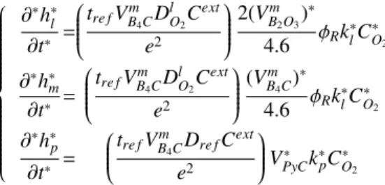
in the liquid oxide. It is evident that in the gas the reaction term does not significantly influence the diffusion of the oxide. Therefore, it is reasonable to split these two effects in the simulations. Let us now consider system (3) modelling the evolution of heights. Proceeding as before we obtain the following dimensionless system:
∂∗h∗l
∂t∗ =
tre fVBm
4CDlO
2Cext e2
2(VBm
2O3)∗ 4.6 φRkl∗CO∗
2
∂∗h∗m
∂t∗ =
tre fVBm
4CDlO
2Cext e2
(VBm
4C)∗ 4.6 φRkl∗CO∗
2
∂∗h∗p
∂t∗ =
tre fVBm
4CDre fCext e2
V∗PyCk∗pC∗O
2
(12)
First, we consider the two equations related to the variation in time of the oxide height and oxidation of the reactive matrix layers. We can see that both equations have the same dimensionless group that depends proportionally on the oxygen concentration, on the interfacial velocity constants, and, consequently, on the evolution of the oxide height (according to the model in [33]). By substituting the values listed in Tab.1 we obtain the following system:
∂∗h∗l
∂t∗ =
tre f ·10−32(VBm
2O3)∗ 4.6 φRk∗lC∗O
2
∂∗h∗m
∂t∗ =
tre f ·10−3(VmB
4C)∗ 4.6 φRk∗lC∗O
2
(13)
Since the diffusion/reaction process for the oxygen concentration can be assumed quasi-stationary, it is possible to adapt the time step of the complete self-healing problem to follow the evolution of the oxide height. In practice, an adaptive time step has been chosen in this sense. As a result, we have reduced the computational time required to simulate 1000 hours of the material lifetime to a few minutes on a laptop, making the model more interesting in practical applications compared to the one of [24].
The modelling of the interphase oxidation around the fibres has been then considered. Fig. 4 shows two boundary cases: the first case shows the interphase in direct contact with the oxide (Fig. 4a), in the second, the interphase oxidizes as a result of the diffusion of oxygen in the air (Fig. 4b). The actual configuration is, in fact, a function of the viscosity of the oxide and its ability to penetrate and fill the thin interfacial layer.
(a) (b)
Figure 4: Interphase oxidation models around the fibre.
6
Therefore, the dimensionless form of the equation related to pyC oxidation in Eqs. 12 can be written by referring to the above cases, respectively related to configuration (a) and (b):
∂∗hp∗
∂t∗ =
tre f ·103
VPyC∗kp∗CO2∗
∂∗hp∗
∂t∗ =
tre f ·10−3
VPyC∗kp∗
CO2
∗
(14)
The interphase oxidation rate in the two cases differs by the same amount as the difference in the characteristic diffusion times orders of magnitude related to the two phases considered as we expect.
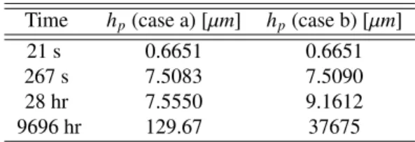
For a better insight, the one-dimensional model presented above has been studied. The simulation of self-healing has been carried out considering the two different boundary conditions applied to the fibre’s boundary. In Tab. 2 the respective consumed pyrocarbon height is reported for different simulation time.
Table 2: Pyrocarbon consumed height at T=700°C for different boundaries condition applied on the fibre at different times in one-dimensional SH problem.
Time hp(case a) [µm] hp(case b) [µm]
21 s 0.6651 0.6651
267 s 7.5083 7.5090
28 hr 7.5550 9.1612
9696 hr 129.67 37675
The consumed pyrocarbon interphase is almost the same in the first hours of simulation. The major difference lies in its final value, and, in particular, in case (b) the discrepancy is more than one order of magnitude after∼10000 hours.
This can be explained by the fact that at that time, the oxygen, which was previously consumed by the reactive matrices, reaches the fibre’s boundary and then spreads into the gas more rapidly than in case (a).
2.2.3. Boundary conditions and their influence on the model
To understand the influence of this choice on the system evolution, the variational formulation of the global problem in the dimensionless form has been studied. Denoting byνa generic test function the variational formulation reads:
Z Z
Ω
ν∂t(hC)dΩ +Z Z
Ω
Dh∇ν· ∇CdΩ− Z
∂Ωf
νFndγ− Z
∂Ωext
νFndγ+Z Z
Ω
νφRklC
4.6 dΩ =0 (15)
The normal flux of oxygen at the fibres’ boundary is defined by the expression below (cf Eq. (1)c):
Fn=epkpCO2 on ∂Ωf (16)
At the external boundary, a weak approximation of the Dirichlet condition is obtained by computing the oxygen normal flux through a layer of thickness equal toδis proportional to the difference between the oxygen concentration inside and outside the boundary (forδtending to zero this means applying a Dirichlet conditionCO2 =COext
2, see also [37] and references therein):
Fn= eD
δ (CO2−COext2) on ∂Ωext (17)
By inserting Eq. (16) and Eq. (17) into Eq. (15), the variational formulation can be rewritten with the appropriate boundary condition:
Z Z
Ω
ν∂t(hC)dΩ +Z Z
Ω
Dh∇ν· ∇CdΩ− Z
∂Ωf
νepkpCO2dγ− Z
∂Ωext
νeD
δ (CO2−CextO
2)dγ+Z Z
Ω
νφRklC
4.6 dΩ =0 (18)
By resizing each term considering the reference values in the Tab.1 and reporting the respective order of magnitude, we obtain:
7
Z Z
Ω
hre fCre f
tre f
!
ν∂t(hC)dΩ +Z Z
Ω
Dre fhre fCre f
L2re f
!
Dh∇ν· ∇CdΩ− Z
∂Ωf
(Dre fCre f)νepkpCO2dγ−
− Z
∂Ωext
Dghre fCre f
δre f
! νeD
δ (CO2−CextO
2)dγ+Z Z
Ω
Dlhre fCre f
hre f
! νφRklC
4.6 dΩ =0 (19)
Dividing through by the transient term results in the following formulation for the gas-diffusion stage Z Z
Ω
ν∂t(hC)dΩ +(1010·tre f) Z Z
Ω
Dh∇ν· ∇CdΩ−(102·tre f) Z
∂Ωf
νepkpCO2dγ
− 10−2 δre f ·tre f
! Z
∂Ωext
νeD
δ (CO2−CextO
2)dγ+(103·tre f) Z Z
Ω
νφRklC
4.6 dΩ =0.
(20)
For the oxide-diffusion stage we have Z Z
Ω
ν∂t(hC)dΩ +(104·tre f) Z Z
Ω
Dh∇ν· ∇CdΩ−(10−4·tre f) Z
∂Ωf
νepkpCO2dγ
− 10−4 δre f
·tre f
! Z
∂Ωext
νeD
δ (CO2−CextO2)dγ+(103·tre f) Z Z
Ω
νφRklC 4.6 dΩ =0
(21)
We can clearly see that for both stages the importance of the external boundary condition is very limited compared to the other phenomena, and in particular compared to the boundary condition on the fibres. Therefore, it is expected that a change in the parameters’ values in boundary condition does not substantially affect the global self-healing process behaviour. In this work we assumed as boundary conditions on the fibres the situation shown in Fig 4a, i.e. the case in which the oxide is in direct contact with the pyC interphase, as the temperatures considered are higher than 700°C.
2.3. Sub-critical crack growth modeling 2.3.1. Model description
Unfortunately, despite of the introduction of reactive matrices, and of the resulting crack healing, the fibres’ protection from the environment is not complete. Consequently, the degradation mechanisms of the fibres is the most critical factor in the operational life of the material [12, 38]. In particular, fibres are attacked by an aggressive environment, such as air, and are damaged through an oxidation process [39, 40]. This phenomenon is called slow crack growth and has experimental and fractographical bases [41]. Moreover, the formation of a uniform layer of silica (silicon dioxide) on the surface of the fibres and a thin layer of oxide between 650°C and 730°C is observed. The tests show that the growth of the silica layer on the surface of the fibres is not responsible for the fracture. It has also been proven that the growth of the silica layer and the diffusion of oxygen under load are increased. The diffusion of oxygen controls the oxidation of the fibres through the oxide layer. This phenomenon is also called static fatigue. Many existing works use a Paris law’ for its description [40, 38, 42, 43] that correlates crack velocity with the crack stress intensity factorKcomputed under the assumption of elastic behaviour:
da
dt =C·(∆K)n (22)
whereais the defect size,Candnrepresent the material coefficients dependent on environmental effects, stress ratio and specimen size. The stress intensity factor K depends on the sample geometry, the crack position, and the load applied to the material. The dependence on the environment is ensured via the coefficientsC andnobtained experimentally.
This indirect dependence on the external condition, as e.g. variable concentration as it is the case within the crack, is the main limitation of this law. For this reason, we have followed the approach formulated in [26]. In this approach, the two stages that constitute the mechanism of damage ofS iCfibres in an oxidizing medium are highlighted: the first stage is controlled by the reactions, and the crack tip is directly damaged. The second stage involves first the diffusion of oxygen through the S iO2 oxide layer formed on the fibre and then the reaction on the fibre’s surface. For this reason, this phase is primarily controlled by a diffusion mechanism. In the approach mentioned above, the environment modifies the damage zone only at the cracks tip, and it does not depend explicitly on temperature but depends only on
8
the total oxygen flux reacting at the crack’s tip (which, in turn, depends on the temperature and the oxygen pressure).
Consequently, the model is valid for any temperature or oxygen pressure, which can be time functions. The growth of surface defects is assumed to be a one-dimensional problem in which a scalar parameter describes the size of a defect.
Thus, the Stress Intensity Factor (SIF), denoted withK, is approximately uniform along the crack tip and considering that the impact of the environmental conditions on the elasticity coefficients is limited. In ceramics fracture starts in general from small flaws, which are discontinuities in the micro-structure and which, for simplicity, can be assumed to be small cracks distributed in the surface or volume. Strength then depends on the size of the largest (or critical) defect in a specimen, and it varies from component to component. Due to this reason, design with ceramics has to be approached statistically. In the Weibull theory, the strength of a fibre of length L, denoted withσR, follows the cumulative density function:
P(σR< σ)=1−exp
−L L0
σ σ0
mσ
(23) whereL0,mσandσ0are the classical Weibull coefficients. In particular, the Weibull modulusmσdescribes the scatter of the strength data, the characteristic strengthσ0 is the stress at which, for specimens of volumeV =V0, the failure probability is equal to 1=exp(=1)=63%. Thus, the SIF induced by a surface defect of size a in a fibre subjected to a stressσcan be calculated considering the Griffith theory managed by Irwin for brittle materials:
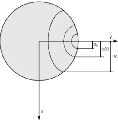
K=σ·Yp
a(t) (24)
whereY is the shape coefficient associated with the crack assumed to be constant throughout the propagation. It is considered thatY = √
2πfor penny-shaped crack with small extension as compared to the system size. The largest surface defect (whose initial size is denoted witha0) is responsible for fibre failure in quasi-static tensile testing as well as in static fatigue. During quasi-static loading, the SIF reaches the Critical Stress Intensity Factor (CSIF), denoted with Kc, at the largest surface defect when the applied stress reaches the strength of the fibres, denoted asσR. Therefore, the initial size of the largest surface defect is obtained, for any given strength, by:
a0= Kc
σRY 2
(25) Similarly, if the fibre is stressed atσ < σR, there exists a critical defect sizeac>a0for which the SIF reaches the CSIF:
ac=Kc
σY 2
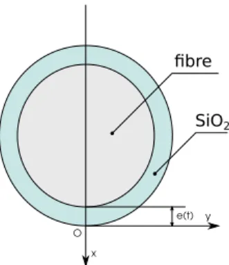
(26) In Fig.5 is represented the adopted scheme for the defect growth in the fibre and in Fig.6 the silica growth represen- tation under unidirectional problem assumption.
ac a0
a(t)
x
y
Figure 5: Scheme for the SCG in fibres.
By defining the correlation between CSIF and a sub-critical stress intensity factor (SCSIF), which depends on temper- ature and reaction rate, and by solving the relative diffusion-reaction problem at the crack tip of the fibres, the following differential problem is obtained whose solution is the fibre break time denoted here astR[26]:
9
x
e(t) y O
fibre SiO2
Figure 6: Unidirectional problem illustration of silica layer growth for fibres.
˙
a(t)= 1
(λKc)1/n · k·c0
(1+k·e(t)/D)·σ1/nY1/np a(t)1/n
∂e
∂t =−ρ
M ·(1+k·ck·e(t)/D)0(t) e(t=0)=0
a(t=0)=a0(σR) a(t=tR)=ac(σ)
(27)
The two differential equations respectively describe the evolution of the defect size and the silica layer over time. The diffusion coefficient of oxygen in silica is assumed to be Arrhenius-dependent in temperature, as well as the reaction rate coefficient:
DO2/S iO2=D0·exp
−Eda
RT
; k=k0·exp
−Eka
RT
; (28)
whereEdaandEkaare the activation energies. c0represents the oxygen concentration at the crack’s tip,σis the load applied on the fibre, andρandMare respectively the density and the mass of silica. In this model (Eqs. (27)), there are two parameters for calibration,λandk. In [26], these parameters were calibrated using the experimental data shown in [38] regarding Hi-Nicalon fibres. Moreover, in [26] only constant loading and environmental conditions have been investigated.
2.3.2. Calibration of the model
The sub-critical crack model described has been coded, revealing some inconsistency concerning the treatment of dimensions in the originals publication. An incongruity of the unit of measure adopted in the original paper has led to an inexact calibration of the parameters involved. For this reason, we have re-calibrated the model, and we report here explicitly the steps of this calibration. First of all, the analytical solution of the problem has been derived in case of constant oxygen concentration as in the experimental cases with available data, and as in the work [26].
tR = M 2Dρc0
2n
2n−1(a
2n−1
c2n −a
2n−1 2n
0 ) ρ
M(λKσY
c)1/n +D
k 2
− D
k 2
(29) withc0 = pRTO2. The analytical solution has been then used to re-parametrize the model with the experimental data of [38] as follows:
• It has been chosen to calibrate the problem considering only the value ofλto avoid the dimensional inconsistency found in [26]:
λ=1.12mol m3
n
(30)
• The value ofk0remains unchanged. The reaction coefficient then changes automatically with temperature with an Arrhenius-dependence.
The experimental reference data provided in [38] and used in [26] to validate the model were referred to the lifetime of Hi-Nicalon fibres in the case of constant loading and environmental condition. The same experimental data have been
10
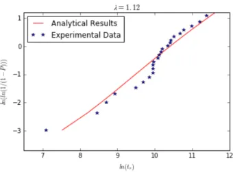
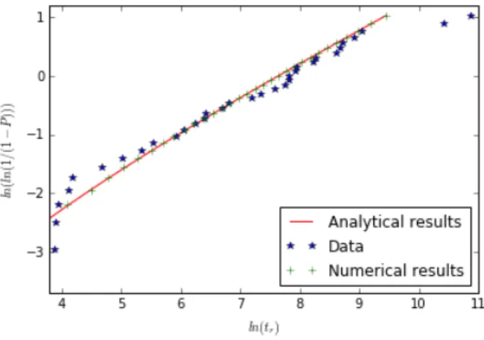
used to calibrate the analytical formula obtained, as is shown in Fig.7.
Figure 7: Cumulative lifetime probability distributions of the fibers: analytical modelT=773 Kσ=1500 MPa
The different calibration causes a slightly shifted curve with respect to the one obtained in the original work. Finally in Fig. 8 the perfect agreement between the results calculated with the newly-calibrated model analytically and numerically is shown.
Figure 8: Cumulative lifetime probability distributions of the fibers: newly-calibrated analytical vs. numerical modelT=1073 Kσ=1100 MPa
2.4. Failure mechanics
It is known that CMCs have two different damage evolution regimes. The first generally occurs for low-stress values and shows a growth of defects present in the matrix that evolve into a crack in the material. Due to the presence of debonding between matrix and fibres, the crack does not penetrate the fibres. This phase is mainly controlled by the evolution of the defects inside the matrix. The second phase is called tough behaviour and occurs for high loads. During this phase, the tow failure is entirely controlled by the evolution of the defects present in the fibres. However, it has been demonstrated in [44] and [45] that failure stress is controlled by the characteristic fibre strength relevant in the saturated-matrix crack regime. The evolutions of stresses along the fibres and the matrix for an axially loaded fibre bundle are shown in [46]. A simplified version of this description is proposed in this work. It is considered that, in the debonding zone, the load is constant and maximum, i.e. there is no load transfer between matrix and fibre, which is a conservative assumption. Considering a tensile loadFapplied on a mini-composite and using the isostress assumption, each fibre carries a loadFiproportional to its cross-section areaAi:
Fi=F Ai Pnfibres
i=1 Ai
(31) and therefore its stress is given by:
σf = Fi
Ai = F Pnfibres
i=1 Ai
(32) 11
Using these assumptions, the fibres stress only depends on the surface of the actual fibres carrying the load, which we refer to asnf ibres. For a load-controlled test, such as a static fatigue test, each broken fibre will increase the load carried by the remaining fibres. In global load-sharing assumptions, the stress acting on the surviving fibresσ, the average strainand the opening of the crackecare calculated as follows:
σ= F0
(n0fibres−nbroken)Sf
(33)
= F0
(n0fibres−nbroken)SfEf
(34)
ec=ld
F0
(n0fibres−nbroken)SfEf (35)
wheren0f ibresrepresents the initial number of fibres.
3. Model results and discussion
3.1. Numerical discretization and implementation
The numerical resolution of system (1) is achieved using a developed finite element scheme which consists of dis- cretization over a basis functions set of the proposed variational formulation in (18) [47]. The algebraic system obtained is then solved considering the basis function parameters as the variable values at the integration points of the elements.
In particular, triangular P1 elements are used in this study. For the discretization over time a first-order implicit Euler scheme is used. The solution for each time step is then coupled with the resulting calculation of the heights evolution (3) system which can be obtained analytically as demonstrated in [33].
3.2. Failure time modelling and model parametrization
We have investigated the predictive capabilities of the model proposed on the cracked-yarn configuration shown on Fig.9.
The physical/chemical parameters mentioned above and considered in this work are listed in Tab. 3, while the parameters related to the mechanical computation are listed in Tab. 4. Concerning the parameters used to model the sub-critical propagation in fibres, we used the same parameters as in [26] with the exception of the re-calibrated parameterλ.
Table 3: Physico-chemical parameters.
Parameter symbol value
External oxygen mole fraction xO2 0.21
Pressure p 101325.0 Pa
Oxygen/air diffusion coefficient DgO2 1.67·10−4m2.s−1 Oxygen/boria liquid diffusion coefficient DlO2 3.75·10−10m2.s−1 Pyrocarbon oxidation rate constant kpyC 1.7·10−3m.s−1 Pyrocarbon oxidation rate constant kB2O3 1.0·10−3m.s−1 Boria molar volume VmB2O3 4.49·10−5m3.s−1 Boron carbide molar volume VmB4C 2.33·10−5m3.s−1 Pyrocarbon molar volume VmpyC 7.06·10−6m3.s−1
Table 4: Geometrical and mechanical parameters.
Parameter symbol value
Hi-Nicalon fibres elastic modulus Ef 280·109 Pa
Debonded length ld 250µm
Area fibres tot. Af 0.0077mm2 Minicomposite section Atow 0.0205mm2
We have first performed a purely mechanical simulation, i.e. without generating the protective plug. In particular, the simulation was carried out for T=973 K and applied stressσ=1 GPa and a Weibull distribution of fibre strength values. Fig.10a shows the failures times of each fibre as a function of the assigned σR and fibre-to-tow outer edge
12
distance. As is evident, the sequence of fibre failure is a function only of the initial failure probability distribution and therefore follows the Weibull law introduced above. There is no correlation between the breaking times and the position of the fibres inside the yarn.
Figure 9: Tow 1 configuration.
Subsequently, the same simulation was repeated introducing the self-healing action. In Fig.10b, identical environ- mental and mechanical conditions have been considered. Moreover, the values of the initial distributions ofσRof the fibres are the same as those chosen in Fig.10a. The scenario of bundle failure shows that both the sequence and the times of fibres breakage events are dependent on the fibre position in the yarn. This effect is clearly due to the level of oxygen concentration reaching the fibres. As stated above, the oxide allows to slows down oxygen diffusion from the outside towards the tow.
10-2 10-1 100 101
Failure Time (hr) 1.0
1.5 2.0 2.5 3.0 3.5
R(GPa)
= 1000 MPa, T = 973 K
40 50 60 70 80 90 100 110
x (µm)
(a)
10-1 100 101 102 103 104
Failure Time (hr) 1.0
1.5 2.0 2.5 3.0 3.5
R(GPa)
= 1000 MPa, T = 973 K
40 50 60 70 80 90 100 110
x (µm)
(b)
Figure 10: Fibres’ failure history in function of their initial strength and distance from the outer boundary atT=973 K andσ=1 GPa without (10a) and with oxide (10b).
To demonstrate this concept, Fig. 11 shows the maximum concentration of oxygen on the fibres in the case of fibres closer to the outer domain, which are surrounded by only one sequence of matrix layers, in the case of fibres in the second row, and in the case of fibres placed more internally in the tow. In all cases the oxygen concentration is constant until the crack has been filled by the oxide and then has a rapid drop, which is in agreement with results obtained by other models in literature ([21, 12]). Then, the oxygen starts over diffusing through the crack at a slower rate and first reaches the fibres closest to the outer edge.
Thanks to the action of the oxide produced, it can be observed that the tow lifetime is longer than the one calculated in the relative non-oxide case reported with the straight line. To illustrate the concept in more detail, Fig. 12 illustrates a spatial representation showing the position of the fibres that break during the life of the material under the imposed conditions.
In particular, the strong dependence of fibres’ life time on their position in the yarn in the case of complete self-healing and on their initial strength in the case of non-healing is evident in Fig. 13.
The final interphase consumption for each fibre as a function of oxygen concentration is also shown in Fig. 14. Fibres with the highest oxygen concentration are the ones around which the pyC interphase is most consumed. The data points can be well fitted by a power law with exponent 0.6103, which is higher than the naively expected 1/2 exponent arising
13
10 4 10 3 102 101 100 101 102 103 Time (hr)
0.0 0.5 1.0 1.5 2.0 2.5
Oxygen concentration (mol.m3) external fibres middle fibres internal fibres
Figure 11: Oxygen concentration at the surface of fibres vs. time forσ=1 GPa andT=973 K.
42 35 29 23 17 12 6 0
days
Figure 12: Fibres’ failure history representation of simulation 10b in the 2D crack’s domain.
10 2 10 1 100 101 102 103 104 105
Failure Time (hr) 20
40 60 80 100 120 140 160
x (µm)
Applied Stress = 1000 MPa, T = 973 K without oxide with oxide
Figure 13: Fibres’ failure time w.r.t. distance from the outer domain considering the oxide 10b and non-oxide 10a simulation atT=973 K andσ=1 GPa.
from a classical parabolic oxidation model.
Moreover, Fig. 15 provides a more accurate representation of the failure scenario of the first six fibres of the simu- lation shown in Fig. 10b. Each fibre starts with an initial resistance value which continuously decreases as the size of its critical defect increases. The rate of this decrease is dependent on the oxygen concentration reaching the fibre. The more the fibre is subjected to a high oxygen concentration, the faster the propagation of its critical defect. WhenσRof the fibre is equal to the stress, it fails. In this case, the first fibre that breaks is the one with the lowest initialσR. Already for the second fibre that breaks the situation is different. This fibre is not initially the second with the lowest resistance, but it is the third. It breaks before the one with the lowest initial resistance because it has a higher defect propagation rate since it sees a higher oxygen concentration value. Obviously, for each fibre that breaks, the line representing the
14
0.00 0.25 0.50 0.75 1.00 1.25 1.50 1.75 2.00 Oxygen concentration (mol.m3)
0.000 0.025 0.050 0.075 0.100 0.125 0.150 0.175
Consumed pyC length (mm)
data points hpyC= 0.1102 CO0.61032
Figure 14: Ultimate pyC interphase consumed w.r.t. oxygen concentration at fibres’ tip forσ=1 GPa andT=973 K.
stress acting on the fibres has a jump due to global load sharing. As soon as a fibre breaks, the oxide instantly fills up the newly created space, allowing oxygen to diffuse there.
0 20 40 60 80 100 120 140
Time (hr) 0.0
0.1 0.2 0.3 0.4 0.5
Fibers oxygen concentration (mol.m−3)
oxygen concentration at fiber fiber strength
fiber stress
0.0 0.5 1.0 1.5 2.0 2.5 3.0 3.5 4.0
Fiber strength (GPa)
Figure 15: Time evolution of fibres’ oxygen concentration, strength and applied stress for 10b.
In Fig. 16, the evolution of the number of broken fibres over time was analysed for both cases (healing/non-healing).
The effect of the oxide is to slow down the growth of the critical defect in the fibres and protect them for a longer time. This result is translated in different breaking times for the fibres, especially in the final part of the bundle life, when a certain number of fibres are already broken. On the other hand, in the case where there is no plug, the speed of propagation of the defects in the fibres is higher, and therefore there are more fibres that reach breakage in short times.
10 20 30 40 50 60
Failure Time (hr) 0
5 10 15 20 25 30 35
Number of broken fibres
without oxide with oxide
0 200 400Failure Time (min)600 800 1000
Figure 16: Evolution in time of the number of broken fibres for the oxide 10b and non-oxide 10a simulation cases.
We have then investigated the effect of the applied stress on the mini composite failure time. Fig. 17a shows the 15