HAL Id: hal-00746632
https://hal.archives-ouvertes.fr/hal-00746632
Submitted on 29 Oct 2012
HAL is a multi-disciplinary open access archive for the deposit and dissemination of sci- entific research documents, whether they are pub- lished or not. The documents may come from teaching and research institutions in France or abroad, or from public or private research centers.
L’archive ouverte pluridisciplinaire HAL, est destinée au dépôt et à la diffusion de documents scientifiques de niveau recherche, publiés ou non, émanant des établissements d’enseignement et de recherche français ou étrangers, des laboratoires publics ou privés.
Numerical-experimental comparison in the simulation of rotor/stator interaction through blade-tip/abradable
coating contact
Alain Batailly, Mathias Legrand, Antoine Millecamps, François Garcin
To cite this version:
Alain Batailly, Mathias Legrand, Antoine Millecamps, François Garcin. Numerical-experimental com- parison in the simulation of rotor/stator interaction through blade-tip/abradable coating contact.
Journal of Engineering for Gas Turbines and Power, American Society of Mechanical Engineers, 2012, 134 (8), �10.1115/1.4006446�. �hal-00746632�
Numerical-experimental comparison in the simulation of rotor/stator interaction through blade-tip/abradable coating contact
Alain Batailly
Structural Dynamics and Vibration Laboratory, Department of Mechanical Engineering, McGill University, 817 Sherbrooke St West, Montréal, Québec H3A 2K6, Canada
e-mail: alain.batailly@mcgill.ca Mathias Legrand
Structural Dynamics and Vibration Laboratory, Department of Mechanical Engineering, McGill University, 817 Sherbrooke St West, Montréal, Québec H3A 2K6, Canada
Antoine Millecamps
Snecma, site de Villaroche, 77550 Moissy-Cramayel, France François Garcin
Snecma, site de Villaroche, 77550 Moissy-Cramayel, France
Abstract
Higher aircraft energy efficiency may be achieved by minimizing the clearance be- tween the rotating blade tips and respective surrounding casing. A common technical solution consists in the implementation of an abradable liner which improves both the operational safety and the efficiency of modern turbomachines. However, unex- pected abradable wear removal mechanisms were recently observed in experimental set-ups as well as during maintenance procedures. Based on a numerical strategy pre- viously developed, the present study introduces a numerical-experimental compari- son of such occurrence.
Attention is first paid to the review and analysis of existing experimental results.
Good agreement with numerical predictions is then illustrated in terms of critical stress levels within the blade as well as final wear profiles of the abradable liner. Numerical results suggest an alteration of the abradable mechanical properties in order to explain the outbreak of a divergent interaction. New blade designs are also explored in this re- spect and it is found that the interaction phenomenon is highly sensitive to (1) the blade geometry, (2) the abradable material properties and (3) the distortion of the cas- ing.
Nomenclature
Φ transformation matrix K stiffness matrix u displacement vector
σΩ stress in the middle of the blade in the radial direction due to centrifugal effects σY yield strength
σvm von Mises stress
σrr stress in the radial direction E Young’s modulus
f frequency
f1 first eigenfrequency of the blade fΩ rotational frequency
fΩ,int interaction rotational frequency K plastic modulus
TΩ,int interaction rotational period
1 Introduction
Rotor/stator interaction in compressor and turbine stages of turbomachines[1]commonly refers to unrelated phenomena arising in fluid and structural dynamics. Aerodynamicists essentially have interest in severe pressure fluctuations as well as potential flow and wake interaction[2,3]generated in modern designs involving a reduced number of blades to- gether with minimal axial spacing. Subsequent investigations of three-dimensional, turbu- lent and inherently unsteady flows in multi-stage compressors introduce significant com- putational challenges[4]. From a structural standpoint which is of interest in the present work, experiments conducted in vacuum environments[5]showed that rotor/stator inter- actions through unilateral contact and dry friction may lead to unacceptable damages to the rotating and static mechanical components[6,7]. Three distinct phenomena have been identified:
1. Modal interaction (also termed traveling wave speed coincidence)[8]is a geometric matching between the vibration modes of the interacting structures[9,10]. Ampli- tudes of vibration are driven by direct contact conditions.
2. Rubbing is characterized by significant wear on the casing or/and on the blade-tip[11, 12]. It involves a single blade and may be localized on the casing.
3. Whirl and whip[13,14]are motions arising due to precessional orbits in the rotating system.
The distinction between these phenomena is arduous since they may be combined. They are intimately associated with modern designs aiming at maximizing the energy efficiency of turbomachines. This is achieved by reducing parasitic leakage flows between the rotat- ing and stationary surrounding components through the closure of operating clearances.
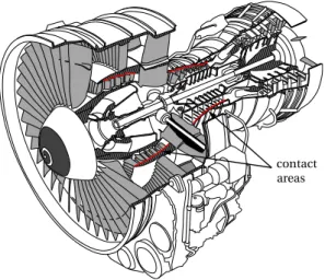
Possibly violent and destructive unilateral contact events may occur in sensitive areas de- picted in Fig.1. It is here assumed that both modal interaction and rubbing are involved in the scrutinised experimental test-run data. Whirl/whip phenomena are not considered be- cause the disk dynamics and shaft vibration were shown to be negligible during the exper- iment. In this context, the implementation of abradable coatings has been recognized as
contact areas
Figure 1: Cut-view of an aircraft engine with sensitive contact areas ( ).
a robust solution advantageously combining the adjustment of operating clearances with the reduction of non-repairable damage. Nevertheless, manufacturers recently observed
unexpected wear, missing blade parts and blade cracks[5,15]after experimental run tests designed to induce slight blade incursion into the abradable coating.
A suitable modeling of abradable materials together with a proper characterization of the main parameters will shed light on these phenomena of interaction for which in-depth knowledge is missing. If the experimental static characterization of this material[16,17]
is known, the dynamic characterization is still being investigated[18]. For instance, the fi- nite element method combined with an optimization procedure is employed in[19]for the simulation of the HR15Y hardness test on abradable material. It was shown that a bilinear plastic law could accurately represent the mechanical behavior of abradable material. Re- cent exploratory numerical tools could also approximate the behaviour of abradable coat- ing through the application of one-dimensional plastic elements[20]. This strategy proved to be promising with consistent prediction of critical rotational frequencies and wear pro- files of the abradable liners[21]. The present work intends to bring a new insight through a meticulous a posteriori comparison between accessible experimental evidence of the in- teraction scenario and numerical outcome of the aforementioned developed predicting tool[20].
The first section describes the industrial experiment and respective results provided in[5]. Then, the respective modeling and dedicated numerical strategy proposed in[20]
are summarized. The heart of this work is detailed in section 3: it compares experimental observations to numerical results. The last section is devoted to exploratory considerations:
attention is paid to the outbreak of the interaction phenomenon and its sensitivity to new blade geometries.
Note — In sections2,3and4of this paper, experimental data[5]is plotted in red while numerical results are plotted in blue. Also, frequencies are normalized with respect to the first eigenfrequency of the blade at rest f1and time is normalized with respect to one revo- lution of the blade at the interaction speed: TΩ,int=1/fΩ,intwherefΩ,intis the rotational frequency for which the interaction phenomenon is experimentally observed.
2 Industrial experiments
2.1 Experimental set-up
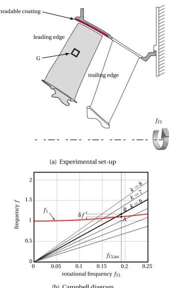
The experimental test-run bench used for the blade-tip/abradable coating application is partially depicted in Fig.2(a)and is detailed in[5]. A full scale experimental multi-stage compressor of an aircraft engine is driven by an electrical motor torque within a vacuum chamber in order to eliminate effects of temperature gradient and aerodynamic loading.
Only the last low-pressure compressor stage has blades, among which one is slightly longer than its counterparts. The interaction phenomenon involves this longer blade, pictured in gray in Fig.2(a), instrumented with a strain gauge (G) located on its suction side. This strain gauge measures the stresses in the middle of the blade along the radial directionσrr. The last stage of the compressor is a downstream guide vane screwed on a heavy frame and the white blade in Fig.2(a)is attached to the casing. An abradable coating facing the blade of interest is sprayed on the casing.
The Campbell diagram of the blade of interest is displayed in Fig.2(b). Because of cen- trifugal stiffening, the first eigenfrequency f1 increases with the rotational frequency fΩ. Beside off1, six engine orders1are indicated.
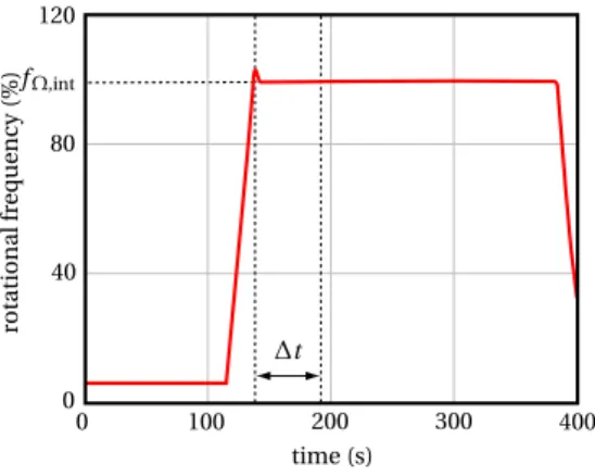
The chosen experimental rotational frequency fΩ is such thatf1=5.5fΩ. Initially ro- tating at low frequency, the compressor undergoes a high acceleration betweent =110 s
1An engine order is defined by the linear relationf=k fΩ,kbeing an integer.
G leading edge
trailing edge
fΩ abradable coating
(a) Experimental set-up
0 0.05 0.1 0.15 0.2 0.25
rotational frequencyfΩ 0
0.5 1 1.5 2
frequencyf
fΩ,int δf
k=8 k=7 k=6 f1
A B
(b) Campbell diagram
Figure 2: Blade of interest
andt =135 s to reach a rotational frequencyfΩ=fΩ,intas shown in Fig.3. Also, the time interval of the interaction∆t is underlined. Blade contact against the casing is achieved through blade elongation caused by centrifugal load.
0 100 200 300 400
time (s) 0
40 80 120
rotationalfrequency(%)fΩ,int
∆t
Figure 3: Rotation speed during the experimental run
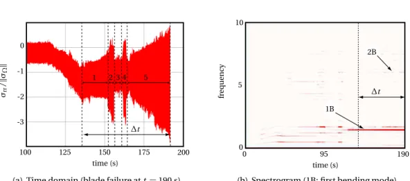
2.2 Results and interaction scenario
100 125 150 175 200
time (s)
1 2 3 4 5
σrr/kσΩk
-3 -2 -1 0
∆t
(a) Time domain (blade failure att=190 s)
0 95 190
time (s) 0
5 10
frequency
1B
2B
∆t
(b) Spectrogram (1B: first bending mode)
Figure 4: Radial stress in the middle of the blade during the experimental run The monitored stress field features five very distinct phases once the targeted rotational frequencyfΩ,intis reached after aboutt =138 s. The five phases of the test are displayed in Fig.4(a):
Phase 1 [fromt =138 s tot = 155 s]As indicated in Fig.5(a), the stress in the blade is periodic around a mean valueσrr,m =−1.18. Figure5(b)shows that the response is dominated by even harmonics suggesting evenly distributed contact occurrences per revolution. The dominant harmonic 2 puts forward a possible ovalization of the
0 TΩ,int
time -1.6
-1.4 -1.2 -1 -0.8
σrr/kσΩk
(a) Time domain
1 2 3 4 5 6 7
harmonic 0
25 50 75 100
normalizedamplitude(%)
(b) Frequency domain
Figure 5: Radial stress in the middle of the blade during the first phase of the interaction casing.
Phase 2 [fromt =155 s tot =158 s]A very sudden and brief increase of the stress level within the blade is observed.
Phase 3 [fromt = 158 s tot = 162 s] A low stress level with constant amplitude is evi- denced.
Phase 4 [fromt =162 s tot =166 s]Observations similar to phase 2 are made. The stress level increases very suddenly.
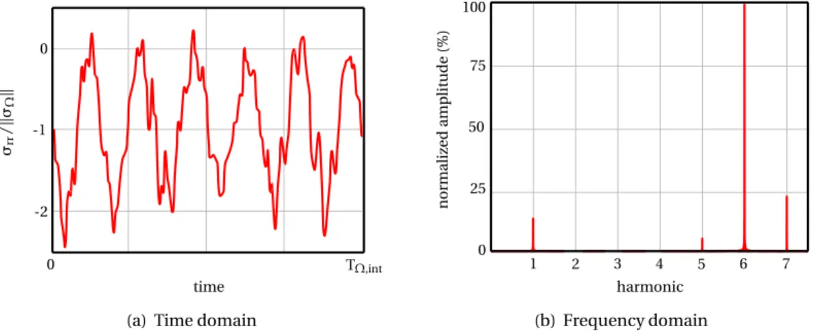
Phase 5 [fromt =166 s tot =190 s]The stress slowly increases until the blade is finally heavily damaged att =190 s when monitoring signal is lost. The respective stress is pictured in Fig.6(a). The harmonic content in Fig.6(b)emphasizes a dominant sixth harmonic.
0 TΩ,int
time -2
-1 0
σrr/kσΩk
(a) Time domain
1 2 3 4 5 6 7
harmonic 0
25 50 75 100
normalizedamplitude(%)
(b) Frequency domain
Figure 6: Radial stress in the middle of the blade during the fifth phase of the interaction
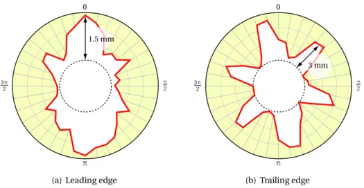
Overall, the spectrogram pictured in Fig.4(b)shows a dominant first bending mode during the five phases of the interaction. Some dots are visible on this spectrogram beforet = 100 s hinting that some blade/casing contacts may have occurred before the interaction starts. The wear levels of the abradable coating are measured on both trailing and leading edges. The two respective wear profiles are plotted in Fig. 7. While two lobes are worn
0
π 2
π 3π
2
1.5 mm
(a) Leading edge
0
π 2
π 3π
2
3 mm
(b) Trailing edge
Figure 7: Wear of the abradable coating measured after the experimental run at the leading edge, six lobes are worn at the trailing edge thus manifesting evidence of complex vibration patterns at the blade tip. In addition, the wear level at the trailing edge is significantly higher than its counterpart on the leading edge: this is consistent with a dominant first bending modal motion as already underlined in Fig.5(a). A modal analysis shows that the maximum radial displacement of the trailing edge is about three times the maximum radial displacement of the leading edge for the first bending mode.
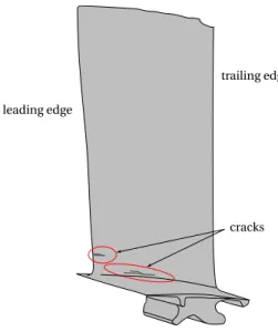
During a careful inspection of the blade after the test run, cracks were found in its root and both its dovetail and trailing edges were damaged similarly to what is pictured in Fig.8.
The blade also exhibited color alteration due to a very local overheating at its tip but its
trailing edge leading edge
cracks
Figure 8: Schematic of the blade after the test (the damages visible on the tip of the blade on the trailing edge are not associated with the interaction phenomenon of interest in our study)
overall temperature did not significantly vary during the experiment. Accordingly, it is un- derstood that dry friction related thermal effects did not affect the dynamics of the blade.
3 Solution method
This section summarizes previous developments on abradable coating modeling, reduced- order model embedding centrifugal effects as well as the contact algorithm[20].
3.1 Finite element model
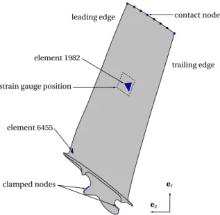
The industrial 3D finite element model is made of 11,339 quadratic tetrahedron elements and contains 22,898 nodes. The two elements where stresses are monitored2— element 1982 in the middle of the blade and element 6455 at the root of the leading edge — as well as the boundary conditions are depicted in Fig.9. The reference frame is attached to the rotating bladed disk and equations of motion are derived within the small perturbation framework. The shaft supporting the bladed disk is perfectly rigid and its axis of rotation is fixed.
The large size of the finite element model would lead to extremely long computation times for explicit time integration simulations. As a consequence, component mode syn- thesis methods are used to reduce the size of the model. The Craig-Bampton[22]proce- dure is applied on the blade. Its compatibility with the contact algorithm we use – detailed in[20]– has been previously studied in[23,10]and its advantages in the context of contact simulations with reduced-order models with respect to other component mode synthesis methods were highlighted in[24,10].
The linear contribution of the centrifugal stiffening effect is here embedded in the reduced- order model of the blade using the development proposed in [25]. The stiffness matrix
2Stresses are computed from the displacements field using the Samcef software. Two types of stresses are considered in this paper: the radial and the von Mises stresses calculated as mean stresses (one value per element).
element 1982
strain gauge position
element 6455
leading edge
trailing edge
clamped nodes
contact nodes
ez er
(a) Boundary conditions and elements of interest
eθ ez er
fΩ fΩ
(b) Mesh
Figure 9: Blade finite element model
K(fΩ)is approximated by a polynomial expansion over a specified rotational frequency rangefΩ∈[0;fΩ,m]such as:
K(fΩ) =K0+fΩ2K1+fΩ4K2 (1)
where:
K0=K(0) K1= 1
3fΩ2,m
16K
fΩ,m
2
−K(fΩ,m)−15K(0)
K2= 3 4fΩ4,m
K(fΩ,m)−4K
fΩ,m
2
+3K(0)
(2)
The Craig-Bampton transformation matrix mapping the reduced-order space to the orig- inal physical one, usually calculated at rest, is here expanded according to Eq. (1). Com- putation of the reduced-order model is then carried out using three modal reduction bases calculated forfΩ=0,fΩ=fΩ,m/2 andfΩ=fΩ,m, respectively, which yields the following transformation matrixΦ:
Φ=
I 0 0 0 0 0
ΦR(0) ΦR
f
Ω,m 2
∗
ΦR(fΩ,m)∗ ΦL(0) ΦL
f
Ω,m 2
ΦL(fΩ,m)
(3) where matricesΦR(fΩ)andΦL(fΩ)stand for thenc constraint modes and theηfixed- interface modes computed at fΩ, respectively. Superscript∗indicates that matrixΦR(0) is subtracted: A∗ =A−ΦR(0). MatrixΦin Eq. (3) defines the projection used to reduce the size of the investigated system. It is potentially rank-deficient because of similarities between the calculated constraint modes. An orthonormalization which relies on a singular value decomposition is thus performed. It yields a reduction of the rank and the maximum dimension of the subsequent reduced-order model isn=3η+3nc.
Accordingly, the equation of motion is projected onto the newly built reduced-order space as follows:
u=
ub
ui
=
I 0 ΦR(0) Ψ
ub
q
(4) As deduced from Eq. (4), the contact constraints — that are only applied onub — can di- rectly be treated in the reduced space if the anticipated contact locations are defined as interface nodes, thus avoiding permanent forward and backward mappings to the physical space. This is a major feature motivating the choice of the Craig-Bampton technique.
In this study, eight nodes, numbered from the leading edge to the trailing edge as il- lustrated in Fig.9, define the discretized contact interface. To ensure linear modal conver- gence, at least six component modes are required for each of the three considered rota- tional frequencies fΩ and the final size reduced-order model of the blade is 85 DoF. It is considered that linear modal convergence is reached when the difference between the first N eigenfrequencies of the finite element model and the corresponding eigenfrequencies of the reduced-order model is less than 1%.
0 0.1 0.2 0.3 0.4 0.5
rotational frequencyfΩ 0
2 4 6
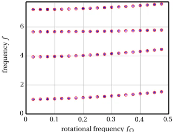
frequencyf
Figure 10: Superimposition of the Campbell diagrams of the reduced order model (+) and the finite element model (o). All frequencies are normalized with respect to the first eigen- frequency of the blade at rest.
The performances of the computed reduced-order model are characterized by com- paring the resulting Campbell diagram to the Campbell diagram of the full finite element model. These two diagrams are perfectly similar for the four first eigenfrequencies of the blade as depicted in Fig.10.
3.2 Plastic law
The characterization of dynamical properties of the abradable material is still under investi- gation and to our knowledge only two numerical models exist in the literature[15]and[20], which is used in this paper, for the numerical modeling of abradable coating.
The abradable material is discretized with one-dimensional two-node rod elements as pictured in Fig. 11. More details regarding the computation of contact effortsFmay be found in[20]. The plasticity constitutive law controlling the ductility of the abradable coat- ing is depicted in Fig.12where the three numerical parameters of the law are highlighted:
the Young’s modulus E, the plastic modulus K and the yield limitσY.
The determintation of these three parameters is based on industrial experience and are not given here for the sake of confidentiality.
rigid casing
rigid casing
bar element super element
fΩ fΩ
abradable profile abradable
blade
contact nodes Fp
F1 F
Figure 11: Blade interface node and associated geometrical profile
ǫp
ǫ σ
σY
E
K
Figure 12: Plasticity constitutive law.
3.3 Numerical assumptions
In contrast to experimental conditions, assumptions in the numerical simulation are as follows:
• The rotational velocity is constant.
• Contact between the blade and the casing is initiated through an ovalization of the casing to reflect a thermal gradient in the casing. This ovalization does not account for manufacturing imperfections. The maximum radial displacement isdmax=2c0
wherec0is the blade-tip/casing clearance at rest with a perfectly circular casing. This time-dependent ovalization is pictured in Fig.13and is defined as:
evol(t) =1−eαt (5)
• The casing is not sensitive to the interaction and is modeled as a rigid mathematical surface over which the abradable coating is deposited.
• The abradable properties of the coating are modeled using a plastic law[20]. This law includes three mechanical parameters: the Young’s modulus E, the plastic modulus K and the yield strengthσY.
• Only one longer blade involved in the interaction is modeled in the proposed numer- ical tool with a clamped displacement on its root as boundary conditions.
• A component mode synthesis approach compatible with contact conditions was used[10, 24]. This method embeds centrifugal effects directly within the reduced-order model[20].
0 10T∗Ω,int 20T∗Ω,int time
0 20 40 60 80 100
casingovalization(%)
t=t99%
Figure 13: Amplitude of casing ovalization
Eight contact nodes illustrated in Fig.9are defined along the blade tip from the lead- ing edge to the trailing edge.
4 Numerical investigation
Numerical simulations are carried out around the experimental rotational frequencyfΩ,int. An interaction phenomenon arises forfΩ∗,int≃fΩ,int×1.05 and the associated period is de- noted TΩ∗,int. The differences between numerical and experimental rotational frequencies where interaction arises most probably emanate from the aforementioned numerical as- sumptions.
The simulation corresponds to twenty revolutions. This is obviously shorter than the to- tal duration of the experiment but is sufficient to numerically observe the interaction phe- nomenon. The ovalization amplitude with respect to time is pictured in Fig.13. The time for which the maximum radial displacement reaches 0.99dmaxis denotedt99%. Equation (5) yieldst99%=ln(0.01)/α. For the solicitation considered in our study, results presented in the sequel do not depend onα.
4.1 General observations
The tangential displacement at the trailing edge is depicted in Fig.14(a)where two phases are defined: (1) fort ≤t99%the displacement amplitude increases quickly (slopes1) due to the ovalization of the casing and (2) fort≥t99%the amplitude grows almost linearly (slope s2) while the casing has already reached its final shape. Two respective time segments are considered in the following:t ∈[0;t99%]andt >t99%which will be respectively referred to asphase 1andphase 2.
A spectrogram of the tangential displacement of the contact node at the trailing edge is depicted in Fig.14(b). The first bending mode is dominant, in agreement with experimental observations and the spectrogram in Fig.4(b).
4.1.1 Phase 1
Phase 1 corresponds to the first four revolutions during which the casing is being ovalized.
The von Mises stress in element 1982 over the first two revolutions is pictured in Fig.15. Its mean value increases because of the casing ovalization.
Stressσrrin element 1982 during the second revolution is depicted in Fig.16(a)together with its harmonic content shown in Fig.16(b). It is worth noticing that the normalized
0 10T∗Ω,int 20T∗Ω,int time
-1 -0.5 0 0.5 1
displacement
t=t99%
s1 s2
frequency
(a) Time histories
nt 0 10TΩ∗,int 20T∗Ω,int
time 0
5 10 15 20
frequency
1B 1T 2B
t=t99%
(b) Spectrogram; 1B: first bending mode; 1T: first tor- sion mode; 2B: second bending mode
Figure 14: Tangential displacement of the contact node at the trailing edge
0 TΩ,int∗ 2T∗Ω,int time
1 1.24 1.48 1.72 1.96 2.20
σvm/kσΩk
1 revolution 1 revolution
Figure 15: von Mises stress in element 1982 versus the first two revolutions of the blade following the first blade-tip/abradable contact
T∗Ω,int 2TΩ,int∗
time -1.6
-1.3 -1 -0.7 -0.4
σrr/kσΩk
(a) Time domain
1 2 3 4 5 6 7
harmonic 0
25 50 75 100
normalizedamplitude(%)
(b) Frequency domain
Figure 16: Radial stress in the middle of the blade (element 1982) during phase 1 mean value of σvm/kσΩk is about−0.9, the same order of magnitude as experimental σrr,m = −1.18 mentioned in section 2.2. Also, the harmonic content in Fig. 16(b) high- lights preponderant even harmonics in partial concordance with the experimental results in Fig.5(b). Though it is noticeable that the dominant harmonic in not the same in these two figures. It is a fact that most of the numerical approximations in our study impact the
first numerical phase (among which the relatively fast ovalization of the casing and a con- stant rotational velocity) and could explain this difference.
4.1.2 Phase 2
Amplitudes of vibration grow linearly during the second phase as pictured in Fig.14(a).
Stressσrrin element 1982 during revolution 8 is depicted in Fig.17(a). Its mean amplitude is about−1 which is in good agreement with the last experimental phase in Fig.6(a). Exper- imental and numerical stresses in the frequency domain depicted in Figs. 6(b)and17(b), respectively, feature similar pattern with an apparent sixth harmonic.
7T∗Ω,int 8T∗Ω,int
time -2
-1 0
σrr/kσΩk
(a) Time domain
1 2 3 4 5 6 7
harmonic 0
25 50 75 100
normalizedamplitude(%)
(b) Frequency domain
Figure 17: Radial stress in the middle of the blade (element 1982) during phase 2 These results highlight the good agreement between numerical simulations and exper- imental observations during the last interaction phase. In the following, the numerical tool is employed to provide access to quantities that were not experimentally available such as the stress level in the blade root.
4.1.3 Other predicted quantities
Attention is first paid to the von Mises stress within element 6455 indicated in Fig.9. This stress is pictured in Fig.18(a). It shows that the mean stress magnitude is about 2.8 which is about three times higher than the average radial stress in the middle of the blade. The fre- quency domain plot in Fig.18(b)emphasizes the presence of a dominant twelfth harmonic in the blade response. Frequency difference between Fig.17(b)and Fig.18(b)stems from the type of stress considered: radial stress versus von Mises stress. Portrayed numerical ev- idence of possibly high cycle fatigue conditions supports the idea of crack propagation ini- tiated at stress-concentration sites due to endurance limits[26]. Complemented with a full stress field map of the blade, three critical areas — as pictured in Fig.19fort =7.45T∗Ω,int
— are detected. It is worthy to note that these zones match very well with the experimental damaged areas depicted in Fig.8. In particular, a peak of stress occurs in the blade root.
The final wear profiles at the leading and trailing edges are plotted in Figs.20(a)and20(b).
The similarities with the experimental profiles pictured in Figs.7(a)and7(b)are patent and the discrepancy in the magnitude of the lobes may be the consequence of the numerically simplified blade-tip/casing configuration. Both experimental and numerical result exhibit a higher wear level at the trailing edge in agreement with a dominant first bending mode in the blade dynamics. At the trailing edge, it is also noticeable that both experimental and numerical results exhibit a degenerated six-lobe profile with four smaller extra lobes. In ad- dition, an identical phase shift between the position of maximum wear at the trailing edge
7T∗Ω,int 8T∗Ω,int time
1 2.22 3.44 4.66
σvm/kσΩk
(a) Time domain
2 4 6 8 10 12
harmonic 0
25 50 75 100
normalizedamplitude(%)
(b) Frequency domain
Figure 18: von Mises stress in blade root (element 6455) during phase 2
1 1.61 2.22 2.83 3.44 4.05 4.66 5.27 5.88 6.49 7.1 σvm/kσΩk
Figure 19: von Mises stress field fort =7.45T∗Ω,int
(θ=0 rad) and at the leading edge (θ≃ −0.21 rad) can be observed. This phase shift stems from the blade angular widthδθ=0.22 rad around the axis of rotation.
The fact that a fairly simple model is capable to predict a rather complicated interaction phenomenon indicates that the latter is probably robust, i.e. it is likely to occur under a va- riety of realistic conditions. Accordingly, its sensitivity to the abradable material properties and to the geometry of the blade is now explored.
5 Exploratory investigations
5.1 Alteration of the abradable mechanical properties
The sensitivity of the blade vibratory amplitudes to the mechanical properties of the abrad- able coating was addressed in [20,21]where a worst case scenariofeaturing large ampli- tudes of displacement was identified. The continuous and gradual removal of the abrad- able liner observed for intermediate Young’s and plastic modulii was underlined as a possi- ble key feature in the interaction phenomenon outbreak.
In order to further investigate the complex relationship between blade vibration and
0
π 2
π 3π
2
1.2 mm
(a) leading edge
0
π 2
π 3π
2
2.2 mm
(b) trailing edge
Figure 20: Wear of the abradable coating computed with numerical simulations abradable removal, this section focuses on a sudden alteration of its mechanical properties.
Two configurations are considered: (1) at t = t99% the Young’s modulus is suddenly de- creased to E/100 and (2) att =t99%the Young’s modulus is suddenly increased to E×100.
0 50TΩ∗,int 100T∗Ω,int time
-2 -1 0 1 2
displacement
t=t99%
(a) E→E/100 att=t99%
0 50T∗Ω
,int 100T∗Ω,int
time -2
-1 0 1 2
displacement
t=t99%
separation
(b) E→E×100 att=t99%
Figure 21: Tangential displacement of the contact node at the trailing edge; Sudden alter- ation of the Young’s modulus ( ) and reference solution ( )
The new scenario is compared to the reference solution in Figures 21(a) and 21(b).
When E decreases, the abradable material is too ductile to significantly affect the blade dy- namics fort >t99%and the vibration of the blade decays. When E is increased, mechanical contacts lead to constantly growing vibratory levels untilt ≃40TΩ∗,intwhere separation oc- curs. The respective vibratory pattern looks similar to the end of experimental phases 2 and 4, as depicted in Fig.4(a). The corresponding wear profile at the trailing edge is pictured in Figs.22(a)and22(b). When the Young’s modulus E is decreased, the abradable coating acts as an purely elastic material in equilibrium with the blade and the worn lobes will no longer expand as illustrated in Fig.22(a). When E is increased, the maximum wear level is slightly higher than the one for the reference solution as shown in Fig.22(b)and the shape of the lobes tends to fade away. The overall scenario of interaction when E is increased can be described as follows:
contact initiation: blade/abradable coating contact is initiated by casing ovalization and a first bending mode dominates. The blade rotates atfΩ∗,int≃f1/6 and six small worn lobes are observed in the liner att =t99%;
0
π 2
π 3π
2
(a) E→E/100 att=t99%
(a) E→E/100 att=t99%
0
π 2
π 3π
2
δφ
(b) E→E×100 att=t99%
(b) E→E×100 att=t99%
Figure 22: Abradable coating removal at the trailing edge after 100 revolutions; Alteration of the Young’s modulus ( ) and reference solution ( )
amplification: fromt = t99% tot ≃40T∗Ω,int, repeated contacts lead to a progressive re- moval of the coating within the six lobes and vibration grows. Due to the Young’s modulus alteration, the blade synchronization at fΩ∗,int is lost and the position of lobes tends to slowly rotate: angleδφin Fig.22(b)denotes this deviation;
decay of the worn lobes: aroundt ≃40T∗Ω,int, the liner is evenly abraded away and original lobes have disappeared;
separation: fort ≥40TΩ∗,int, the synchronization on the first bending mode is lost and vi- bration is damped out.
These results raise the question of possible occurrences of blade desynchronization during the experimental run at the end of phases 2 and 4 due to a modification of the properties of the abradable layer. In this light, one may wonder why a synchronization is possible during the last interaction phase, then leading to divergence and failure. This cannot be answered now but one may speculate on the necessity to account for non-constant plastic and Young’s modulii K and E during the simulation. With the addition of the flexibility of the surrounding fan-case, this would set a more general framework suitable for a thorough understanding of the interaction phenomenon.
5.2 Improved Blade designs
The sensitivity of the interaction phenomenon to the blade design is now addressed. To this end, three geometries displayed in Fig.23are investigated. They feature an additional curvature which tends to open the clearance during a contact occurrence and are only gen- erated based on structural considerations, aerodynamic performances are ignored for in this study.
For each design, simulations are carried out with the same contact configuration as the one described in section4over a wide rotational frequency range. The wear profiles on the trailing edge computed for each simulation are extracted and juxtaposed to draw the wear maps pictured in Fig.24.
The design modification implies a shift of the blade eigenfrequencies explaining why the interaction phenomenon arises at distinct rotational frequencies for each profile. More
Bow IT3 Winglet
Figure 23: Blade design evolutions superimposed to the reference design.
0.05 0.05 0.05
0.05 0.175
0.175 0.175
0.175 0.3
0.3 0.3
0.3
0 0 0
0
π π π
π
2π 2π 2π
2π
angularposition(rad)angularposition(rad)
angularposition(rad)angularposition(rad)
reference design Bow
IT3 Winglet
rotational frequencyfΩ rotational frequencyfΩ rotational frequencyfΩ
rotational frequencyfΩ
wearlevel(mm)
0 0.4 0.8 1.2 1.6 2 fΩ,int
Figure 24: Maps of worn lobes at the trailing edge for different blade geometry specifically, the six-lobe profile detected forf =fΩ,intwith the reference design almost van- ishes with the Bow design while it is shifted and reduced with the IT3 and Winglet designs.
It is remarkable that the reference profile features the most complex wear map with a very high number of critical velocities for which appear a specific number of worn lobes.
The three design modifications depicted in Fig.23favor clearance opening when con- tacts occur and highly affect the contact conditions. While opening clearances is a fre-
quently adopted strategy in the industry when large amplitudes of vibration are detected in one stage of a turbomachine, it also implies a diminution of the energy efficiency and thus cannot be implemented on a large scale.
The sensitivity of the interaction phenomenon to blade design suggests that it could be advantageously considered during the design stage of the blades.
6 Conclusion
In this study, consideration is given to the numerical simulation of a rotor/stator interac- tion case experimentally observed while abradable coating had been deposited over the casing circumference. The rotational frequency is approximately a sixth of the first eigen- frequency of the blade. Experimental results reveal a damaged blade — three critical areas are identified — and a singular wear pattern on the abradable coating with two worn lobes at the leading edge and six deeper worn lobes at the trailing edge. Furthermore, frequency domain results underline the dominance of the first bending mode.
Based on a numerical strategy previously introduced, the interaction case is simulated with a reduced 3D finite element model of the blade. First of all, it is highlighted that the blade dynamics is accurately captured numerically since the experimentally observed dom- inant first bending mode is well described. The numerically predicted stress levels in the middle of the blade corroborate the measurement results and exhibits a dominant sixth harmonic. This is in concordance with the rotational frequency and the blade is said to be synchronized. The respective measured wear profiles are very similar to the predicted ones:
two intermediate lobes at the leading edge and six deeper lobes at the trailing edge are found. In addition, critical areas with maximum stress levels within the blade are predicted where cracks and missing parts were experimentally diagnosed.
A more in-depth and exploratory analysis of the interaction phenomenon is performed in order to identify critical parameters in the outbreak of the interaction. First results sug- gest that the sudden jumps in the amplitude of vibration experimentally measured could be associated with desynchronization of the blade on its first bending mode due to an alter- ation of the abradable mechanical properties.
The sensitivity of the interaction to the blade geometry is also addressed. The proposed designs lead to lower displacements and the number of critical rotational frequencies for which arises the interaction phenomenon is significantly reduced over the rotational fre- quency range of interest. Obtained results suggest that the outbreak of the interaction phe- nomenon reported in[5]is closely related to three factors: (1) blade design, (2) material properties of the abradable coating and (3) a global deformation of the casing.
Acknowledgment
Thanks go to Snecma for its technical and financial support. This work takes place in the framework of the MAIA mechanical research and technology program sponsored by CNRS, ONERA and SAFRAN Group.
References
[1] Morfey, C. L., 1964. “Rotating pressure patterns in ducts: their generation and transmission”. Journal of Sound and Vibration,1(1), pp. 60 – 87.
[2] Arndt, N., Acosta, A. J., Brennen, C. E., and Caughey, T. K., 1990. “Experimental investigation of rotor-stator interaction in a centrifugal pump with several vaned diffusers”. Journal of Turbomachinery,112, pp. 98 – 108.
[3] Dring, R. P., Joslyn, H. D., Hardin, L. W., and Wagner, J. H., 1982. “Turbine rotor-stator interaction”.Journal of Engineering for Power,104, pp. 729 – 742.
[4] Trébinjac, I., and Vixège, C., 2002. “Experimental analysis of the rotor stator interaction within a high pressure centrifugal compressor”. Journal of Thermal Science,11, pp. 1 – 9.
[5] Millecamps, A., Brunel, J. F., Dufrénoy, P., Garcin, F., and Nucci, M., 2009. “Influence of thermal effects during blade-casing contact experiments”. In Proceedings of the ASME IDETC/CIE - DETC2009-86842.
[6] Park, M., Hwang, Y.-H., Choi, Y.-S., and Kim, T.-G., 2002. “Analysis of a j69-t-25 engine turbine blade fracture”.Engineering Failure Analysis,9, pp. 593 – 601.
[7] Xie, Y.-J., Wang, M.-C., Zhang, G., and Chang, M., 2006. “Analysis of superalloy turbine blade tip cracking during service”. Engineering Failure Analysis,13, pp. 1429 – 1436.
[8] Schmiechen, P., 1997. “Travelling wave speed coincidence”. Ph.D. thesis, College of Science, Technology and Medicine, London, UK. ISBN-13: 978-3183260119.
[9] Legrand, M., Pierre, C., Cartraud, P., and Lombard, J.-P., 2009. “Two-dimensional modeling of an aircraft engine structural bladed disk-casing modal interaction”.
Journal of Sound and Vibration,319(1-2), pp. 366 – 391.
[10] Batailly, A., Legrand, M., Cartraud, P., and Pierre, C., 2010. “Assessment of reduced models for the detection of modal interaction through rotor stator contacts”.Journal of Sound and Vibration,329, pp. 5546–5562.
[11] Emery, A. F., Wolak, J., Etemad, S., and Choi, S. R., 1983. “An experimental
investigation of temperatures due to rubbing at the blade-seal interface in an aircraft compressor”. Wear,91, pp. 117 – 130.
[12] Padova, C., Barton, J., Dunn, M., and Manwaring, S., 2007. “Experimental results from controlled blade tip/shroud rubs at engine speed”.Journal of Turbomachinery, 129(4), pp. 713 – 723.
[13] Muszynska, A., 1986. “Whirl and whip–rotor/bearing stability problems”.Journal of Sound and Vibration,110(3), pp. 443 – 462.
[14] Childs, D. W., and Bhattacharya, A., 2007. “Prediction of dry-friction whirl and whip between a rotor and a stator”. Journal of Vibration and Acoustics,129, pp. 355 – 362.
[15] Williams, R. J., 2011. “Simulation of blade casing interaction phenomena in gas turbines resulting from heavy tip rubs using an implicit time marching method”. In Proceedings of the ASME Turbo Expo 2011, GT2011-45495.
[16] Ma, X., and Matthews, A., 2009. “Evaluation of abradable seal coating mechanical properties”.Wear,267, pp. 1501–1510.
[17] Yi, M., J., H., Huang, B., and Zhou, H., 1999. “Friction and wear behaviour and abradability of abradable seal coating”. Wear,231, pp. 47–53.
[18] Bounazef, M., Guessasma, S., and B., A. S., 2004. “The wear, deterioration and transformation phenomena of abradable coating bn-sial-bounding organic element, caused by the friction between the blades and the turbine casing”.materials letters, 58, pp. 3375–3380.
[19] Peyraut, F., Seichepine, J. L., Coddet, C., and Hertter, M., 2008. “Finite element modeling of abradable materials - identification of plastic parameters and issues on minimum hardness against coating’s thickness”. International Journal for Simulation and Multidisciplinary Design Optimization,2, pp. 209–215.
[20] Legrand, M., Batailly, A., and Pierre, C., 2012. “Numerical investigation of abradable coating removal through plastic constitutive law in aircraft engine”.Journal of Computational and Nonlinear Dynamics,7.
[21] Batailly, A., Legrand, M., and Pierre, C., 2011. “Influence of abradable coating wear mechanical properties on rotor stator interaction”. In Proceedings of the ASME Turbo Expo 2011 - GT2011-45189.
[22] Craig, R. R., and Bampton, C. C., 1968. “Coupling of substructures for dynamics analyses”. AIAA Journal,6(7), pp. 1313 – 1319.
[23] Batailly, A., Legrand, M., Cartraud, P., Pierre, C., and Lombard, J. P., 2007. “Study of component mode synthesis methods in a rotor-stator interaction case”. Proceedings of the ASME 2007 International Design Engineering Technical Conferences &
Computers and Information in Engineering Conference: IDETC07, September 2007, Las Vegas, Nevada.
[24] Batailly, A., 2008. “Simulation de l’interaction rotor/stator pour des turbomachines aéronautiques en configuration non-accidentelle”. Thèse de doctorat, École Centrale de Nantes, Nantes, France.
http://tel.archives-ouvertes.fr/tel-00364945/en/.
[25] Sternchüss, A., and Balmès, E., 2006. “On the reduction of quasi-cyclic disks with variable rotation speeds”.Proceedings of the International Conference on Advanced Acoustics and Vibration Engineering (ISMA), pp. 3925–3939.
[26] Chakravorty, P. K., Bhujanga Rao, V., Murthy, K. V. V. S. S., and Unnikrishnan, T., 1981.
“Vibration signature analysis of shipboard machinery”.Defence Science Journal,32(1), pp. 9–16.