HAL Id: hal-00849440
https://hal.archives-ouvertes.fr/hal-00849440
Submitted on 31 Jul 2013
HAL
is a multi-disciplinary open access archive for the deposit and dissemination of sci- entific research documents, whether they are pub- lished or not. The documents may come from teaching and research institutions in France or abroad, or from public or private research centers.
L’archive ouverte pluridisciplinaire
HAL, estdestinée au dépôt et à la diffusion de documents scientifiques de niveau recherche, publiés ou non, émanant des établissements d’enseignement et de recherche français ou étrangers, des laboratoires publics ou privés.
Phenomenological continuous contact-impact modelling for multi-body simulations of pedestrian-vehicle contact
interactions based on experimental data
Robert Wg Anderson, Alexandra Long, Thierry Serre
To cite this version:
Robert Wg Anderson, Alexandra Long, Thierry Serre. Phenomenological continuous contact-impact
modelling for multi-body simulations of pedestrian-vehicle contact interactions based on experimental
data. Nonlinear Dynamics, Springer Verlag, 2009, 58 (1/2), p199-208. �hal-00849440�
Phenomenological continuous contact-impact modelling for multi-body simulations of pedestrian-vehicle contact interactions based on
experimental data
Robert W. G. Anderson
1, Alexandra D. Long
1and Thierry Serre
2October 9, 2008
1Centre for Automotive Safety Research, The University of Adelaide, AUS- TRALIA
2Laboratoire de Biomécanique Appliquée, Institut National de Recherche sur les Transports et leur Sécurité, Université de la Méditerranée, FRANCE
Abstract
Multibody modelling of pedestrian collisions requires the definition of contact- impact between the pedestrian and the vehicle. An examination of relevant impact test data reveals large rate-dependent components of the reaction force, permanent indentation, and concomitant energy loss. Contact-impact models previously used in simulations of pedestrian impacts typically have not ade- quately modelled one, two or all three of these phenomena. This paper presents a phenomenological contact-impact model based on the Hunt-Crossley model of impact, which includes rate-dependent damping, and is extended to include permanent indentation. The proposed model suitably characterises impact test data in a form that can also be implemented in the multibody simulation code MADYMO (Tass-Safe, Netherlands). The proposed contact-impact model was used to characterise the impact between a legform and the bumper of a vehi- cle, based on two impact tests conducted at different impact speeds. A single contact-impact definition in MADYMO closely reproduced the dynamics of both tests. The proposed model may be suitable in a wide range of impact conditions where the impact is modelled using multibody techniques and it is practicable to conduct impact tests as part of the modelling process.
Non Linear Dynamics, Vol 58, Numbers 1-2, octobre 2009, Pp 199-208 DOI : 10.1007/s11071-009-9471-6
Copyright © Springer Netherlands http://www.springerlink.com/content/102972/
Keywords: contact-impact properties, impact test, multibody simulation, non- linear damping, pedestrian collisions
Nomenclature
δ Contact penetration
δm Maximum penetration δp Permanent indentation δ˙0 Impact velocity
c Hunt-Crossley damping parameter e Coefficient of restitution
F Normal contact impact force Fm Force at maximum penetration K Hertzian stiffness parameter n Hertzian stiffness index
1 Introduction
Multibody modelling is being used extensively in the reconstruction and simu- lation of collisions between pedestrians and motor vehicles. The objectives of such studies include the simulation of experiments with post-mortem human subjects [1], the comparison between simulation models and pedestrian anthro- pomorphic test devices [2, 3], the influence of vehicle design on pedestrian injury [3, 4], the reconstruction of actual crashes [5, 6, 7, 8, 9, 10], and the study of injury mechanisms and injury tolerances [11, 12]. The studies have, in common, an objective to validly estimate pedestrian dynamics in a collision. While there has been some focus on improved characterisation of the kinematic properties of the pedestrian (e.g. [1, 13]) there has been less focus on the contact-impact properties of the interaction between pedestrian and vehicle, and existing char- acterisations may be less than ideal. The purpose of this paper is to examine typical pedestrian test impact data and to demonstrate the characterisation of such data using an appropriate continuous contact-impact model. Further, the implementation of such a model in the multibody simulation software package
MADYMO (Tass-Safe, Netherlands) is demonstrated. The emphasis on the im- plementation in MADYMO is made here as MADYMO is currently the most commonly used code for multibody simulations of pedestrian collisions [1-10].
Vehicle stiffness characteristics in pedestrian collision simulations are often based on experimental data. It is clear from such data that energy loss (damp- ing) is an important characteristic of all such impacts. One method of incorpo- rating experimentally determined energy loss in a pedestrian impact simulation is typified by the method employed by van Rooij et al. [5]. Their method ap- proaches the problem by examining force-deflection data from impact tests and then treats such data as containing a fixed loading phase (which consists of an increasing load in the presence of an increasing deflection but also often a second loading phase where there is a generally decreasing load in the presence of an increasing deflection), and an unloading phase (defined by a generally decreas- ing load in the presence of a decreasing deflection) with unloading complete at some finite permanent deformation. If no other damping is defined, energy loss is handled only by the explicit definition of this hysteresis loop. While such an ap- proach may be successful in the simulation of the test condition that was used to derive the characteristic, there may be problems when the contact-impact model must be applied to an impact under different conditions. For example, many impact data produced from pedestrian subsystem tests clearly have the characteristic of rate-dependent damping: such data are characterised by a force at peak deflection (when the indentation velocity is zero) that is less than the peak impact force [14]. The European Passive Safety Network (APROSYS) published corridors for the frontal stiffness of the current European fleet from EuroNCAP pedestrian subsystem tests [15, 16], and such data clearly show such rate dependent damping effects. Therefore, when applied to the simulation of impacts at speeds that are different from the test speed, an explicit definition of the hysteresis loop will fail to account for this rate dependent effect. Even as defined, the extrapolation or interpolation of explicitly defined loading and unloading curves may have other unintended effects.
Another method is typified by [4]. Here, the contact loading force is defined as a linear stiffness function of penetration. Damping may be included by the inclusion of an unloading stiffness, sometimes at some set fraction of the loading stiffness (e.g. [3]), and a hysteresis slope that is used to connect the loading curve at peak displacement with the unloading curve. This approach may yield a contact with predictable energy loss, but will inevitably produce unrealistic force-time data due to the inherent discontinuities in the contact definition.
Also, while energy loss may be correctly accounted for, it is unlikely that this can be achieved simultaneously with correct estimations of other parameters such as peak force.
An alternative approach for the characterisation of pedestrian vehicle con- tacts was suggested by [17] and [18], based on earlier work by Lankarani and Nikravesh [19] (explained in detail below), but the approach does not account for energy loss due to permanent deformation, and appears not to have been taken up by others in the pedestrian crash simulation field.
In practice, for the multibody simulation of pedestrian impacts, the precision with which contact behaviour is defined will depend on the purpose of defining the contact in the first place. If the purpose of the contact is to simulate energy loss from the impact, it may be sufficient to ensure that the coefficient of restitution is accurate. But such a simple approach may render the simulation useless for the examination of the contact forces themselves.
Where the contact will be used to make injury risk assessments, especially those such as the Head Injury Criterion that are calculated from the pulse, the details of the contact behaviour will determine the pulse shape and are therefore critical to the assessment. Furthermore, in parametric or stochastic models, it becomes important to understand rate-dependent effects as impact velocity will usually vary over the solution space: unless the dependence on velocity is known, the dynamics of the simulation and the assessment of injury risk will become less precise as the difference between the simulation impact speed and the speed at which the impact properties of the interaction were measured becomes greater.
We have previously established that the effective stiffness of pedestrian sub- system impacts is non-linear with respect to impact speed and that it is possible to account for the effects of velocity using damping [6]. However, while prac- ticable, that implementation lacked a theoretical basis and was ad-hoc. This paper presents a method to:
• characterise impact test data according to the contact-impact model de- veloped first by Hunt and Crossley [20] adapted to include permanent indentation, and then to
• implement the model in MADYMO.
The ability of the model to characterise a contact is demonstrated by applying it to the simulation of two physical impacts conducted at different speeds between a legform impactor and the bumper of a vehicle.
A similar treatment for the impact between two beams of known properties has been provided elsewhere, but where the impact velocity was not known [21]. Here, we present a method of characterising the interaction between two bodies where it is assumed that the impact velocity in a test is known and force-deflection data are recorded.
2 Background theory
In many multibody applications, Kelvin-‘ contact models are unsuitable for modelling rate dependent effects on the impact between two bodies. Prob- lems with using the Kelvin-Voigt model include the instantaneous production of damping force at the initialisation of contact, and damping forces that create tension between the colliding bodies during the restitution phase [20].
Hunt and Crossley [20] proposed an alternative damping model which is an extension of Hertz’s contact theory. The Hertz contact law,
F =Kδn (1)
is extended to include a non-linear damping term:
F =Kδn+bδpδ˙q (2)
Hunt and Crossley setp=nand suggest thatq= 1. This model of damping is often referred to as Hunt-Crossley damping. A distinctive feature of this model is that the damping forces are zero at the beginning and end of the impact.
Lankarani and Nikravesh [19] showed that, in the case of Hertzian impact between two spheres, bcan be related to the contact speedδ˙0, stiffnessK and coefficient of restitutione:
b= 3 1−e2 K 4 ˙δ0
and so settingp=nit is possible to write Equation 2 as F =Kδn
"
1 +3 1−e2δ˙q 4 ˙δ0
#
(a form of the equation presented in [17] and [18]) or F =Kδnh
1 +cδ˙qi
(3) where
c= 3(1−e2)/4 ˙δ0 (4)
Note that Equation 4 assumes that the damping energy is much less than the maximum elastic energy, and there is no plastic deformation [19]. The damping parameterc is not independent of the impact velocity: not only isc inversely proportional toδ˙0, but the coefficient of restitution often depends on the impact velocity [23, 24].
The Hunt-Crossley contact-impact model does not account for energy loss due to plasticity and presents a limitation in the use of Equation 3 in simula-
tions where permanent indentation, and the associated energy loss, is important.
Lankarani and Nikravesh [19] (and others as detailed in [25]) proposed that the hysteretic behaviour of an undamped Hertzian impact with permanent defor- mation can be described by
F =Fm
δ−δp
δm−δp
n
(5) where the subscript m refers to values at peak penetration and subscript p refers to the residual deformation after the impact. Gilardi and Sharf [24]
suggest that Equation 5 has not been widely used to solve multibody contact problems because the requirement of a priori knowledge of δm and δp make it somewhat cumbersome to use. However, such information is readily acquired from an impact test.
Recognising thatFm=Kδmn, Equation 5 may be rewritten as F =K
δm
δm−δp
(δ−δp) n
It is apparent that the inclusion ofδm and δp affects the Hertzian stiffness parameter, and the intercept of the force-deflection relationship. However it is also apparent that Equation 5 conforms to the Hertzian force-displacement relationship, which suggests that damping may be included in the unloading phase by adding damping in an analogous way as presented in Equation 3, i.e.:
F =K δm
δm−δp
(δ−δp) n
h1 +cδ˙qi
(6) To summarise, whenq= 1, the proposed model can be written as
F=
Kδn[1 +cδ],˙ δ˙≥0 Kh
δm
δm−δp(δ−δp)in
[1 +cδ],˙ δ˙≤0 (7) This model will be referred to as the Hunt-Crossley model of contact-impact with permanent indentation. Note that because of the additional energy loss due to plasticity, c will no longer conform to Equation 4. In the following section, it will be shown howcmay be estimated from experimentally produced impact data directly, without resorting to finding an analogous expression to Equation 4. (An attempt at deriving such an expression is made in [26].) This will also have the added advantage of dispensing with the assumption that the damping energy is a small proportion of the total energy absorbed in the approach phase of the impact.
As mentioned above, Hunt and Crossley note in [20] that, whenq = 1,cis
independent of Hertzian stiffness index n. In other words, it is independent of the force-deflection relationship. This implies that a further generalisation of the damped loading and unloading phases of impact suggested by Equation 7, whenq= 1, is given by
F=
Fe−load[1 +cδ],˙ δ˙≥0
Fe−unload[1 +cδ],˙ δ˙≤0 (8) whereFe−∗is a force-deflection relationship that fits the empirical force data.
While a Hertz contact law was used originally to derive Equation 3, we posit that the relationship expressed in Equation 8 is equally valid whenq= 1, as long as the loading and unloading functions comply with the initial condition that Fe−load= 0atδ= 0 [20], the intermediate condition thatFe−load=Fe−unload
atδ=δm, and the final condition thatFe−unload= 0atδ=δp. For example,
Fe=
A(ebδ−1) 0≤δ ≤δm,δ˙≥0
A(ebδm(δ−δp)/(δm−δp)−1) δm≥δ≥δp,δ˙≤0 (9) satisfy these conditions. The form of Equation 9 is similar to the empirical contact-impact relationship used in one particular application by Lankaraniet al. [27].
Nevertheless, some caution is warranted if Equation 8 is used to characterise contacts where the assumptions underlying the model are not appropriate; for example where non-linearities are due to geometrical discontinuities in the struc- tures being characterised. The best test of whether the proposed model is ap- propriate (whether it is based on Equation 7 or Equation 8) is to conduct several impact tests over the range of energy that is being considered. An examination can then be made as to whether a the model is sufficient to characterise the the results of impact tests conducted at different speeds.
3 Determining contact model parameters from test data
Impact tests can generate force-displacement data if the time-histories of ac- celeration and/or force are measured. Acceleration data can be integrated to generate displacement and velocity data. To model such test data according to the Hunt-Crossley model of contact-impact with permanent indentation (Equa- tion 7), we need to determinec and derive K and nsimultaneously from the measured relationships betweenF,δ˙ andδ.
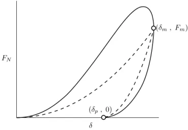
Consider the idealised force-deflection characteristic in Figure 1. The dashed
line conforms to Equation 1 in the loading phase and Equation 5 in the unloading phase: it describes Hertzian contact with permanent indentation. The solid line conforms to Equation 7: it describes Hertzian contact with permanent indentation to which Hunt-Crossley damping has been added in both phases of
the impact. Figure 1
about here If the solid line in Figure 1 represents what has been generated from test data,
the dashed line can be considered to be the elastic component of the contact force, Fe which, with c, needs to be estimated in the model fitting process.
The parametersδp andδm can be determined simply from the experimentally produced force-penetration data.
Consider the loading phase of the impact. Let the estimate forFeandcbe Fe∗ and c∗. As these parameters are to be estimated with reference to F, the measured force during the loading phase can be expressed as
F=Fe∗h
1 +c∗δ˙i
=Fe
h1 +cδ˙i
cmay be thought of as the sum ofc∗and an error in its estimation, ǫ:
c=c∗+ǫ
Now the measured normal force can be re-expressed thus:
F=Fe∗h
1 + (c+ǫ) ˙δi
=Fe
h 1 +cδ˙i
Rearranging:
Fe∗= h
1 +cδ˙i 1 + (c+ǫ) ˙δFe
It is now possible to examine the effect ofǫonFe∗(Figure 2). Whenǫis less than zero, not all the damping is accounted for and so some residual damping will be apparent in the characteristic of Fe∗. This is observed as a decrease in Fe∗ toward the end of the loading phase, which is a sign of rate-dependant damping [14]. This is illustrated by the small-dashed line with a rounded peak in Figure 2. Ifǫis greater than zero, more ofF is being attributed to damping than is realistic and this is observable as an inverted loop inFe∗near the peak of the characteristic such that the unloading phase crosses over the loading phase (the longer dashed line in Figure 2). We therefore have a criterion by which an appropriate value of ccan be estimated: an appropriate estimate for ccan be obtained by choosing a value that produces neither an inverted loop nor a rounded peak in the characteristic of Fe∗ and where the maximum value of
Fe∗occurs atδm∗. Figure 2
about here
If the contact is to be modelled according to Equation 7, curve fitting can be employed to estimate the most appropriate value of the indexn. The value ofK is then
K = Fm
δnm
The resulting characteristicFe∗may be represented more faithfully by an alter- native definition ofFe, rather than Equation 1. In this case the contact can be modelled according to Equation 8.
It should be noted that while Equation 4 is not an appropriate estimator of c, for reasons mentioned previously, a dependence ofcon impact velocity is still to be expected. And so impact tests conducted at different impact speeds may suggest different values forc. Where a single value ofcis preferred, an average value can be used, depending on the degree of accuracy required.
4 Characterisation of example test data
The previous Section described a procedure to fit the model to experimental data. This Section demonstrates the fitting of the model to impact tests con- ducted with the front bumper of a vehicle. The objective in conducting the tests was to characterise each impact with a single contact-impact model in a multibody simulation of each impact.
Two physical impact tests were conducted between an EEVC WG17 upper legform impactor and the bumper of a 2000 vintage Renault Scenic at locations equidistant from the centre-line of the vehicle. The EEVC WG17 upper legform is a guided impactor that is designed to represent the upper leg of an adult pedestrian. It consists of a foam-covered, simply-supported beam mounted to a guidance system. The beam’s dynamic reaction forces are measured during the test.
Data from the tests were processed to produce force-deflection data: force data were compensated to take account of the mass forward of the force trans- ducers and were subsequently converted to acceleration and integrated twice to produce estimates of penetration and penetration velocity of the impactor
during the test. A photograph of the test set up is shown in Figure 3. Figure 3 about here The kinetic energy in the legform was 171 J in Test 1 and 448 J in Test 2.
Dividing the force data by[1 +cδ]˙ produced the curves shown in Figure 4 for a
value ofcequal to 0.15 m-1s. Curve fitting was used to fit a line corresponding Figure 4 about here to Fe = K(δ +γ)n in the loading phase and Fe = Kh
δm
δm−δpδ+γin
in the unloading phase, whereδmandδpwere estimated from the data collected during the higher energy test. The parameterγ was introduced to improve the model
fit in the phasing of the pulse. Its introduction meant that the initial and final conditions had to be additionally prescribed. For the unloading phaseδm and δpwere estimated from Test 2. The values of the parameters in the fitted model wereK= 3300,n= 3.0andγ= 0.021.
These model parameters were implemented in a MADYMO simulation of a cylinder-ellipsoid contact, with initial conditions of each test applied (Figure
5). Elastic loading and unloading curves were created from the fitted model in Figure 5 about here the domain 0< δ≤ δm and δp < δ≤ δm. These curves were specified with a
damping parameter of 0.15 m-1s.
The unloading behaviour in the model was additionally specified by using a hysteresis model in which the unloading curve (which in MADYMO is defined to pass through the origin of the force-deflection axes) is shifted such that it intersects with the loading curve at Fm, thus necessitating a translation by δp.The hysteresis model implies that, whatever the initial impact velocity, the impact will produce an identical elastic unloading curve to any other impact apart from the position of the unloading curve along theδaxis. In other words, the elastic unloading curve of any given impact can be translated along theδ axis to a single curve that passes through the origin. This will only be true if δm/(δm−δp) is constant or, expressed differently, the ratio of the permanent deformation to the maximum penetration is constant. Other allowable hysteresis models in MADYMO imply that, for the Hunt-Crossley model with permanent indentation, eitherδm−δp is constant, orδmn/(δm−δp)is constant.
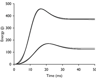
Figures 6 through 8 show the resulting force-deflection curves, the force-time characteristics and the energy-time characteristics, and the equivalent measured in the tests themselves. Impact parameters of each test and the equivalents
estimated by the model are shown in Table 1. Figures 6 to
8 and Table 1 about here
5 Discussion and conclusions
This paper has presented a method of treating experimentally produced impact data to generate an contact-impact model suitable for use in multibody simu- lations. Its advantages include valid treatment of damping, which allows rate effects to be correctly included. It does not suffer from the problems associ- ated with several previous methods of characterising contact-impact properties in pedestrian simulation studies, such as the inability to include rate dependent effects, and/or extrapolation/interpolation to different impact energies [4, 5]
or the inability to include permanent deformation [17, 18]. It is a practica- ble and justifiable method of defining stiffness that is likely to be valid over a wider range of impact conditions than previous contact-impact models used in reported simulations of pedestrian impacts.
By its nature, the method may not be appropriate where significant struc- tural discontinuities affect the force pulse, nor where the elastic wave effects cannot be neglected [24]. However, some of these effects may be included by using a more general form of the contact-impact model given in Equation 8 in limited circumstances.
To demonstrate the method, two EEVC WG17 upper legform impact tests of the same structure at different impact energies were analysed and the proposed contact-impact model was fitted to the resulting data. The tests were then simulated using the multibody simulation software package MADYMO, using the fitted contact-impact model. Only minor discrepancies between the tests and simulations that used the contact-impact model were found, including small details in the shape of the pulse and small errors in the magnitude and timing of certain impact events. Model coefficients of restitution were within 10% of the experimental values. Given the ability of the model to reproduce the impact characteristics of each test, we assume that the contact-impact model is valid within the domain bounded by the impact speeds of both tests.
Regarding the specification of Equation 2, Hunt and Crossley setp =nin order to allow a solution to their analytical formulation of the contact problem and q= 1to allow the damping factor in Equation 3 to be independent of the Hertzian stiffness indexn. Hunt and Crossley’s assumption thatp=nhas been questioned by some [29, 30]. However, the analysis in the present paper adopted the convention used by Hunt and Crossley and used by [19] amongst others, and assumedp=n, insofar that it has proved, in the application to which we have applied it, phenomenologically adequate. It should be noted however, that this decision is based on an observation of adequacy, rather than one grounded in firm theory.
Hertz’s theoretical consideration of the elastic impact of spherical surfaces showed that the theoretical value ofnis3/2[31]. Subsequent theoretical treat- ments of the viscous component of the impact force between colliding spheres suggest that the value of p is equal to 1/2 [32], while experimental results for a sphere contacting a rigid plane have been consistent withp=1/2or1/4[33].
Analysis of the test data presented here produced a Hertzian stiffness index n= 3.0(=p). It should be noted, that consistent with the generalised contact model given by Equation 8, the values of the model parameters in the demon- stration data, including n, are the product of curve fitting, without a priori theoretical constraints on their values. However, the reader should be alert to the limitations of this approach and an extension of the methods described here for cases wherep6=nandq6= 1remains as a future development.
There has been some effort to collect and publish stiffness data for the pur- poses of improving pedestrian impact simulation [16, 15]. The methods de-
scribed herein appear to provide an appropriate method for characterising much of that data in a form suitable for multibody simulations of pedestrian impacts.
It is also likely that the model is applicable in other crash testing simulation areas.
One limitation of MADYMO is that damping must be specified only once for the contact - it cannot be defined separately for each contact surface, and hence this method is restricted to the definition of a combined contact characteristic.
We must therefore assume that the impactor that is used conduct the test is an adequate representation of the human body under impact loads.
6 Acknowledgements
This project was funded through a grant from the Australian Government De- partment of Infrastructure, Transport, Regional Development and Local Gov- ernment, and through sustaining funds received from the Motor Accident Com- mission of South Australia and the South Australian Department for Transport, Energy and Infrastructure.
The author is grateful for the helpful assistance of Andrew van den Berg, Daniel Searson and Samuel Doecke of the Centre for Automotive Safety Re- search, the University of Adelaide.
References
[1] van Rooij, L., Meissner, M., Bhalla, K., Crandall, J., Longhitano, D., Taka- hashi, Y., Dokko, Y., Kikuchi, Y.: The evaluation of the kinematics of the MADYMO human pedestrian model against experimental tests and the in- fluence of a more biofidelic knee joint. Paper presented at the 5th American MADYMO Users’ Meeting, Troy, MI, October 2003
[2] Anderson, R.W.G., McLean, A.J., Ponte, G. , Streeter, L.: Pedestrian re- construction using multibody MADYMO simulation and the POLAR-II dummy: a comparison of head kinematics. In: Proceedings of the 20th In- ternational Technical Conference on the Enhanced Safety of Vehicles, Lyon, France, 18-21 June 2007, National Highway Traffic Safety Administration, Paper 07-0273 (2007)
[3] Simms, C., Wood, D.: Pedestrian risk from cars and sport utility vehicles - a comparative analytical study. Proc. IMechE Part D: J. Automobile Engineering,220(8): 1085–1100 (2006)
[4] Liu, X.J., Yang, J. K., Lövsund, P.: A study of influences of vehicle speed and front structure on pedestrian impact responses using mathematical models. Traffic Injury Prevention,3(1): 31–42 (2002)
[5] van Rooij, L., Bhalla, K., Meissner, M., Ivarsson, J., Crandall, J., Longhi- tano, D., Takahashi, Y., Dokko, Y., Kikuchi, Y.: Pedestrian crash recon- struction using multi-body modeling with geometrically detailed, validated vehicle models and advanced pedestrian injury criteria. In: Proceedings of the 18th International Technical Conference on the Enhanced Safety of Vehicles, Nagoya, Japan, 19-22 May 2003, Paper Number 468 (2003) [6] Anderson, R.W.G., McLean, A.J., Dokko, Y.: Determining accurate con-
tact definitions in multi-body simulations for DOE-type reconstruction of head impacts in pedestrian accidents. In: Proceedings of the 19th Interna- tional Technical Conference on the Enhanced Safety of Vehicles, Washing- ton D.C. 6-9 June 2005, National Highway Traffic Administration, Paper 05-0175 (2005)
[7] Shen., J., Jin, X.-L.: Improvement in numerical reconstruction for vehicle- pedestrian accidents. Proc. IMechE Part D: J. Automobile Engineering, 222(1): 25–39 (2008)
[8] Linder, A., Douglas, C., Clark, A., Fildes, B., Yang, J., Otte, D.: Math- ematical simulations of real-world pedestrian-vehicle collisions. In: Pro- ceedings of the 19th International Technical Conference on the Enhanced
Safety of Vehicles, Washington D.C., 6-9 June 2005, National Highway Traffic Safety Administration, Paper 05-285 (2005)
[9] Longhitano, D., Burke,C., Bean, J., Watts, D., Fakhry, S., Meissner, M., Ivarsson, J., Sherwood, C., Crandall, J., Takahashi, Y., Kadotani, Y., Hitchcock, R., Kinoshita, Y.: Application of the CIREN methodology to the study of pedestrian crash injuries.In: Proceedings of the 19th Interna- tional Technical Conference on the Enhanced Safety of Vehicles, Washing- ton D.C., 6-9 June 2005, National Highway Traffic Safety Administration, Paper 05-0404 (2005)
[10] Stammen, J., Barsan-Anelli, A.: Adaptation of a human body mathemati- cal model to simulation of pedestrian/vehicle interactions. Paper presented at the 4th MADYMO User’s Meeting of The America’s, Detroit, MI, 24 October 2001
[11] Baumgartner, D., Marjoux, D., Willinger, R., Carter, E., Neal-Sturgess, C., Guerra, L., Martinez, L., Hardy, R.: Pedestrian safety enhancement using numerical methods. In: Proceedings of the 20th International Technical Conference on the Enhanced Safety of Vehicles Conference, Lyon, France, 18-21 June 2007, National Highway Traffic Safety Administration, Paper 07-0426 (2007)
[12] Anderson, R.W.G., Streeter, L., Ponte, G., Van de Griend, M., Lindsay, T., Mclean, A.J.: Pedestrian subsystem head impact results reflect the severity of pedestrian head injuries. Int. J. Veh. Des.,31(1/2): 1–15 (2003) [13] Bose, D., Bhalla, L., van Rooij, L., Millington, S., Studley, A., Crandall, J.:
Response of the knee joint to the pedestrian impact loading environment.
SAE Paper Number 2004-01-1608. Society of Automotive Engineers (2004) [14] Lazan, B.J.: Damping of materials and members in structural mechanics.
Pergamon Press Ltd, Oxford, England (1968)
[15] Martinez, L., Guerra, L.J., Ferichola, G., Garcia, A., Yang, J.: Stiffness corridors of the European fleet for pedestrian simulations. In: Proceedings of the 20th International Technical Conference on the Enhanced Safety of Vehicles, Lyon, France, 18-21 June 2007, National Highway Traffic Safety Administration, paper 07–0267 (2007)
[16] Martinez, L., Guerra, L.J., Ferichola, G., Garcia, A., Yang, J., Yao, J.:
Stiffness corridors for the current European fleet. Technical Report AP- SP31-0009R, APROSYS (2006)
[17] Ambrósio, J.A.C.: Vehicle structural impact and occupant biomechanics in a multibody integrated environment. Int. J. Crashworthiness.,4(1): 39–58 (1999)
[18] Silva, M.P.T., Ambrósio, J.A.C.: Pedestrian impact and run over using a multibody simulation tool. Int. J. Crashworthiness.,4(3): 26 –272 (1999) [19] Lankarani, H.M., Nikravesh, P.E.: A contact force model with hysteresis damping for impact analysis of multi-body systems. J. Mech. Des., 112:
369–376 (1990)
[20] Hunt, K.H., Crossley, F.R.: Coefficient of restitution interpreted as damp- ing in vibroimpact. J. Appl. Mech.,42(E):440–445, (1975)
[21] Hu, H., Jin, D.: Identification of impact damping of two elastic bodies. In:
1999 ASME Design Engineering Technical Conference, 2089–2094 (1999) [22] MADYMO Theory Manual version 6.3 . TNO MADYMO BV, Schoemak-
erstraat 97 2628 VK, Delft, The Netherlands (2005)
[23] Kharaz, A.H., Gorham, D.A.: A study of the restitution coefficient in elastic-plastic impact. Philosophical Magazine Letters, 80(8): 549–559 (2000)
[24] Gilardi G., Sharf, I.: Literature survey of contact dynamics modelling.
Mechanism and Machine Theory,37(10): 1213–1239 (2002)
[25] Goldsmith, W.: Impact: The Theory and Physical Behaviour of Colliding Solids. Edward Arnold (1960)
[26] Han, I.: Non-linear continuous-contact-force model for low-speed front-to- rear vehicle impact. Proc. IMechE Part D: J. Automobile Engineering,221:
1197–1208 (2007)
[27] Lankarani, H.M., Deren., M.A., Menon, R.:Multibody dynamics of aircraft occupants seated behind interior walls. Nonlinear Dynamics, 6: 237–246 (1994)
[28] Flores, P., Claro, J.C.P., Ambrósio, J., Lankarani, H.M. Koshy, C.S.: Study of contact-impact force models in multibody mechanical systems. Paper presented at the Tenth Conference on Nonlinear Vibrations, Stability and Dynamics of Structures, 25-28 July 2004, Virginia Polytechnic Institute (2004)
[29] Faik, S., Witteman, H.: Modeling of impact dynamics: a literature survey.
Paper presented at the North American ADAMS User Conference, (2000)
[30] Zamankhan, P., Zamankhan, P., Polashenski, W., Ghazanfari, M.: Tran- sitional granular flow in a spinning bucket at high frequencies. Physica D:
Nonlinear Phenomena,188(1-2): 40–64 (2004).
[31] Hertz, H.: Ueber die Beruehrung elastischer Koerper. Gesammelte Werke, Vol. 1. Leipzig (1895)
[32] Kuwabara, G., Kono, K.:Restitution coefficient in a collision between two spheres. Jap. J. App. Phys.26(8): 1230–1233 (1987)
[33] Falcon, E., Laroche, C., Fauve, S., Coste, C.: Behviour of one elastic ball bouncing repeatdly off the ground. Eur. Phys. J. B,3: 45–57
Figure 1: Loading and unloading conforming to Hertzian contact with perma- nent indentation (dashed line) and Hertzian contact with permanent indentation to which Hunt-Crossley damping has been added in both phases.
Figure 2: The dashed lines show the effect of the error ǫon the estimation of FE (the solid line)
Figure 3: Test set up used to acquire impact data for modelling the impact between the EEVC WG17 upper legform and the bumper of a 2000 Renault Scenic
!
"
#
$
%
%!
&
#
&
%!
'(
)*
+
,-./.012/
3 45678
9:;<
Figure 4: Estimated elastic components of the force-penetration characteristic in Test1 and Test 2 (grey lines) and the fitted characteristic (black line)
Figure 5: MADYMO model of the impact tests
!
"
#
$
%
%!
& ! & " & # & $ &% &%!
'
()(*+,*-.
)/ 0 1 23456
789:
Figure 6: Force-penetration characteristics in Test1 and Test 2 (grey lines) and characteristics produced by the simulation (black line)
!
"
#
$
%
% ! & " '
()
*+, *- . /0123
4567
Figure 7: Force-time data from Test1 and Test 2 (grey lines) and pulses produced by the simulation (black lines)
8 98 8 :8 8
;8 8
<8 8
=8 8
8 98 :8 ;8 <8 =8
>?
@A B @C
D EFGHIJ
KLM
Figure 8: Contact energy-time data from the contacts in Test1 and Test 2 (grey lines) and that which was produced by the simulation (black lines)
Table 1: Summary of the comparison between the test data and the MADYMO implementation of the contact impact model
Parameter Test 1 Test 2
Test Model Test Model
Impact energy 171 J 458 J
Peak force 4.57 kN 4.70 kN 9.57 kN 9.66 kN Timing of peak force 18.7 ms 18.4 ms 12.0 ms 13.3 ms Timing of peak energy absorbed 21.5 ms 22.4 ms 16.4 ms 17.4 ms Coefficient of restitution 0.47 0.52 0.44 0.43
Title: Continuous contact-impact modelling for multi-body simulations of pedestrian-vehicle contact interactions based on experimental data
Running title: Contact-impact modelling of pedestrian-vehicle impacts Author: Robert W. G. Anderson, Alexandra D. Long and Thierry Serre Affliation and Address (Anderson and Long): Centre for Automotive Safety Research, University of Adelaide, South Australia, 5005, AUSTRALIA
Telephone: +61 8 8303 5888 Fax: +61 8 8232 4995
E-mail: robert@casr.adelaide.edu.au
Affliation and Address (Serre): Laboratoire de Biomécanique Appliquée - UMRT24 INRETS (Institut National de Recherche sur les Transports et leur Sécurité) Université de la Méditerranée Faculté de Médecine - Secteur Nord Boulevard P. Dramard 13916 Marseille Cedex 20 FRANCE
Manuscript
Click here to download Manuscript: Anderson et al revised.dvi Click here to view linked References