HAL Id: hal-01068035
https://hal.archives-ouvertes.fr/hal-01068035
Submitted on 24 Sep 2014
HAL is a multi-disciplinary open access archive for the deposit and dissemination of sci- entific research documents, whether they are pub- lished or not. The documents may come from
L’archive ouverte pluridisciplinaire HAL, est destinée au dépôt et à la diffusion de documents scientifiques de niveau recherche, publiés ou non, émanant des établissements d’enseignement et de
In-plane mechanics of soft architectured fibre-reinforced silicone rubber membranes
Lucie Bailly, Mamadou Toungara, Laurent Orgéas, Eric Bertrand, Valérie Deplano, Christian Geindreau
To cite this version:
Lucie Bailly, Mamadou Toungara, Laurent Orgéas, Eric Bertrand, Valérie Deplano, et al.. In-plane mechanics of soft architectured fibre-reinforced silicone rubber membranes. Journal of the mechanical behavior of biomedical materials, Elsevier, 2014, 40, pp.339-353. �10.1016/j.jmbbm.2014.09.012�. �hal- 01068035�
Author's Accepted Manuscript
In-plane mechanics of soft architectured fibre-reinforced silicone rubber mem- branes
L. Bailly, M. Toungara, L. Orgéas, E. Bertrand, V. Deplano, C. Geindreau
PII: S1751-6161(14)00296-3
DOI: http://dx.doi.org/10.1016/j.jmbbm.2014.09.012 Reference: JMBBM1270
To appear in: Journal of the Mechanical Behavior of Biomedical Materials Received date:26 June 2014
Revised date: 1 September 2014 Accepted date:
8 September 2014
Cite this article as: L. Bailly, M. Toungara, L. Orgéas, E. Bertrand, V.
Deplano, C. Geindreau, In-plane mechanics of soft architectured fibre- reinforced silicone rubber membranes, Journal of the Mechanical Behavior of Biomedical Materials, http://dx.doi.org/10.1016/j.jmbbm.2014.09.012
This is a PDF file of an unedited manuscript that has been accepted for publication. As a service to our customers we are providing this early version of the manuscript. The manuscript will undergo copyediting, typesetting, and review of the resulting galley proof before it is published in its final citable form. Please note that during the production process errors may be discovered which could affect the content, and all legal disclaimers that apply to the journal pertain.
www.elsevier.com/locate/jmbbm
In-plane mechanics of soft architectured fibre-reinforced silicone rubber membranes
L. Bailly
a,∗ , M. Toungara
b,c, L. Org´ eas
b,c, E. Bertrand
aV. Deplano
aand C. Geindreau
b,caAix Marseille Universit´e, CNRS, Centrale Marseille, IRPHE UMR 7342, 13384,
Marseille, France
bUniv. Grenoble Alpes, 3SR Lab, F-38000 Grenoble, France
cCNRS, 3SR Lab, F-38000 Grenoble, France
Abstract
Silicone rubber membranes reinforced with architectured fibre networks were pro- cessed with a dedicated apparatus, allowing a control of the fibre content and ori- entation. The membranes were subjected to tensile loadings combined with con- tinuous and discrete kinematical field measurements (DIC and particle tracking).
These tests show that the mechanical behaviour of the membranes is hyperelastic at the first order. They highlight the influence of the fibre content and orientation on both the membrane in-plane deformation and stress levels. They also prove that for the considered fibrous architectures and mechanical loadings, the motion and deformation of fibres is an affine function of the macroscale transformation. These trends are fairly well described by the micromechanical model proposed recently in Bailly et al. (JMBBM, 2012). This result proves that these materials are very good candidates for new biomimetic membranes, e.g. to improve aortic analogues used forin vitro experiments, or existing textiles used for vascular (endo)prostheses.
Key words: Micro-mechanical model, Tensile tests, Biomimetism, Fibre-reinforced membrane, Anisotropy, Material design, Silicone rubber
∗ Corresponding author. Phone: +33 (0)4 13 55 20 27. Address: IRPHE, Technopˆole de Chˆateau Gombert, 49, rue F. Joliot Curie B.P. 146, 13384 Marseille Cedex 13, France.
Email address: lucie.bailly@irphe.univ-mrs.fr(L. Bailly).
1 Introduction
Human abdominal aortic tissue (AA) is a complex soft sandwich structure, arranged in three different layers. Within these layers, the distribution of all components dis- plays a double-helix architecture of collagen fibres, elastic fibres, smooth muscle cells and other molecules of the extracellular matrix (Holzapfel, 2008). The fibrous microstructure is characterised by a particular wavy arrangement under stress-free conditions (Freed and Doehring, 2005; Holzapfel, 2008; Rezakhaniha et al., 2011) and by distinctive preferred orientations when subjected to a mechanical loading (Holzapfel, 2006; Horny et al., 2010). These histological features provide the ab- dominal aortic tissue a highly non-linear, anisotropic and essentially hyperelastic mechanical behaviour (Vande Geestet al., 2006). Over the past decades, several syn- thetic materials aiming at mimicking the microstructural and/or mechanical speci- ficities of aortic tissue were developed (i) to perform in vitro experiments, or (ii) for bioengineering issues:
(i) In vitro experiments were carried out to characterise biomechanical factors in- volved in the evolution of arterial diseases such as Abdominal Aortic Aneurysm (AAA). For that purpose, several deformable AAA analogues were processed. Most of them were placed into vascular flow simulators to investigate endovascular repair (Schurink et al., 1998; Flora et al., 2002; Chong and How, 2004; Gawenda et al., 2004). Few were utilised to quantify biological fluid-structure interactions within AAAs (Eneet al., 2011; Deplano et al., 2013, 2014). Inflation tests were conducted by increasing internal pressure in order to identify AAAs deformation or rupture locations (Morris et al., 2004; Doyle et al., 2009, 2010; Corbett et al., 2010; Meyer et al., 2011). However, all these materials were made up of homogeneous elastomers with isotropic material properties, which are very far from the anisotropic hypere- lastic behaviour of aortic tissue and from its fibrous microstructure.
(ii) In parallel, in the field of vascular tissue engineering, numerous implants were
designed so as to be mechanically as close as possible to the host tissue macroscale mechanical behaviour. To this end, polymeric fibrous composites were largely de- signed as bioinspired scaffolds (Li and Cooper Jr, 2011). Various manufacturing processes were also developed to elaborate fibrous networks (Ratcliffe, 2000; Chen and Hunt, 2007). Currently, a specific interest is provided to fibre electrospinning and textile processing techniques:
(a) Electrospinning technology is favoured to manufacture nano-structured bioma- terials made up of filaments close to collagen/elastin fibrils dimensions (Matthews et al., 2002; Bolandet al., 2004; Agarwalet al., 2008; Clureet al., 2010). Recent advances allow a better control of the electrospun fibres morphology, strength and size by adjusting set-up conditions or polymer solution parameters (Kowal- czyk et al., 2008; Soliman et al., 2011). However, the control of the fibres po- sition and orientation is still a challenging task to generate the desired macro- scopic mechanical anisotropy (Bu et al., 2012).
(b) Textile processing techniques are also widely used to develop vascular (endo)prostheses (Jacobs et al., 2003; Chakfe et al., 2004; VanLieshout et al., 2006). Knitted, braided or woven fabrics are characterised by a fine regular arrangement of the fibres, therefore allowing a better control of the macroscopic anisotropic properties (Xu et al., 2010; Schreiber et al., 2010; Yang et al., 2012). However, due to their inappropriate fibrous microstructures, the current commercial tex- tile prostheses do not exhibit suitable deformability (Surovtsova, 2005; Sarkar et al., 2006; Demanget et al., 2012, 2013; Lemercier et al., 2013).
Therefore, the global objective of this work is to design and process new artificial ma- terials, able to mimic the macroscopic anisotropic properties of AA and AAA tissues, their hyperelastic J-shape mechanical response, and their main histological features (fibrous microstructures with distinctive fibre orientations). In the short run, these materials represent appropriate candidates to perform in vitro experiments similar to those carried out in Deplano et al. (2014), with more relevant models of AAs or
AAAs. In the long run, they could help improving the design of aortic prostheses towards more efficient mechanical performances. To this end, optimal elastomeric fibrous composites were identified in a previous theoretical work using a multi-scale homogenisation process combined with microstructure optimisation (Bailly et al., 2012). The optimised architectured materials are composed of a thin and soft hy- perelastic membrane reinforced by periodic fibrous lattices displaying four preferred orientations and hyperelastic fibres. The present study aims at (i) providing exper- imental advances concerning the manufacturing and mechanical characterisation of such architectured soft fibre-reinforced membranes, and (ii) validating the assump- tions stated to build the micro-mechanical model in Bailly et al. (2012). Thus, a summary of the theoretical background is first reported in Section 2. The manufac- turing processes of the elastomeric fibrous membranes are presented in Section 3, along with the method used to characterise their mechanical behaviour. Experimen- tal results are detailed in Section 4. A comparison between these results and the prediction of the micromechanical model is proposed and discussed in Section 5.
2 Theoretical background
To mimic the main histological features of the arterial tissues, various fibrous ar- chitectures were investigated with the micro-mechanical model proposed in Bailly et al. (2012), i.e. single or bi-layers lattices of fibres. As a first step in the valida- tion of the model assumptions, the present study focuses on the one-layer fibrous structure, as illustrated in Figure 1(a). This structure comprises a single lattice of crossed, identical continuous and straight fibres of initial cross-section S0, embed- ded into a thin and soft elastomer matrix. Each fibrous lattice can be seen as a repetition of a Representative Elementary Cell (REC) lying in the (ex,ey) plane, as sketched in Figure 1(b) in the initial configuration C0. The microscale geometrical and mechanical assumptions related to the REC are summarised as follows:
(i) The REC geometry is characterised by two periodic vectorsP1 =A1A4 =0E1 andP2 =A1A2 =0E2(resp.p1 =a1a4 =1e1 andp2 =a1a2 =2e2) joining the extremities A1, A2 and A4 (resp. a1, a2 and a4) of the REC in the initial C0 (resp. deformed C) configuration. The angles (ex,P1) and (ex,P2) [resp.
(ex,p1) and (ex,p2)] are noted θ01 and θ02 (resp. θ1 and θ2) inC0 (resp. in C).
Initial REC configuration is defined so that: θ02=−θ01=θ0.
(ii) Fibres are supposed to be linked at the REC extremities A1, A2, A3 and A4, in such a way that the relative displacement of fibres at these points is zero.
Between these points, the initial and deformed lengths of fibre i (i = 1 and 2) are expressed asf0i =||Pi||=0 andfi =||pi||=i, respectively. Furthermore, its elongation λfi and its tension tfi are expressed asλfi =i/0 and tfi =tfiei (no summation on the indexi). Fibres are assumed to behave as hyperelastic bars, i.e. the tensions tfi only depend on the fibre elongations λfi via a fibre strain energy function Wf.
(iii) The mechanical interactions between the fibres lattice and the homogeneous elastomer membrane, and between the fibres are negligible.
The macroscale mechanical behaviour of such periodic fibrous lattice was entirely determined analytically, by using the homogenisation of periodic discrete structures (Caillerieet al., 2006; Baillyet al., 2012). It was shown that the overall macroscopic Cauchy tension tensor τc of the one-layer fibrous membrane can be written as:
τc=τm+ 1
||p1 ×p2||
2 i=1
(tfi⊗pi), (1)
whereτm corresponds to the Cauchy tension tensor of the elastomer membrane con- tribution. Thus, knowing the mechanical behaviour of the elastomeric membrane, that of the fibres, and the geometry of the REC, the mechanical behaviour of the considered architectured and fibre-reinforced membranes is fully estimated: no con- stitutive parameter has to be fitted a posteriori.
3 Experimental procedure
3.1 Materials
Matrix - A biocompatible high strength RTV Silicone elastomer dispersion (PN 40021, Applied Silicone Corporation) was selected as matrix material, due to its high deformability and specific physical properties. It allowed an easy impregnation of the fibrous network and cured at room-temperature. To minimise the scattering of the experimental results, a particular attention was brought to subject the processed membranes to the same curing time (24h) and to keep them at the same room temperature (290K) and relative humidity (50%) until mechanical testing.
The silicone in-plane mechanical response was investigated by means of a uniaxial tensile-testing device (Bose Corporation, Eden Prairie, Minnesota) equipped with a load cell of capacity of 450±0.01 N. Displacement-controlled tests were performed at room temperature on 8 rectangular samples of mean initial gauge L0 = 21.21 mm (STD = 1.07 mm), width W0 = 10.13 mm (STD = 0.47 mm) and thickness T0
= 1.05 mm (STD = 0.22mm), STD being the data standard deviation. Note that these dimensions were determined by photographing the undeformed samples with an accuracy of 0.02 mm. Each sample was subjected to 10 load-unload cycles, with a maximal tensile elongation of 1.30 and an elongation rate of 10−2 s−1, representative of AA tissue’s physiological loadings (Bailly et al., 2014). During the tests, pictures of the sample’s gauge zone were recorded with a JAI CCD camera (1624 × 1236 pixels, 25 Hz). Before, speckles were drawn on the surface of each strip so that strain field measurements could be carried out using 2D Digital Image Correlation (DIC), as illustrated in Figure 1(d). Elongations of the specimen along the stretch ey and the transversal ex directions, i.e. respectively λyy and λxx, were calculated using a DIC software (7D) developed by Vacheret al.(1999). Longitudinal forceFy was also measured during the tests and corresponding component of the first Piola-Kirchhoff
stress tensor was defined as Πyy =Fy/W0T0.
Typical experimental data are displayed in Figure 1(d), showing both the elongation path (λxx, λyy) and the stress-elongation response (Πyy, λyy). A low hysteresis was measured during the load/unload sequences. Therefore, as a first reasonable approxi- mation, it can be inferred that the considered silicone rubber behaved nearly as a hy- perelastic material. Besides, within the investigated elongation range, its mechanical behaviour could be fairly well modelled with a classical neo-Hookean model (Treloar, 1943), thus characterised by a volumetric strain-energy functionWm =cm(I1−3)/2.
The constant cm is a positive material parameter, and I1 = tr(C) denotes the first principal invariant of the right Cauchy-Green tensor C. This model was adjusted on both curves, as illustrated in Figure 1(d). For all samples, the average material parameter was found aroundcm= 0.24 MPa (STD = 0.01 MPa).
Fibre- A 50μm diameter polyamid monofilament was selected as a fibre candidate.
This fibre is commonly used as fishing wire (Feeling 36605, Sensas - 0.8 lb, 0.350 kg).
Uniaxial tensile tests were performed to characterise the mechanical behaviour of 16 fibre samples cut from this filament on a dedicated testing machine (Instron 3367, 100 ± 0.01 N). Tests were conducted until failure, using an elongation rate of 10−2 s−1, and an initial fibre length of 200 mm at rest. The force within each fibre sample tf was measured during the tests and the corresponding first Piola-Kirchhoff stress was estimated as Πf = tf/S0, S0 being the fibre unloaded cross-section. Figure 1(e) presents the mean stress value Πf, as function of fibre elongation λf, measured in average over the 16 samples. The obtained fibre mechanical behaviour is repeatable and non-linear. Failure loads varied from 1.93 to 2.35 N (mean value 2.21 N), and failure stretches ranged between 1.20 and 1.30 (mean value 1.26). Finally, the exper- imental data could be described by a hyperelastic model proposed in Org´eas et al.
(1998) for Shape Memory Alloys (see Figure 1(e)), so that the mean tension within the fibre is expressed as:
tf= S0
λf
⎧⎪
⎪⎪
⎪⎪
⎪⎪
⎨
⎪⎪
⎪⎪
⎪⎪
⎪⎩
μ1
2
f+ sgn{s−[f+ sgns]2+α21} + sgnσ0
+μ2f +μ23
f+ sgn{[f−sgnc]2+α22−2c +α22} ,
(2)
with s= α21−(2σ0/μ1)2
4σ0/μ1 and sgn =
⎧⎪
⎪⎨
⎪⎪
⎩
1 if f≥0
−1 if f<0.
This tension is a function of the logarithmic strain, f = lnλf, and of 7 constitutive parameters: μ1, μ2, μ3, σ0, c, α1 and α2 (Org´eas, 1997). The model parameters were identified from the experimental data given in Figure 1(e) over the stretch rangeλf∈[1 : 1.15]. The latter covers the range of tensile loadings predicted within the fibres in the experiments below. The identification yielded to μ1 = 2444.94 MPa, μ2 = 223.16 MPa, μ3 = 38652.62 MPa, σ0 = 42.18 MPa, c = 16.25×10⁻², α1 = 9.64×10⁻³ and α2 = 5.20×10⁻².
3.2 Architectured soft fibre-reinforced membranes
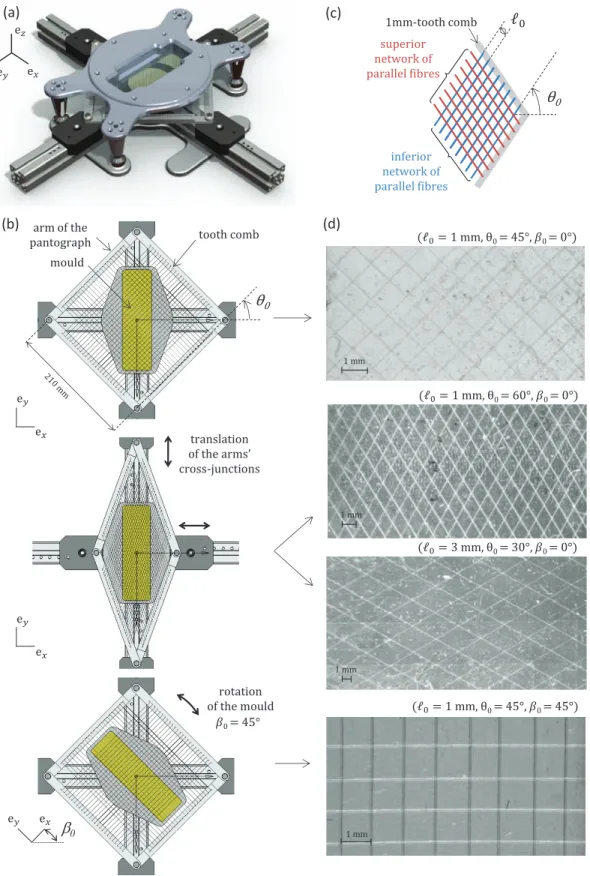
Processing route- The as-described fibre and matrix materials were used to man- ufacture the target fibre-reinforced membranes. For that purpose, a specific device was designed to manufacture lattices of crossed and identical straight fibres, impreg- nated inside rectangular membranes (160 mm × 50 mm), as shown in Figure 2(a).
The device consists of a pantographic deployable structure and a TeflonTM rectan- gular mould. Each arm of the pantograph is equipped with a 1 mm-tooth comb.
Three parameters of the device were adjusted before each composite membrane’s elaboration:
(i) the number of teeth involved in the manufacturing (see Figure 2(c)). This pa- rameter allows the control of the initial fibre length of the lattice, 0, and thus,
the fibre content. Length0 can vary by step of 1 mm.
(ii) the angulation of the pantograph, adjustable by translation of the arm’s cross- junctions as illustrated in Figure 2(b). This parameter allows the control of the initial half-angle between fibres, θ0. It can be varied between 20◦ and 70◦ by step of 5◦.
(iii) the angleβ0 as defined in Figure 2(c), adjustable by rotation of the mould. This parameter allows to control the orientation of the fibre network in the (ex,ey) plane. Two cases were investigated: β0 ={0◦,45◦}.
At a chosen configuration (0, θ0, β0), a first unidirectional fibre network was built using the same fibre. The fibre was guided alternatively by two combs of the pan- tograph facing to each other. In the same way, a second unidirectional network was built using the other combs of the device, and superimposed on the first one. So as to create a 1 mm-thick membrane, the lattice was then embedded by a 20 m-layer of silicone casted into the mould. Note that the depth of the mould was designed (i) to account for the average mass loss (58%) measured after the silicone curing due to solvent evaporation and shrinkage of the silicone during curing, and (ii) to spatially equilibrate the microstructure along the membrane’s thickness. Finally, several composite membranes were processed, characterised by six microstructural arrangements (0, θ0) as follows: (1 mm, 45◦), (3 mm, 45◦), (1 mm, 30◦), (3 mm, 30◦), (1 mm, 60◦), (3 mm, 60◦). These target values of both parameters were chosen in line with previous predictions found in Bailly et al. (2012). Typical illustrations of manufactured microstructures are presented in Figure 2(d).
Samples - Eight rectangular strips (Si,i∈[1, . . . , 8]) were cut from the composite membranes. Their geometrical dimensions were determined so as to preserve the same separation scale from a given sample to another one, by considering 6 RECs along the width and 9 RECs along the length. Strip’s initial dimensions were opti- cally measured and summarised in Table 1. In the following, for the sake of clarity, the composite stripSi, characterised by the triplet of parameters (0,θ0,β0), will be
denoted as Si(0, θ0, β0). In practice, the values of (0, θ0) slightly differed from the target ones. Thus, optical measurements were processed using a particle-tracking method applied on strips’ images registered at rest. The image processing was based on the tracking of experimental REC extremities, as illustrated in Figure 3 upon one REC. For each strip, the measured values of (0, θ0) were averaged on all the surface’s RECs and noted (0, θ0). Values of (0, θ0) are detailed in Table 1. The accuracy of the tracking method was assessed at (0.05 mm, 0.2◦). Finally, the target values of (0, θ0) were achieved within a mean precision of (0.07± 0.05 mm, 0.4 ± 0.2 ◦) over the whole database.
Tensile tests - The in-plane mechanical response of the Si samples was investi- gated using the tensile-testing device and the protocol previously described for the homogeneous membrane. The stretch direction was defined by the vector ey. Thus, for β0 = 0◦, the stretch direction matches the REC diagonal (A4A2 direction). For β0 = 45◦, the stretch direction matches the fibres one, as illustrated in Figure 3.
Each test was repeated twice in order to ensure its reproducibility, and coupled with image recording of the deformed strip. In the following, focus is given to the first load of each test only. The discrete kinematical field measured at the fibre scale was derived from the tracking of experimental REC nodes Ai on each image, as displayed in Figure 3. The image processing was repeated three times on four centered RECs for each composite sample. This yielded to average values of the microscopic longitudinal and transversal elongations, i.e. λyy and λxx respectively.
The local value of the half-angle between the fibres was also derived. This angle was noted θ0 and its evolution was calculated along the test. In summary, for each strip Si, Table 2 compares (i) the target value of angleθ0, (ii) the angle θ0 averaged over all surface’s RECs, and (iii) the angle θ0 averaged over the four RECs associate to the measured elongations (λxx, λyy).
Finally, some samples’ surfaces were additionally covered by speckles to perform 2D DIC measurements. In that case, the continuous kinematical field applied on the
composite membrane was derived in average over a whole REC. Therefore, kinemat- ics measured at the composite scale (global, DIC measurements) and at the fibre scale (local, particle tracking measurements) could be compared.
4 Experimental results on composite membranes
4.1 General trends
Typical measurements are reported in Figure 3, showing the local loading paths (λxx, λyy), the derived local half-angle between the fibres θ as a function of the elongation λyy, and the corresponding tension-elongation response in the composite membrane (τyy, λyy). Two tests repeated on samples S1(1, 45, 0) and S2(1, 45, 45) are illustrated, highlighting important general features:
• whatever the loading angle β0, the repeatability of each test is ensured.
• the local kinematical fields are optically measurable, with an accuracy on angle θbeing of 0.2◦. During the tests, a typical quasi-linear θ-variation is observed
for β0 = 0◦, against zero θ-variation for β0 = 45◦ (see second row in Figure 3).
This angle variation comes up to 15◦ at the applied maximal strain whenβ0 = 0◦. Note that for each sample, a slight change in the value of initial angleθ0 (± 1/2◦) is observed between the first test and the second one: this is probably due to possible fibrous rearrangement (e.g. slight rotation of the fibres due to the low hysteresis measured after loading cycles) or local variations in the sample’s architecture (see Table 2).
• the mechanical effects of the fibrous reinforcement are highly dependent on the loading direction. Forβ0 = 0◦, the fibres progressively align with the stretch di- rection (see pictures in Figure 3(a)). Hence, the lattice mechanical contribution combines the rotations of the fibres with their tensile response. These mecha- nisms typically yield to a drastic contraction of the sample along the transverse
direction (up to λxx = 0.7), and low values of the mechanical tension in the overall membrane at λyy = 1.3 (maximum value of τyy below 0.5 N/mm). On the contrary, for β0 = 45◦, the fibres arranged perpendicular to the stretch di- rection are slightly compressed. They strongly restrain the membrane width’s contraction along the transverse direction (λxx >0.97 during the test). In that case, only the fibres aligned with the loading direction contribute to the overall mechanical tension measured in the composite membrane. Therefore, as the silicone rubber matrix displays soft mechanical properties, the lattice mechan- ical contribution at the macroscale is nearly equivalent to the composite’s one.
The lattice contribution also comes to the tensile response of individual fibre, weighted by the volume fraction of the fibres parallel to the loading direction, vf. This volume fraction is defined by the ratio of the volume of fibres parallel to the loading direction within one REC in configurationC0 (πd200/4), over the volume of the REC (T020sin(2θ0)). This ratio yields to vf = 4T πd20
00sin(2θ0), i.e.
0.2% for S2(1, 45, 45).
4.2 Comparison between global and local kinematics
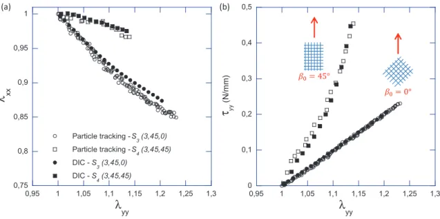
Figure 4(a) confronts the global kinematics measured at the composite scale by 2D DIC, with the local kinematics measured at the fibre scale by tracking the displace- ments of the REC nodesAi. Samples S3(3, 45, 0) andS4(3, 45, 45) were chosen for illustration. Whatever the loading direction, a fairly good quantitative agreement was measured between global and local kinematics, as shown by the superimposition of the loading paths derived from both techniques in Figure 4(a). In particular, the relative differenceer between a couple of stretches determined by DIC (λDICxx , λDICyy ), and the one determined by particle tracking (λtxx, λtyy) was calculated using:
er = [(λDICxx −λtxx)2+ (λDICyy −λtyy)2]0.5
[(λtxx−1)2+ (λtyy−1)2]0.5 (3)
Regarding data series with β0 = 45◦, the average value, er, comes to 13.8% for λyy ∈ [1 : 1.14], and drops down to 6% for λyy > 1.05. Regarding data series with β0 = 0◦, er comes to 17.7% for λyy ∈ [1 : 1.23]. It falls below 15% for λyy > 1.05.
Note that this quantitative agreement is nearly unchanged when calculating the global kinematical field in average over a surface of 3×4 RECs (not shown). From these results, the overall membrane and the REC were considered to be subjected to the same macroscopic transformation gradient (see the discussion below). In the following, the discussed loading paths (λxx, λyy) refer exclusively to the elongations calculated at the fibre scale.
4.3 Influence of the loading angle β0
The graphs of Figure 5(a) compare the loading paths and the Cauchy tension- elongation responses measured on three samples: the isotropic homogeneous silicone membrane, samplesS1(1, 45, 0) and S2(1, 45, 45). All samples are characterised by a similar initial thickness (relative STD being 6.7 %), which enables a comparison relying on tension curves.
Both the mechanical structural reinforcement and the anisotropy induced by the fibrous lattice are emphasised in the left graph of Figure 5(a). For the silicone mem- brane, the shrinkage of the sample width is about 10% at λyy = 1.25. For compos- ite S1(1, 45, 0), the progressive alignment of the fibres along the loading direction favours the sample contraction along thex-direction, and yields to a width-shrinkage of about 30% at λyy = 1.25. On the contrary, for sample S2(1, 45, 45), the width’s decrease is restrained to about 2% beyond λyy = 1.05.
The anisotropy is also highlighted in the right graph of Figure 5(a), showing a global stiffening of the mechanical behaviour induced by the fibrous lattice. The more the fibres are aligned along the stretch direction, the higher the stiffness of the sample and stress levels. A tangent modulus was assessed at a tension value typically
measured in aortic tissue for tensile loadings (Vande Geest et al., 2006; Baillyet al., 2012), i.e. τyy = 0.1 N/mm. The stiffening was characterised by a modulus of 1.13 N/mm for S1(1, 45, 0) [resp. 19.76 N/mm for S2(1, 45, 45)], thus increased by a ratio 1.3 (resp. 22.5) in comparison to the silicone case (0.88 N/mm). At last, the mechanical responses of the silicone and the sample S1(1, 45, 0) were initially superimposed. This suggests that, for this fibrous architecture, i.e. for β0 = 0◦ and for values of θ0 below 45◦, the contribution of the lattice is negligible, at least for λyy <1.05.
4.4 Influence of the initial fibre length 0
The graphs of Figure 5(b) compare the loading paths and the tension-elongation responses measured on five samples of comparable initial thickness (relative STD being 13.7 %): the silicone membrane, samples S1(1, 45, 0), S2(1, 45, 45), S3(3, 45, 0) and S4(3, 45, 45). The influence of initial fibre length 0 can be assessed by comparing the mechanical response of S1(1, 45, 0) and S3(3, 45, 0), and that of S2(1, 45, 45) and S4(3, 45, 45).
Regarding the elongation paths shown in Figure 5(b), the influence of the initial fibre length is noticeable when the loading direction is not aligned with the fibres ones.
Indeed, forβ0 = 0◦, the contraction of the sample initial width (15% forλyy = 1.25) is twice lower for 0 = 3 mm than that observed for 0 = 1 mm. By contrast, for β0 = 45◦, the impact of fibre length 0 on the sample contraction is negligible.
Regarding the tension-elongation responses shown in Figure 5(b), all composites exhibit a global stiffening as compared to the silicone membrane, except for case S3(3, 45, 0). The similarity between the responses of S3(3, 45, 0) and the silicone is mainly ascribed to the differences in thickness samples (ratio of values being 0.76). This similarity disappears when tension data are converted into first Piola- Kirchhoff stresses (not shown). For a given stretch direction β0, the samples with
higher volume fraction of fibres (i.e. for 0 = 1 mm) are stiffer. In particular, the ratio of the tensions achieved forS4(3, 45, 45)by the ones obtained forS2(1, 45, 45) varies between 0.20 and 0.41, around a mean value of 0.36. Beyond low elongations (λyy > 1.03), this ratio rises up to 0.39 in average. This value comes close to the ratio of the volume fractions of the fibres parallel to the loading direction within each sample (i.e. 0.40).
4.5 Influence of the initial half-angle between fibres θ0
The graphs plotted in Figure 5(c) compare the loading paths and the tension- elongation responses measured on five samples of similar initial thickness (relative STD being 8.2 %) for various values of θ0. All composite samples are characterised by an identical initial fibre length (0 = 1 mm) and the same loading direction (β0 = 0◦).
Forθ0 = 30◦, the decrease of the sample’s width is very close to the one of the matrix alone, as shown in the left graph of Figure 5(c). Tension-elongation responses are also rather similar. These results imply that, for such lattice architectures and such elongation range, the fibres are not loaded and they weakly disturb the deformation of the silicone.
By contrast, forθ0 = 60◦, the fibres tend to align along the loading direction as soon asλyy >1. Therefore, the reduction of the sample width is much higher than in the previous case (θ0 = 30◦):λxx = 0.68 versus λxx = 0.90 for λyy = 1.25. Furthermore, the elongation paths being similar for cases θ0 = 45◦ and θ0 = 60◦, the influence of the fibres’ initial orientation is clearly demonstrated on the corresponding tension- elongation responses. The more the fibres are aligned along the stretch direction, the higher the stiffness of the sample.
Note that above results are consistent with those obtained by comparing samples
S3(3, 45, 0),S7(3, 60, 0)andS8(3, 30, 0)exhibiting a larger initial fibre length,0 = 3 mm (see Figure 6). In particular, the low tension-elongation response measured for S8(3, 30, 0) is linked with the small thickness of the sample as compared to the matrix (ratio of values being 0.67,i.e. the lowest in the database).
5 Validation of the micro-mechanical model
5.1 Relevance of some of the model assumptions
As detailed in sections 2 and 3, some major microscale geometrical and mechanical assumptions were formulated in order to apply the micro-mechanical model. Sev- eral experimental observations gained from results shown in section 4 ensure the relevance of these assumptions:
(i) For the tensile loadings under study, the REC geometry is assumed to be diamond-shaped in the initial (resp. actual) configuration C0 (resp. C). Be- sides, the displacements of nodes Ai are assumed to be affine functions of the macroscale gradient of the geometrical transformation the samples are sub- jected to.
The tracking of the experimental RECs extremities showed that their diamond pattern remained topologically unaffected by the transformation (see Figure 3).
Besides, Figure 4 also proved that the motion of nodes Ai were identical to the displacement field recorded at the macroscale with the DIC technique. These observations thus validate above assumptions.
(ii) The fibre mechanical behaviour is predicted by a hyperelastic model (Eq. 2), adjusted on experimental tensile tests performed on fibres (Figure 1(d)). This model assumes a symmetrical behaviour under compressive loading.
It was shown that the fibres are subjected to compressive loading for cases
withβ0 = 45◦. No buckling effect was observed during the considered tests (be- cause the compressive strains remained small and because compressed fibres are confined within the matrix). Thus, the above assumption is reasonable for the considered configurations.
(iii) Finally, the mechanical interactions between the fibres and the matrix, and between the fibres forming the lattice are assumed negligible. Therefore, at the first order, the tension decomposition in Eq. (1) can be considered as a reasonable approximation of the membrane mechanics.
The relevance of this last assumption is detailed in the following.
5.2 Comparison between experimental data and theoretical predictions
Theoretical predictions derived from Eq. (1) were confronted to the experimental results presented in section 4, and displayed along in Figures 5 and 6. All these pre- dictions were calculated by prescribing the experimental elongation paths (λxx, λyy) as input loadings, instead of using an additional assumption of simple tensile test conditions. Note that each plotted experimental elongation path was associated to a local value of the initial half-angle between fibres, θ0 (see bold values in Table 2).
Therefore, in the following, the comparison between experiments and predictions is focused on the Cauchy tension - elongation curves (τyy, λyy).
Over the whole database, whatever the considered triplet of parameters (0,θ0,β0), Figures 5 and 6 demonstrate that the micro-mechanical model predictions fairly well fit the experimental data (cases of discrepancies observed in the database are detailed thereafter). This result is obtained despite the model simplicity and bearing in mind that none arbitrary macroscale adjustment was made a posteriori, i.e. all the model data were acquired at the microscale (the REC scale). In particular, the model is able to predict very precisely the mechanical behaviour of compositesS1(1, 45, 0), S3(1, 45, 0) and S6(1, 30, 0). The average relative difference between data
and predicted tensions is equal to 5.8%, 9.5% and 9.7% respectively. This mean difference remains below 20% for most other composites, with a value of 11.7% for S2(1, 45, 45), 16.4% for S4(3, 45, 45), 18.7% for S7(3, 60, 0) and 15.8% for S8(3, 30, 0). Note that this quantitative agreement between predictions and experimental data is similar when considering the second local value ofθ0 in Table 2 (not shown).
Such a good accordance validates model assumption (iii).
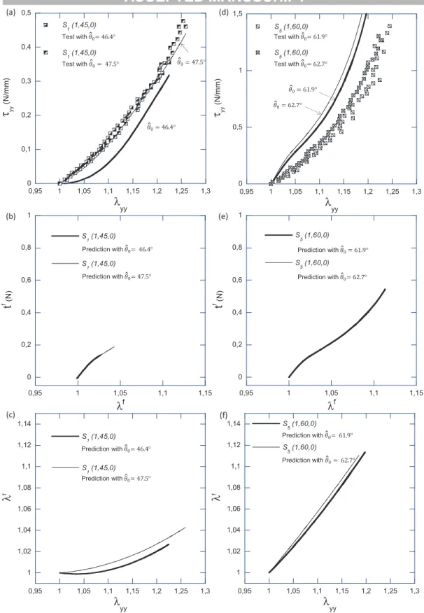
However, some discrepancies can be observed in two particular cases:
• the first case is pointed out in Figure 7(a). Two tests were performed on sam- ple S1(1, 45, 0), with a good repeatability in both loading path and tension- elongation curves (see Figure 3(a)). The unique input difference between both test conditions relied on the applied experimental path and the associate value of initial angle θ0, as measured to determine the local kinematical field. The local angle θ0 was assessed to 47.5◦ in one case, and to 46.4◦ in the other (see Table 2). The impact of the weak difference between both θ0-values on the macroscopic tensionτyy is illustrated in Figure 7(a), along with the model pre- dictions (solid lines). The load tf predicted within REC fibre i (i = 1 and 2) in each case is plotted in Figure 7(b). The elongations λf predicted at the fibre scale are also plotted as function of the macroscopic loading λyy in Figure 7(c).
Thus, it is shown that a very small change in the lattice fibrous architecture can induce very different tensile loadings at the fibre scale: in case θ0 = 46.4◦, the fibre elongationλf stayed close to 1 up toλyy ∈[1 : 1.05]. This implies that the fibres in the REC were subjected to tension later than the ones of the sam- ple with θ0 = 47.5◦. Such a delayed stretching altered the overall mechanical behaviour of the composite in a noticeable manner. From this point of view, the initial half-angle between fibres appears as a critical parameter in case of loading direction far from the fibre orientation.
• the second important discrepancy of the database is highlighted in Figure 7(d).
Two tests were performed on sample S5(1, 60, 0), with a good repeatability in both loading path (not shown) and tension-elongation curves. Again, the unique difference between both tests relied on the measurement of the local angle θ0, i.e. 61.9◦ in one case, and 62.7◦ in the other. The impact predicted on the macroscopic tension τyy, the fibre load tf and the fibre elongation λf is displayed in Figures 7(d), 7(e) and 7(f) respectively. In that lattice configu- ration, both theoretical predictions are rather close to each other despite the 1-2◦ of difference in θ0 assessment. The REC fibres were subjected to tension from the beginning of the test (λf > 1 once λyy > 1 in each case). Thus, for comparable macroscopic loadings (e.g. λyy = 1.18), the load achieved within the REC fibres is predicted four times greater than in previous lattice configu- ration (θ0 ≈ 45◦), as shown when comparing Figures 7(e) and 7(b). However, the predictions largely deviate from the experimental tensions (mean relative difference being 86.7%). These discrepancies could be induced either by local stress heterogeneities generated within the composite, or by a misalignment of the sample’s microstructure with respect to the load direction.
6 Conclusion
The process of artificial membranes able to mimic the mechanical and histological specificities of aortic tissue is needed to perform in vitro experiments as carried out in Deplano et al. (2014), using more relevant models of aortic wall. This will help improving the current knowledge on AAA evolution, and can also contribute to bioengineering challenges (e.g. building aligned and orderly fibrous structures with a controlled positioning, improving the deformability of future prostheses).
In this global context, the present study proposed an original technical device to design architectured soft-fibre reinforced membranes. With non-linear, anisotropic mechanical properties at the macroscale, and favoured fibrous orientations at the microscale, these membranes represent appropriate candidates for biomimetic goals.
The control of a macroscale mechanical anisotropy was allowed only by changing two microstructural parameters: the initial half-angle between the fibres θ0, and the fibre length 0. The particular case of a single lattice of crossed, identical and straight monofilaments of 50 μm in diameter, embedded into a 1 mm-thick soft matrix in silicone was investigated in this work. Eight fibrous membranes of differ- ent microstructures were manufactured. The target values of (0, θ0) were achieved within a mean precision of (0.07 ± 0.05 mm, 0.4 ±0.2 ◦) over the whole database.
The fibrous membranes were then characterised using a tensile testing device, for two loading directions β0. Optical recordings of displacement fields were realised at both macro-and microscale. These experiments allowed the validation of the as- sumptions of the micro-mechanical model presented in a previous work (Baillyet al., 2012), and based on the homogenisation of periodic discrete structures. This study demonstrates that the model is able to describe the experimental database in a good quantitative agreement, whatever the triplet of parameters (0, θ0, β0).
The present experimental work must be completed by new biaxial tensile load- ings, in order to assess the micro-mechanical model for loadings closer to the ones that arterial tissues are subjected to. Further tests will be coupled with 3D DIC measurements, in order to capture possible out-of-plane displacement fields of the deformed membranes. Finally, manufacturing of wavy substructures in the fibrous lattice would allow the biomimetism of the membranes, as expected in the target solution identified in Baillyet al. (2012).
Acknowledgements - The authors would like to thank A. Lemercier for her con- tribution to the experimental work. They gratefully acknowledge the CNRS, the Univ. Joseph Fourier and the Institute Carnot PolyNat for their financial support.
The laboratory 3SR is part of the LabEx Tec 21 (Investissements d’Avenir - grant agreement ANR-11-LABX- 0030). IRPHE institute is part of the LabEx MEC.
References
Agarwal, S., Wendorff, J. H. and Greiner, A. (2008), ‘Use of electrospinning tech- nique for biomedical applications’, Polymer 49, 5603?5621.
Bailly, L., Deplano, V., Lemercier, A., Boiron, O. and Meyer, C. (2014), ‘New ex- perimental protocols for tensile testing of abdominal aortic analogues’, Medical Engineering & Physics . DOI:10.1016/j.medengphy.2014.02.005.
Bailly, L., Geindreau, C., Org´eas, L. and Deplano, V. (2012), ‘Towards a biomimetism of abdominal healthy and aneurismal arterial tissues’, J Mech Be- havior Biomed Mater 10, 151–65.
Boland, E., Matthews, J. A., Pawlowski, K. J., Simpson, D. G., Wnek, G. E. and Bowlin, G. L. (2004), ‘Electrospinning collagen and elastin : preliminary vascular tissue engineering’, Frontiers in Bioscience9, 1422–32.
Bu, N., Huang, Y., Wang, X. and Yin, Z. (2012), ‘Continuously tunable and oriented nanofiber direct-written by mechano-electrospinning’,Materials and Manufactur- ing Processes27, 1318–1323.
Caillerie, D., Mourad, A. and Raoult, A. (2006), ‘Discrete homogenization in graphene sheet modeling’, Journal of Elasticity 84(1), 33–68.
Chakfe, N., Dieval, F., Riepe, G., Mathieu, D., Zbali, I., Thaveau, F., Heintz, C., Kretz, J. and Durand, B. (2004), ‘Influence of the textile structure on the degra- dation of explanted aortic endoprostheses’, Euro J Vascular Endovascular Surg.
27, 33–41.
Chen, R. and Hunt, J. A. (2007), ‘Biomimetic materials processing for tissue- engineering processes’, J Mater Chem17, 3974–3979.
Chong, C. K. and How, T. V. (2004), ‘Flow patterns in an endovascular evg for abdominal aortic aneurysm repair’, J Biomech37, 89–97.
Clure, M. M., Sell, S., Simpson, D., Walpoth, B. H. and Bowlin, G. L. (2010), ‘A three-layered electrospun matrix to mimic native arterial architecture using poly- caprolactone, elastin, and collagen: A preliminary study’,Acta Biomater6, 2422–
33.
Corbett, T. J., Doyle, B. J., Callanan, A., Walsh, M. T. and McGloughlin, T. M.
(2010), ‘Engineering silicone rubbers for in vitro studies: Creating aaa models and ilt analogues with physiological properties’,Journal of Biomechanical Engineering 132, 0110081–9.
Demanget, N., Avril, S., Badel, P., Org´eas, L., Geindreau, C., Albertini, J. and Favre, J. (2012), ‘Computational comparison of the bending behaviour of aortic stent-grafts’,J Mech Behavior Biomed Mater 5, 272–82.
Demanget, N., Duprey, A., Badel, P., Org´eas, L., Avril, S., Geindreau, C., Albertini, J. and Favre, J. (2013), ‘Finite element analysis of the mechanical performances of 8 marketed aortic stent-grafts’, J Endovasc Ther20, 523–535.
Deplano, V., Knapp, Y., Bailly, L. and Bertrand, E. (2014), ‘Flow of a blood analogue fluid in a compliant abdominal aortic aneurysm model: experimental modelling’, Journal of Biomechanics47, 1262–9.
Deplano, V., Meyer, C., Guivier-Curien, C. and Bertrand, E. (2013), ‘New insights into the understanding of flow dynamics in an in vitro model for abdominal aortic aneurysms’, Medical Engineering and Physics35, 800–809.
Doyle, B. J., Cloonan, A. J., Walsh, M. T., Vorp, D. A. and McGloughlin, T. M.
(2010), ‘Identification of rupture locations in patient-specific abdominal aortic aneurysms using experimental and computational techniques’, Journal of Biome- chanics43(7), 1408–1416.
Doyle, B. J., Corbett, T. J., Cloonan, A. J., O’Donnell, M. R., Walsh, M. T., Vorp, D. A. and McGloughlin, T. M. (2009), ‘Experimental modelling of aortic aneurysms: Novel applications of silicone rubbers’,Medical Engineering & Physics 31, 1002–1012.
Ene, F., Gachon, C., Delassus, P., Carroll, R., Stefanov, F., O’Flynn, P. and Morris, L. (2011), ‘In vitro evaluation of the effects of intraluminal thrombus on abdominal aortic aneurysm wall dynamics’, Med. Eng. Physics 33(8), 957–966.
Flora, H. S., Talei-Faz, B., Ansdell, L., Chaloner, E. J., Sweeny, A., Grass, A. and Adiseshiah, M. (2002), ‘Aneurysm wall stress and tendency to rupture are fea-
tures of physical wall properties: An experimental study’,Journal of Endovascular Therapy9(5), 665–675.
Freed, A. D. and Doehring, T. C. (2005), ‘Elastic response of crimped collagen fibrils’,J Biomech Eng 127(4), 587–93.
Gawenda, M., Knez, P., Winter, S., Jaschke, G., Wassmer, G., Schmitz-Rixen, T.
and Brunkwall, J. (2004), ‘Endotension is influenced by wall compliance in a latex aneurysm model’,Eur J Vasc Endovasc Surg 27, 45–50.
Holzapfel, G. (2006), ‘Determination of material models for arterial walls from uni- axial extension tests and histological structure’, Journal of Theoretical Biology 238, 290–302.
Holzapfel, G. A. (2008),Collagen in arterial walls: Biomechanical aspects, Springer- Verlag, chapter 11, pp. 285–324.
Horny, L., Kronek, J., Chlup, H., Zitny, R., Vesely, J. and Hulan, M. (2010), ‘Orienta- tions of collagen fibers in aortic histological section’,Bulletin of applied mechanics 6(22), 25–29.
Jacobs, T., Won, J., Gravereaux, E. C., Faries, P. L., Morrissey, N., Teodorescu, V. J., Hollier, L. H. and Marin, M. (2003), ‘Mechanical failure of prosthetic human implants: A 10-year experience with aortic stent graft devices’, J Vascular Surg 37, 16–26.
Kowalczyk, T., Nowicka, A., Elbaum, D. and Kowalewski, T. (2008), ‘Electrospin- ning of bovine serum albumin. optimization and the use for production of biosen- sors’, Biomacromolecules9, 2087–2090.
Lemercier, A., Bailly, L., Geindreau, C., Toungara, M., Latil, P., Org´eas, L., Deplano, V. and Boucard, N. (2013), ‘Comparison between the mechanical behaviour of the human healthy aa and commercial prostheses under various mechanical loadings’, Computer Methods in Biomechanics and Biomedical Engineering16, 315–1.
Li, W.-J. and Cooper Jr, J. A. (2011),Biomaterials for Tissue Engineering Applica- tions: A Review of the Past and Future Trends, Springer-Verlag, chapter Fibrous Scaffolds for Tissue Engineering, pp. 47–73.
Matthews, J., Wnek, G., Simpson, D. and Bowlin, G. (2002), ‘Electrospinning of collagen nanofibers’,Biomacromolecules 3, 232–238.
Meyer, C., Bertrand, E., Boiron, O. and Deplano, V. (2011), ‘Stereoscopically ob- served deformations of a compliant abdominal aortic aneurysm model’, Journal of Biomechanics Engineering133, 11004.
Morris, L., O’Donnell, P., Delassus, P. and McGoughlin, T. (2004), ‘Experimental assessment of stress patterns in abdominal aortic aneurysms using the photoelastic method’,Strain 40, 165–172.
Org´eas, L. (1997), Etude exp´erimentale et num´erique du comportement ther- mom´ecanique d’un alliage `a m´emoire de forme industriel NiTi, PhD thesis, Uni- versit´e Joseph Fourier - Grenoble 1.
Org´eas, L., Favier, D. and Rio, G. (1998), ‘D´eformation super´elastique non homog`ene d’une ´eprouvette de traction de NiTi: exp´erience et mod´elisation num´erique’, Re- vue Europ´eenne des El´ements Finis 7, 111–36.
Ratcliffe, A. (2000), ‘Tissue engineering of vascular grafts’,Matrix Biology19, 353–
357.
Rezakhaniha, R., Agianniotis, A., Schrauwen, J. T. C., Griffa, A., Sage, D., Bouten, C. V. C., van de Vosse, F. N., Unser, M. and Stergiopulos, N. (2011), ‘Experimen- tal investigation of collagen waviness and orientation in the arterial adventitia using confocal laser scanning microscopy’, Biomech Model Mechanobiol . DOI 10.1007/s10237-011-0325-z.
Sarkar, S., Salacinski, H., Hamilton, G. and Seifalian, A. (2006), ‘The mechanical properties of infrainguinal vascular bypass grafts: Their role in influencing pa- tency’, Eur J Vasc Endovasc Surg31, 627–636.
Schreiber, F., Schuster, P., Borinski, M., Vogt, F., Blindt, R. and Gries, T. (2010),
‘Improving the mechanical properties of braided shape memory polymer stents by heat setting’, AUTEX Research Journal 10, 73–76.
Schurink, G., M. Aarts, N., Wilde, J., van Baalen, J., Chuter, T., Kool, L. and van Bockel, J. (1998), ‘Endoleakage after stent-graft treatment of abdominal
aneurysm: Implications on pressure and imaging - an in vitro study’, Journal of Vascular Surgery28(2), 234–41.
Soliman, S., Sant, S., Nichol, J., Khabiry, M., Traversa, E. and Khademhosseini, A. (2011), ‘Controlling the porosity of fibrous scaffolds by modulating the fiber diameter and packing density’, Journal of Biomedical Materials Research Part A 96A, 566–574.
Surovtsova, I. (2005), ‘Effects of compliance mismatch on blood flow in an artery with endovascular prosthesis’, J Biomech 38, 2078–86.
Treloar, L. R. G. (1943), ‘The elasticity of a network of long chain molecules (i and ii)’, Trans. Faraday Soc. 39, 36–64; 241–246.
Vacher, P., Dumoulin, S., Morestin, F. and Mguil-Touchal, S. (1999), Bidimen- sional strain measurement using digital images,in ‘Proc. Mech. Engrg.’, Vol. 213, pp. 811–817.
Vande Geest, J. P., Sacks, M. S. and Vorp, D. A. (2006), ‘The effects of aneurysm on the biaxial mechanical behavior of human abdominal aorta’, Journal of Biome- chanics39, 1324–1334.
VanLieshout, M., Vaz, C., Rutten, M., Peters, G. and Baaijens, F. (2006), ‘Electro- spinning versus knitting: two scaffolds for tissue engineering of the aortic valve’, J. Biomater. Sci. Polymer17, 77–8.
Xu, W., Zhou, F., Ouyang, C., Ye, W., Yao, M. and Xu, B. (2010), ‘Mechanical prop- erties of small-diameter polyurethane vascular grafts reinforced by weft-knitted tubular fabric’,J Biomed Mater Res 92A, 1–8.
Yang, H., Zhu, G., Zhang, Z., Wang, Z., Fang, J. and Xu, W. (2012), ‘Influence of weft-knitted tubular fabric on radial mechanical property of coaxial three-layer small-diameter vascular graft’, J Biomed Mater Res 100B, 342–349.
;ĂͿ ;ďͿ
L
D
ϭ
Ϯ
ϯ
ϰ ϭ Ϯ
;ĐͿ
Ăϭ
ĂϮ
Ăϯ
Ăϰ
θ02I
θ2I
θ01I θ1I
0 0,05 0,1 0,15 0,2
1 1,05 1,1 1,15 1,2 1,25 1,3
Experiments Neo-Hookean model
Π yy (MPa)
λyy
;ĞͿ
;ĚͿ
ℓ
ℓ e௬
e௫
eଵ
eଶ ℓଶ
ℓଵ
0 100 200 300 400 500
1 1,05 1,1 1,15
Experiments
Fibre model - Orgéas et al. (1998)
Πf (MPa)
λf
0,85 0,9 0,95 1
1 1,05 1,1 1,15 1,2 1,25 1,3
λ xx
λyy
1.31 λLJLJ1.00
e௬
e௫
Figure 1.(a)Rhombic lattice and corresponding periodic Representative Elementary Cell of the one-layer fibrous structure: (b) initial undeformed configuration C0, (c) actual configuration C.(d)Mechanical behaviour of the silicone matrix: typical elongation path (λxx, λyy) and corresponding nominal stress Πyy versus elongation λyy. The continuous line gives the prediction of the neo-Hookean model withcm = 0.24 MPa. (e) Mechanical
f λf
26