HAL Id: tel-00849287
https://tel.archives-ouvertes.fr/tel-00849287
Submitted on 30 Jul 2013
HAL is a multi-disciplinary open access archive for the deposit and dissemination of sci- entific research documents, whether they are pub- lished or not. The documents may come from teaching and research institutions in France or abroad, or from public or private research centers.
L’archive ouverte pluridisciplinaire HAL, est destinée au dépôt et à la diffusion de documents scientifiques de niveau recherche, publiés ou non, émanant des établissements d’enseignement et de recherche français ou étrangers, des laboratoires publics ou privés.
services de synchronisation haute précision et localisation
Thomas Beluch
To cite this version:
Thomas Beluch. Réseaux de capteurs sans fils à faible consommation avec services de synchronisation haute précision et localisation. Micro et nanotechnologies/Microélectronique. INSA de Toulouse, 2013. Français. �NNT : �. �tel-00849287�
%NVUEDELOBTENTIONDU
%0$503"5%&
%0$503"5%&-6/*7&34*5² -6/*7&34*5²%&506-064& %&506-064&
$ÏLIVRÏPAR $ISCIPLINEOUSPÏCIALITÏ
0RÏSENTÏEETSOUTENUEPAR
4ITRE
*529
%COLEDOCTORALE 5NITÏDERECHERCHE
$IRECTEURS DE4HÒSE
2APPORTEURS LE
Institut National des Sciences Appliquées de Toulouse (INSA Toulouse)
Génie Electrique, Electronique et Télécommunications (GEET) Micro et NanoSystèmes
Thomas BELUCH
2 avril 2013
HIGH PRECISION SYNCHRONIZED MAC-PHY CROSS-LAYER DESIGNED WIRELESS SENSOR NETWORKS
Mme. Daniela DRAGOMIRESCU, Maître de Conférences - INSA Toulouse LAAS CNRS
Mme. Daniela DRAGOMIRESCU, Maître de Conférences - INSA Toulouse / LAAS CNRS
Mme. Nathalie ROLLAND, Professeur, IEMN / Université Lille1 M. Erchin SERPEDIN, Professeur, Texas A&M University
M. Christophe CHASSOT, Professeur - INSA Toulouse / LAAS CNRS M. Jacques TURBERT, Ingénieur DGA
Sensor Networks,
Ohanameans family.
Family means nobody gets left behind, or forgotten.
— Lilo & Stitch
Dedicated to the loving memory of Josette Beluch.
1926–2010 a c k n o w l e d g e m e n t s
This is the place to express my thanks to many people without whom my doctoral thesis would not have been the same. First of all I want to express my thanks to Daniela Dragomirescu for her support and the excellent research environment she and all the MINC group provided. Next, I want to thank all the examiners for taking their time to read and evaluate my thesis. Thanks go also to the members of the characterization group, especially Alexandre Rumeau and Laurent Bary, for their help in building and using original test setups during the measurement campaigns and the sysadmin team (especially Marie Dominique Cabanne, Frederick Ruault and Julien Libourel) for their high responsiveness and competent help. A special thank goes to Eric Tournier for his help with the installation and use of the secure network. Thanks also go to people at CNFM, CMP and STMicroelectronics for making it possible for us to design, layout and tapeout top edge CMOS chips. My sincere thanks go also to all member of the MINC research group, especially the ones I were in closer contact with, for having made my almost four years at LAAS a pleasant experience. Thanks also for your practical help and the many technical discussions. Namely I want to mention the members of the Wireless Sensor Network team, which I worked with on a daily basis: Florian Perget, Mariano Ercoli, Vicent Puyal, Julien Henaut, and Aubin Lecointre . At the same I am grateful for the time I spent at INSA Toulouse during my entire cursus. Thanks to all I got to know there.
Thanks also go to the different external project partners and suppliers I worked with, in particular CMP, CNFM, NXP Netherlands, STMicroelectronics, LeCroy, RedRapids, and many others. Furthermore, I want to acknowledge the principal source of nancial support of this thesis, namely the DGA. Finally, I want to thank my family for their support during these years, and for pushing me to put an end to this work. Special thank to those who nd themselves not on this list but deserve to be on it.
... and most importantly: Estelle, thanks for everything !
A B S T R A C T
Wireless Sensor Networks have attracted mutch interest in the last decade, opening a new range of applications such as large area monitoring. However, a range of possible applications is still not satisfied due to strong blocking points remaining unsolved such as the lack of synchronization between measurements and low attain- able data rates. This doctoral work aims at solving these two issues issue through the design of a Wireless Sensor node implementation. The proposed solution is based on cross-layer design and uses time-domain properties of UltraWide Band (UWB) to provide nanosecond-scale synchronization between nodes and high data- rate transmission. An ASIC implementation has been designed, and demonstrates a 2ns synchronization error with IR-UWB modulation over a 1.5GHz bandwidth.
In this thesis, a cross-layer scheme named WiDeCS is proposed, and two proof of concept implementations are detailed.
Keywords: Wireless Sensor Networks, UltraWide Band, Synchronization, ASIC
R É S U M É
Les réseaux de capteurs sans fil (WSN) ont attiré un grand intérêt dans la dernière décennie, et ont apporté des solutions dans un nombre croissant d’applications.
Toutefois, certaines d’entre elles restent irréalisables en raison de forts points de blocage non résolus, comme un manque de synchronisation entre les prises de mesures, ainsi que des débits de données trop faibles. Ce travail apporte une solution à ces deux points majeurs via la conception d’un noeud communicant sans fil spécifique. Celle ci, basée sur la conception croisée, utilise les propriétés temporelles des modulations UltraLarge Bande (UWB) pour permettre une synchronisation très précise ainsi qu’un débit de données élevé. Notre démonstrateur ASIC basé sur ces travaux permet une précision de synchronisation de2ns pour une modulation IR-UWB sur une bande passante de 1,5 GHz. Cette thèse décrit le protocole de synchronisation WiDeCS et la conception de deux preuves de concept fonctionnelles sur FPGA et ASIC.
Mots clés : Réseaux de capteurs sans fil, Synchronisation, UltraLarge Bande, ASIC
5
C O N T E N T S
i c o m m u n i c at i o n i n w i r e l e s s s e n s o r n e t w o r k s 21 1 i n t r o du c t i o n t o c o m m u n i c at i o n i n w i r e l e s s s e n s o r n e t w o r k s23
1.1 Applications for Wireless Sensor Networks . . . 23
1.2 Communication for WSNs in an industrial context . . . 29
1.2.1 Low data rate communications . . . 30
1.2.2 High data rate communications . . . 32
1.2.3 power-saving MAC protocols . . . 34
1.3 Services for WSNs . . . 38
1.3.1 Clock synchronization and measurement trigger synchronization 38 1.3.2 Distance evaluation for localization . . . 40
1.4 Conclusion . . . 43
2 u w b f o r w s n 45 2.1 Introduction to UltraWide Band Wireless communication . . . 45
2.1.1 Main aspects . . . 45
2.1.2 UWB modulation techniques . . . 45
2.1.3 UWB channels: regulations and caracteristics . . . 47
2.2 IR-UWB . . . 49
2.2.1 Principles and modulation techniques . . . 49
2.2.2 IEEE802.15.4a, a standard for IR-UWB communication for Wire- less Sensor Networks . . . 51
2.2.3 Low power implementations of IR-UWB transceivers . . . 55
ii c r o s s-l ay e r d e s i g n o f a h i g h d ata r at e s y n c h r o n i z e d w i r e- l e s s s e n s o r n e t w o r k c o m m u n i c at i o n i n t e r fa c e 61 3 c ro s s-l ay e r d e s i g n o f a u w b w i r e l e s s c o m m u n i c at i o n s y s t e m f o r w s n 63 3.1 System view: Cross layer considerations . . . 63
3.2 MAC Layer(s) . . . 64
3.2.1 Fixed slot Time Division Multiple Access . . . 64
3.3 Specific Physical Layer Tuning . . . 65
3.3.1 IR-UWB physical layer tuning . . . 65
3.4 Cross-layer services . . . 67
3.4.1 Measurement trigger synchronization . . . 67
4 h a r dwa r e i m p l e m e n tat i o n s o f u w b c o m m u n i c at i o n s y s t e m f o r w s n 73 4.1 System Requirements . . . 73
4.1.1 System for aircraft structure health monitoring . . . 73
4.1.2 Reconfigurable tactical Impulse Radio UWB for communication and indoor localization . . . 74
4.2 Application specific improvements and simplifications . . . 75
7
4.3 Proposed system architecture . . . 76
4.4 Hardware simulations . . . 78
4.5 FPGA proof of concept . . . 81
4.5.1 Implementation details . . . 81
4.5.2 Measurement setup and results . . . 84
4.6 Mixed signal ASIC design flow . . . 87
4.6.1 Introduction and global view . . . 87
4.6.2 Input documents and data . . . 87
4.6.3 HDL implementation and behavioral simulation . . . 89
4.6.4 Synthesis and validation . . . 90
4.6.5 Floorplan design . . . 91
4.6.6 Place and Route and cell level DRC . . . 92
4.6.7 Layout operations . . . 94
4.7 ASIC proof of concept . . . 94
4.7.1 Implementation details . . . 94
4.7.2 Measurement setup and results . . . 97
4.8 Conclusion . . . .107
GeneralConclusion 111 Résumé enFrançais 115 2 i n t ro du c t i o n au x c o m m u n i c at i o n s da n s l e s r é s e au x d e c a p- t e u r s s a n s f i l 3 2.1 Applications possibles . . . 3
2.2 Communications pour les WSN en environnement industriel . . . 4
2.2.1 Communications à bas débit . . . 4
2.2.2 Communications à haut débit . . . 4
2.2.3 Protocoles MAC à économie d’énergie . . . 5
2.3 Services pour les WSNs . . . 6
2.3.1 Synchronisation d’horloge et de prise de mesures . . . 6
2.4 Conclusion . . . 6
3 u lt r a l a r g e b a n d e e t r é s e au x d e c a p t e u r s s a n s f i l 7 3.1 Introduction aux communications UltraLarge Bande (UWB) . . . 7
3.2 IR-UWB . . . 8
3.2.1 Principes et techniques de modulation . . . 8
3.2.2 IEEE802.15.4a, la standardisation d’une modulation IR-UWB . . 9
3.2.3 Implémentations faible consommation de transceivers IR-UWB . 10 4 c o n c e p t i o n c ro i s é e d’u n s y s t è m e d e c o m m u n i c at i o n s u w b p o u r w s n 11 4.1 Vue système et conception croisée . . . 11
4.2 Couche MAC à multiplexage temporel . . . 11
4.3 Optimisations dans la couche physique IR-UWB . . . 11
4.4 Services cross-layer : une synchronisation optimisée . . . 13
5 d é m o n s t r at e u r s r é a l i s é s au t o u r d e l’u w b e t w i d e c s 15 5.1 Applications cibles . . . 15
c o n t e n t s 9
5.1.1 Système pour le controle de santé des structures aéronautiques . 15 5.1.2 Radio tactique impulsionnelle UWB pour communication et
localisation en intérieur . . . 15
5.2 Simulation matérielle . . . 16
5.3 Démonstrateur FPGA . . . 16
5.4 Preuve de concept ASIC . . . 17
5.5 Conclusion . . . 18
iii a p p e n d i x 21 a f p g a i m p l e m e n tat i o n f l o w 23 a.1 Introduction . . . 23
a.2 HDL Coding, and IP blocks implementation . . . 23
a.2.1 Conditions . . . 23
a.2.2 Signal versus variable . . . 25
a.2.3 On-chip buses . . . 25
a.2.4 chip’s input / outputs . . . 26
a.3 Behavioral simulation . . . 26
a.4 Synthesis . . . 27
a.5 Place and Route . . . 27
a.6 In system debugging . . . 27
b i b l i o g r a p h y 31
Figure1 Example of a military oriented intrusion detection system . . . . 24
Figure2 Example of a military oriented squad health monitoring equip- ment . . . 25
Figure3 Example of an in-flight testing context . . . 26
Figure4 Examples of monitored buildings . . . 27
Figure5 Example of a flood detection context . . . 29
Figure6 IEEE 802.15.4 cluster tree architecture . . . 31
Figure7 UWB versus narrowband . . . 46
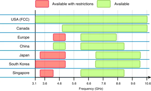
Figure8 3.1GHz -10.6 GHz UWB regulations in selected regions . . . 48
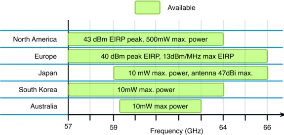
Figure9 60 GHz band regulations in selected regions . . . 49
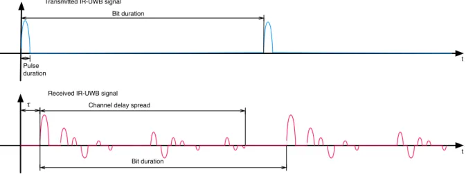
Figure10 Delay spread of IR-UWB signal . . . 51
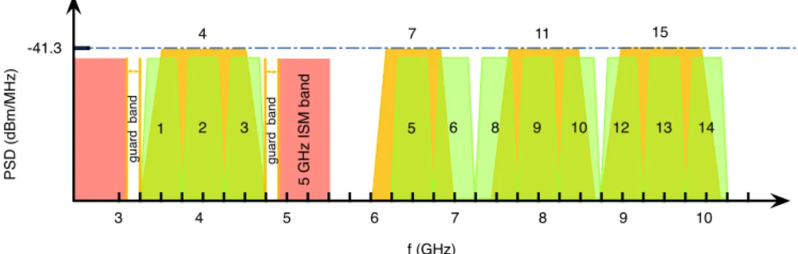
Figure11 IEEE 802.15.4a UWB band plan . . . 54
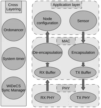
Figure12 Proposed cross-layer system . . . 64
Figure13 Time Division Multiple Access channel occupation . . . 65
Figure14 IR-UWB transceiver . . . 65
Figure15 Piconet architecture . . . 67
Figure16 Latencies involved and flag positioning for WiDeCS . . . 68
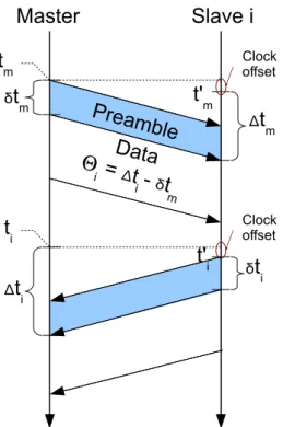
Figure17 Exchange of timing information . . . 68
Figure18 Proposed system architecture . . . 77
Figure19 Hardware simulation setup . . . 78
Figure20 Full working synchronization and localization in hardware sim- ulations . . . 79
Figure21 Effect of cluster tree architecture on synchronization . . . 80
Figure22 Hardware simulation of a fast changing channel’s effect on Time of Flight (ToF) estimation . . . 81
Figure23 RF front-end for the FPGA demonstrator . . . 83
Figure24 Block diagram of the proposed FPGA demonstrator . . . 84
Figure25 Block diagram of the proposed FPGA demonstrator . . . 85
Figure26 Scope captures of the FPGA demonstrator . . . 86
Figure27 ASIC Flow . . . 88
Figure28 Chip floorplan with all pads and corner cells implemented . . . . 92
Figure29 Chip floorplan with all pads and corner cells implemented . . . . 93
Figure30 Floorplan of WIDEMACV1chip . . . 94
Figure31 WIDEMACV1chip . . . 96
Figure32 Probe station setup for transmitted signal analysis . . . 98
Figure33 Time domain DAC output of WIDEMACV1, scope display . . . . 99
Figure34 Spectrum analysis of WIDEMACV1, scope display . . . .100
Figure35 Details of a data transmission occuring in a time slot . . . 100
Figure36 Setup for full connectivity check including PHY TX and RX, MAC, synchronization and localization . . . 101
10
Figure37 WIDEMACV1 test board . . . .102
Figure38 Face to face test modes . . . .103
Figure39 Histogram of delays between measurement triggers on master and slave nodes . . . .104
Figure40 Synchronization stability versus clock drift between nodes (@3GHz base clock frequency) . . . .105
Figure41 Power consumption versus clock frequency . . . .107
Figure42 Comparaison bande étroite / UWB . . . 8
Figure43 Etalement des échos sur l’IR-UWB . . . 9
Figure44 Système proposé . . . 12
Figure45 Délais successifs lors d’une transmission d’information sur un réseau sans fil . . . 13
Figure46 Echange d’informations de délais . . . 14
Figure47 Schema bloc du démonstrateur . . . 16
Figure48 WIDEMACV1 - vue CAO . . . 18
Figure49 FPGA Flow . . . 29
L I S T O F TA B L E S Table1 Quantitative performance comparison of synchronization protocols41 Table2 IEEE802.15.4a UWB frequency bands . . . 53
Table3 State of the art UWB systems . . . 59
Table4 Performance with face to face setup . . . .106
Table5 Comparison with state of the art UWB systems . . . .108
A C R O N Y M S
ACK Acknowledgement
ADC Analog-to-Digital Converter
AEA Adaptive Election Algorithm
AGC Automatic Gain Control
AHB Advanced High-performance Bus
11
AMBA Advanced Microcontroller Bus Architecture
AoA Angle of Arrival
ASIC Application-Specific Integrated Circuit
ASK Amplitude Shift Keying
B-MAC Berkeley Media Access Control
BER Bit Error Rate
BPSK Binary phase-shift keying
CBR Constant Bit Rate
CCA Clear Channel Assessment
CCA Clear Channel Assessment
CDMA Code Division Multiple Access
CMOS Complementary Metal Oxide Semiconductor
CNRS Centre National de la Recherche Scientifique
COTS Commercial Off-The-Shelf
CPU Central Processing Unit
CS Carrier Sense
CSMA-CA Carrier Sense Multiple Access with Collision Avoidance
CSMA-CA Carrier-Sense Multiple Access with Collision Avoidance
CSMA Carrier-Sense Multiple Access
CTS Clear To Send
DAC Digital-to-Analog Converter
DDS Direct Digital Synthesizer
DK Design Kit
DSP Digital Signal Processing
DSSS Direct-Sequence Spread Spectrum
DVFS Dynamic Voltage and Frequency Scaling
EHF Extremely High Frequency
EIRP Equivalent Isotropically Radiated Power
a c r o n y m s 13
EMC Electro-Magnetic Compatibility
EPP Energy Per Pulse
FCC Federal Communications Commission
FEC Forward Error Correction
FFD Full-Function Device
FFT Fast Fourrier Transform
FPGA Field Programmable Gate Array
GPS Global Positioning System
GTS Guaranteed Time Slots
GUI Graphical User Interface
HART Highway Addressable Remote Transducer
HD High Definition
HDL Hardware Description Language
I/O Input Output
IC Integrated Circuit
IEEE Institute of Electrical and Electronics Engineers
IEEE Inverse Fast Fourrier Transform
IP Intellectual Property
IR-UWB Impulse Radio UltraWide Band
ISM Industrial, Scientific and Medical
LAAS laboratoire d’Analyse et d’Architecture des Systèmes
LDPC Low-Density Parity-Check
LEACH Low Energy Adaptive Clustering Hierarchy
LNA Low Noise Amplifier
LO Local Oscillator
LoS Line of Sight
LPL Low Power Listening
LPL Low Power Listening
LR-WPAN Low-Rate Wireless Personal Area Network
MAC Medium Access Control
MACA Mobile-Assisted Connection-Admission
MB-OFDM Multi-Band Orthogonal Frequency-Division Multiplexing
MCM modulation, coding and multiple-acces scheme
MEMS MicroElectroMechanical Systems
MIMO Multiple Inputs, Multiple Outputs
MIT Massachusetts Institute of Technology
MPC MultiPath Component
MPW Multi Project Wafer
NDA Non Disclosure Agreement
NFER Near Field Electromagnetic Ranging
NP Neighbor Protocol
NTP Network Time Protocol
O-QPSK Offset Quadrature Phase Shift Keying
OFDM Orthogonal Frequency Division Multiplexing
OOK On Off Keying
OSI Open Systems Interconnection
PA Power Amplifier
PAMAS Power Aware Multi Access with Signaling
PAN Personal Area Network
PAPR Peak-to-Average Power Ratio
PBTS Perfectly Balanced Ternary Sequence
PCB Printed Circuit Board
PHY physical
PLC Power Line Communication
PLL Phase Locked Loop
PPM Pulse Position Modulation
a c r o n y m s 15
PR Place and Route
PSD Power Spectral Density
PSSS Parallel Sequence Spread Spectrum
PTP Precision Time Protocol
QAM Quadrature Amplitude Modulation
QoR Quality of Result
QoS Quality of Service
RAID Redundant Array of Independent Disks
RBS Reference Broadcast Synchronization
RF Radio Frequency
RFD Reduced Function Device
RFID Radio-Frequency IDentification
RM Reference Methodology
RS Reed-Solomon
RSSI Received Signal Strength Indication
RTL Register Transfer Level
RTS Request To Send
S-MAC Sensor MAC
SDR Software Defined Radio
SEP Schedule Exchange Protocol
SFD Start Frame Delimiter
SHM Structural Health Monitoring
SNR Signal to Noise Ratio
SoC System on Chip
SPI Serial Peripheral Interface
SSD Solid State Drive
T-MAC Timeout MAC
TDMA Time Division Multiple Access
TDoA Time Difference of Arrival
TEDS Transducer Electronic Data Sheet
TH-IR Time-Hopping Impulse-Radio
ToA Time of Arrival
ToD Time of Departure
ToF Time of Flight
TRAMA TRaffic-Adaptive Medium Access
UPF Unified Power Format
USA United States of America
UWB UltraWide Band
VCO Voltage-Controlled Oscillator
VHDL VHSIC Hardware Description Language
WiDeCS Wireless Deterministic Clock Synchronization
WiDeLoc Wireless Deterministic Localization
WLAN Wireless Local Area Network
WPAN Wireless Personnal Area Network
WSN Wireless Sensor Network
P U B L I C AT I O N S
Some ideas and figures have appeared previously in the following publications:
Awards and Honors
T. Beluch, F. Perget, J. Henaut;
Student Design Competition for Software Defined Radio;
IEEE Microwaves Theory and Techniques (MTT) division. IEEE International Mi- crowave Symposium (IMS)2012, Baltimore MD
T. Beluch, D. Dragomirescu, F. Perget, R. Plana;
Best Paper Award for Cross-layered synchronisation protocol for wireless sensor networks;
International Conference on Networks (ICN2010), Menuires (France),11-16 Avril 2010, pp.167-172URL : http://dx.doi.org/10.1109/ICN.2010.36
International Journals
T. Beluch, F. Perget, J. Henaut, D. Dragomirescu, R. Plana;
Mostly Digital Wireless UltraWide Band Communication Architecture for Soft- ware Defined Radio;
Microwave Magazine, IEEE , vol.13, no.1, pp.132-138, Jan.-Feb.2012URL: http://dx.doi.org/10.1109/MMM.2011.2174121 status: Published
T. Beluch, D. Dragomirescu, V. Puyal, R. Plana;
Low power digital TTL command for60GHz RF MEMS phase shifter;
Microelectronics Journal (Elsevier), Volume 42, Issue 12, December 2011, Pages 1321-1326, ISSN 0026-2692, URL : http://dx.doi.org/10.1016/j.mejo.2011.09.014 status: Published
T. Beluch, D. Dragomirescu, R. Plana;
A sub-nanosecond Synchronized MAC - PHY Cross-layer design for Wireless Sensor Networks;
Ad-Hoc Networks (Elsevier); http://dx.doi.org/10.1016/j.adhoc.2012.09.010; status:
Published online
International Conferences
D. Dragomirescu, M. M. Jatlaoui, S. Charlot, T. Beluch, P. Pons, H. Aubert, R.Plana;
Flexible integration techniques for wireless sensors network deployment: appli- cation to aircraft structure health monitoring;
International Workshop on Structural Health Monitoring (IWSHM2011), Stanford (USA),13-15Septembre2011, pp.1519-1526status: Published
T. Beluch, A. Lecointre, D. Dragomirescu, R. Plana;
Reconfigurable tactical impulse radio UWB for communication and indoor local-
17
ization;
International Conference on Networks (ICN 2011), St Maarten (Pays Bas), 23-28 Janvier2011, pp.235-240status: Published
T. Beluch, D. Dragomirescu, F. Perget, R. Plana;
Cross-layered synchronisation protocol for wireless sensor networks;
International Conference on Networks (ICN 2010), Menuires (France),11-16Avril 2010, pp.167-172 URL : http://dx.doi.org/10.1109/ICN.2010.36status: Published
T. Beluch, D. Dragomirescu, V. Puyal, R. Plana;
Actuation command circuit for60GHz RF MEMS phase shifters;
International Conference on Electronics Computers and Artificial Intelligence (ECAI 2009), Pitesti (Roumanie),3-5Juillet2009, pp.54-57status: Published
National Conference T. Beluch;
Architecture et modélisation de réseaux de capteurs sans fils synchronisés et localisée à faible consommation;
Journées Nationales du Réseau Doctoral en Microélectronique (JNRDM2011), Paris (France), 23-25Mai2011, 4p. status: Published
G E N E R A L I N T R O D U C T I O N
Recent advances in MEMS design and wireless technologies have opened the way towards new sensing techniques. Usually, sensors are deployed in two usual manners. Sensors can be placed far from the actual phenomenon in order to reduce perturbations caused by the sensor itself. This method leads to heavy signal processing to extract actual data from noise caused by the distance to the phenomenon. Another way of measuring an actual physical event is to place sensors in the desired area, and to perform data processing elsewhere. The drawback of this solution is that conventional sensors are often connected individually to the processing unit through multiple long cables requiring long and expensive deployment tasks.
Sensor networks consist in a large number of sensing nodes densely deployed in the desired area. These nodes are connected to each other through wired or wireless links, and work together for sensing physical events, processing them, and transmitting data to a sink point.
These features enable their use in various domains. Commercially available systems are already in use in military operations for example with the sucessful replacement of mine fields for intrusion detection with a hardened Wireless Sensor Network (WSN) designed for detecting intrusions. Other applications, such as Structural Health Monitoring (SHM) for large structures are under development, and experimentations are currently performed for the monitoring of railroads, highways, and other large scale transportation facilities. Other applications are appearing in the field of house automation, and allow the seemless deployment of a domotic system in an existing house for example. More recently, a new set of possible applications has been an active subject of research. This set is composed of applications requiring a large amount of data to be transfered continuously over the network. Indeed, measurement systems, such as for vibration measurement, do require a large number of sensors to acquire measurements with sampling frequencies up to50kSps, and are often asked to synchronize measurement trigger for all the sensors. The amount of data generated by hundreds of sensors with sampling rates in tens of kilosamples per seconds does rise higher than100Mbps.
The problems of trigger synchronization in WSNs and high datarate transceiver implementations for such networks are the two axis of work for this thesis.
For many years, high speed wired computer networks have concentrated a large part of the research about time synchronization. Network Time Protocol (NTP) and its improved variant: Precision Time Protocol (PTP) are widely recognized for use in wired networks. Performance attained by such protocols can reach a synchronization precision of100 ns. These protocols, however, use a large amount of data sent on the network, which leads to a high power consumption that is not affordable in WSN. New protocols have been developed that take into account specific needs for usability in WSN. These protocol, mostly lightweight, are based on a small number
19
of synchronization steps. A sync packet can be timestamped when transmitted, thus providing an approximate date to the receiver. Other methods include an handshake in the scheme. However, these protocols are limited by a recurring drawback of the standard network interfaces. Indeed, the network layers are mostly non deterministic in terms of latency, and do not allow precise time-stamping of the events.
On the other side, low power transceiver implementations have been proposed forWSNs. Most of them are based on the IEEE802.15.4standard, and do implement protocol stacks similar to the ZigBee stack. Such implementations do offer very low power consumptions. However, the datarate achieved by such transceivers do rarely exceed 250kbps. Academic researches have lead to low power transceiver implementations, using UltraWide Band (UWB) technologies, providing datarates up to 100 Mbps with energy per bit levels of 750 pJ/bit. A further improvement in the overall power consumption ofUWBsystems would allow longer lifecycles to
WSN nodes during use.
The work presented in this thesis is aiming at designing and implementing a System on Chip (SoC) architecture for use in WSNs. Improvements compared to the state of the art have been targeted in the cross layer design, as well as during the implementation of a mixed signalSoCproof of concept. The cross-layer design proposes a simple yet effective Medium Access Control (MAC) layer for fixed networks such as measurement setups. This design also uses and improves an implementation of a Impulse Radio UltraWide Band (IR-UWB) modulation scheme designed by Aubin Lecointre in his thesis. Innovative services are also proposed for synchronizing measurement triggers among all the nodes of the network.
In the domain of implementation, and power consumption reduction, the imple- mentation has been designed with the main objective of keeping the best data-rate and synchronization performance, with an energy consumption below the state of the art.
The first part of this thesis describes the potential uses forWSNs, as well as the state of the art in synchronization and implementations ofIR-UWBtransceivers. The context ofWSNsis detailed in chapter1. The use ofUWBin such networks is analyzed in chapter2, as well as the state of the art in low powerIR-UWBtransceivers.
The second part is focused on the design and implementation work proposed in this thesis. The chapter3describes the structure of the cross-layer designed system, and proposes WiDeCS as a solution for improving synchronization performance inWSNs. The implementations of the proposed system inFPGA prototype andASIC
are detailed in chapter 4. This last chapter also provides information about the specific test protocol developed for verifying the system’s performance, and the results obtained are compared with state of the art low power implementation.
Part I
C O M M U N I C AT I O N I N W I R E L E S S S E N S O R N E T W O R K S
WSNshave been made possible thanks to innovations that have occured in the last two decades in the domains of microelectronics, integration, sensors, and energy harvesting. They are currently exploding in terms of usage and attainable performances, and improve the way of working in many contexts. Mine fields, for example, have been successfully replaced by efficient intrusion detection systems based on a large number of wirelessly connected autonomous elements. Other applications, such as railroad or building monitoring are being experimented around the world.
New modulation techniques, routing protocols, MAC schemes specifi- cally developed for a use inWSNshave allowed their use in new domains of activity. This part details some of the most interesting wireless com- munication techniques and how they expand the number of possible applications by allowing them to use an adapted communication scheme.
An introduction about WSN is first given. The different methods for transmitting data in such networks are then detailed, and specific new modulation techniques, called UWB are studied through an example:
IR-UWB.
I N T R O D U C T I O N T O C O M M U N I C AT I O N I N W I R E L E S S
1
S E N S O R N E T W O R K S
Wireless Sensor Network (WSN) is describing systems composed of sensing elements embedded with wireless communication ability and a variable part of autonomy.
These Wirelessly connected sensor networks are often given functionality such as data gathering to gateway nodes also known as sink points, sensor heterogeneity or even actuation abilities. However, the possibilities of such sensor networks are not limited to these two functions. One can use aWSNto detect intrusions in a specific area, and trigger adapted alarm systems or even countermeasures. On the other side, the same technology can be used for monitoring a patient’s vitals, and alert the medical crew when something goes out of chart such as an abnormal pulse rate, or epileptic ceasure.WSNis then a new basis for emerging products and applications.
However, there is not a single solution for all applications, but rather a framework serving as a starting point for developing application specific solutions.
This chapter first describes some of the possible applications forWSNselected with regard to their interest for this work. Communication patterns used inWSNsare then studied in a second section. The last section of this chapter describes two services for WSNs necessary for the applications targeted in this thesis : synchronization schemes, and ranging and positioning methods.
1.1 a p p l i c at i o n s f o r w i r e l e s s s e n s o r n e t w o r k s
Sensor networks are not bound by standardization constraints. This expression ac- tually describes every system composed of nodes with sensing capabilities commu- nicating with each other in order to perform a task assigned to them. Applications linked to such systems are then possible in almost every domain of everyday’s life. This section gives an overview of the possible applications, and points out the reason whyWSNtechnologies can improve the way of working in this application.
1.1.0.1 Military and security related applications
• Intrusion detection: Sensor networks can be deployed over a surface to detect any movement of an unauthenticated target. The exact position of this target can also be assessed thanks to the positions of the nodes in detecting range of the target. Such systems are under experimentation as a replacement to mine fields for detecting an enemy presence in a demilitarized zone. Such a system, as presented in figure ??, may be used for detecting an intrusion either by checking the status on site, or by means of remote monotoring.
• Impact damage assessment: Sensor networks are used as SHM equipments placed on a vehicle for assessing the status of a part that has taken damage
23
Monitored area On-site monitoring
Remote monitoring
Figure1: Example of a military oriented intrusion detection system
from an enemy shot [3]. Such systems help taking operational decisions thanks to the knowledge available concerning the overall damages taken by the vehicle.
• Mission reconnaissance: Sensor networks can be deployed prior to the mission in order to gather better information about the status of enemy troops and defense systems. Such deployment can be performed either by undercover agents or by means of sparse drop of SmartDust like motes. Such networks can then operate discretely and give useful information to plan a mission.
• Missile guidance and targeting: A Sensor network composed of multiple static nodes can help guiding a missile towards a moving target. The position of the moving target is obtained via conventional positioning schemes such as trilateration or triangulation of data obtained through a network of sensing elements such as passive and/or active radars, infrared video-cameras, vi- bration sensors or even motion detectors. Knowing the precise location of a missile allows real time flight parameter correction improving its accuracy.
• Detection of dangerous materials: Sensor networks can be deployed in critical buildings such as airports for detecting dangerous compounds. Gas or radia- tion detectors, embedded in every sensing node, increase the probability of detecting hidden explosive devices or radiating materials.
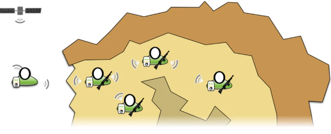
• Squad members health and location monitoring: Knowing the status of every team member is often a matter of life or death for the entire squad. Such applications can be found in military contexts such as urban warfare, where squad members are sometimes spread to better scour a building. Knowing where a squad member is located, as well as his or her status can be useful.
1.1 a p p l i c at i o n s f o r w i r e l e s s s e n s o r n e t w o r k s 25
Figure2: Example of a military oriented squad health monitoring equipment It can indeed help in avoiding loosing a full squad in an ambush because a squad member has been silenced before he could warn the squad leader. These systems are planned to look like a PDA showing in real time the location of every squad member, as well as his vitals and his orders. The example in figure2 shows an operation manager with a channel to a communication satellite exchanging data with a squad exploring a cave. Members of this squad each possess a PDA like apparatus logging their relative position, as well as vital parameters. This example then shows how communication and localization services can be brought to closed space with no need for a prior deployment of localization anchors.
1.1.0.2 Industrial applications
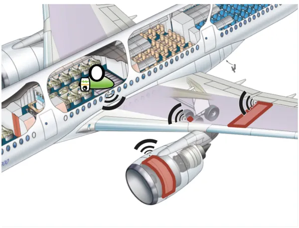
• Test and validation: Every item sold on the market must be tested for multiple reasons. The first and obvious one is to check the conformity of the product with its design. However, there are many other reasons for testing a product, each reason will require a set of test conditions and expected results. For example Federal Communications Commission (FCC) certification implies to verify the power radiated by a communicating device, as well as the power spectral density of the radiated signal. Such tests are usually made in an anechoic room and do use spectrum analyzers to qualify the measured spectrum with regulations. Other tests will require to check air pressure over and under a plane’s wing to check its compliance with the requirements, as well as conformity to aeronautics related regulations. Such air pressure measurement is often performed using pressure sensors placed inside the wing and connected to the measurement site through a hose. Replacing this setup with thin wireless nodes providing similar results would divide the overall cost of installation and removal by four. For example, placing a pressure belt on a plane’s tail allows a few tenths of sensors to be placed on the tail at the cost of more than one month of immobilization of the plane. Indeed, such pressure belts are extremely complex, and require a large number of
Figure3: Example of an in-flight testing context
cables to be routed in the plane’s structure to the cabin. The figure3shows various communicating modules placed at different places of a same plane which are communicating with an equipment inside the cabin. Such systems would allow aerospace industry to provide a monitoring equipment to a client for mounting on a suspected part of a plane during operation. Results of this monitoring would then be logged inside a computer in the cabin, and sent back to the support team for study of these logs. Such systems would drastically reduce the cost and duration of ground maintainance for planes.
• Building structural health monitoring: The complexity of building has been rising for the last decades, with higher towers, longer and thinner bridges, and other innovative buildings. Such improvements are often the result of a trade- off. Mechanical constraints computing has improved, and now allows lighter structures to be used. However, monitoring these vital points has become more important to the health of these new structures, as the overcompensation is nowadays much smaller. Sensors networks are more often deployed in newly built buildings, as well as in building that may be subject to problems with their structure. These sensors help in detecting fatigue cracks and de- formations. These new techniques for monitoring the status of a building are often used for monitoring new building structures, especially when these structures represent a breakthrough in the technique, such as skyscrapers or unconventional buildings [79] (figure4). However, buildingSHMsystems,
1.1 a p p l i c at i o n s f o r w i r e l e s s s e n s o r n e t w o r k s 27
(a) Burj Khalifa in Dubai (828m) (b) Marina Bay Sands in Singapore (146m) Figure4: Examples of monitored buildings
mostly based on fiber optics, have also been used in the more unexpected context of archeological buildings such as the Torre Aquila in Italy [28].
• Vehicle structural health monitoring: Recent vehicles such as cars and trucks do propose automatic diagnostic features, which are getting smarter with time rolling. WSN based SHM systems are opening the way to even better diagnostics based on the quantization of wear and tear on critical parts of an engine or even the early detection of damaged tires to avoid accidents. Such
SHM is also seen as a promising solution to improve the reliability of airplanes, trains, and other public transport.
• Maintenance automation: The automated diagnostics based onWSNscan also be extended to ease maintenance by reporting parts that need to be changed to the mechanic.
• Energy optimization: Smart buildings are able to manage energy sources to reduce the consumption of commercial energy. Indeed, moving air between an area overexposed to sunlight and shadier areas helps in reducing power consumption related to air conditioning. WSNshelp in performing these tasks by providing the best granularity available to the system.
• Inventory management:RFIDtags have helped improving processes in logistics and inventory management. Tagging orders and parcels helps in keeping a constant knowledge about its location among the different storage centers and delivery trucks. However, sensing tags are at the limit between Identification tags, and intelligent nodes equipped with sensors. Such tags allow logging the temperature of a transported good, and give reliable information when this good is delivered to the end user. Such information can also be automatically
transferred from the goods to an inventory management unit which would be in charge of the status of every goods, and would advise the manager on his storage facilities.
1.1.0.3 Health care applications
• Physiological data monitoring: Sensors placed at the best spot on or in the patient’s body are connected together and continuously send physiological data to a hub unit which relays this data to the medical crew [77]. Non invasive sensor networks reduce the constraints caused by a patient’s condition when compared to a constant monitoring in a medical unit. Indeed, such equipment make it possible for a patient to go shopping while being remotely monitored and kept healthy.
• Patient identification, localization and personal data storage: The number of hospitals usingRFIDtags in constantly growing for patient identification. RFID techniques have allowed to improve patient management in hospitals in the last decade [49,32,65]. Current research are made towards smart identification tags coupling the physiological data monitoring with patient identification tasks [29].
• Automatic drug administration: Sensor networks can be used for constantly adapting the administration of a drug to a physiological data measured on the body, or even to a target dosage of the drug present in the patient’s blood.
1.1.0.4 Environmental applications
Wireless Sensor Networks (WSNs) used for environmental applications are similar to each other. Indeed, most of them are deployed on wide areas, with no access to a conventional power source, and are required to regularly measure, analyze, detect and alert when abnormal measurement values are detected. Communications used in such applications are often long range and low data rate wireless transmissions.
• Flood detection: Sensors networks are used to protect areas presenting a high risk of flooding as shiwn in figure5. Placed at strategic points for detecting a rise in the water level, they can provide early alerts in case the water level becomes abnormal[71].
• Fire detection: Gas or ultraviolet light sensing WSNscan be spread in a forest for detecting a fire outbreak as soon as it happens [26, 31].
• Pollution study: Pollution study stations are often heavy and costly boxes containing spread over a territory to monitor the presence of pollution related gases and volatile compounds. However, sensor networks are currently re- searched as a solution to improve the measurement granularity by increasing the number of sensing elements, and their dispersion in the monitored area through integration in vehicles [54].
1.2 c o m m u n i c at i o n f o r w s n s i n a n i n d u s t r i a l c o n t e x t 29
Usual water level Abormal water level
Figure5: Example of a flood detection context
1.1.0.5 Consumer use applications
• Smart cars: Increasing the part of automation in a car is one of the keys to reduce the number of car crashes. Among the possible technologies for increasing the intelligence of a car, a network composed of cars in range of each other exchanging data about traffic conditions can improve the overall road safety. Inter-car communications are planned in most of the frequency allocation regulations, and are allowed on specific spectrum bands.
• Home automation: Automating a house in order to optimize its energy con- sumption while keeping it welcoming to its owner is a growing market.
However, this market is ruled by a major parameter : the price of the equip- ment necessary to reach a satisfying behavior for such automation systems.
Sensor networks can indeed be used to detect the presence of a person in a room in order to turn on or off the equipment present in this specific room.
Shaders can be automatically opened to allow sunlight to enter the house during the day, and closed to prevent heat to leave the house through the windows during the night.
1.2 c o m m u n i c at i o n f o r w s n s i n a n i n d u s t r i a l c o n t e x t
Basebands forWSNsare designed with a specific range of applications in mind. Two types of requirements can be identified for sortingWSNs.
SHM applications often require a system to be installed for long periods on a monitored structure. Those systems aim at regularly checking physical measure- ments taken at relevant points of this structure and detect unusual changes in its mechanical parameters. In the case of a Sky-tower, it could mean to regularly monitor strain along the metallic core, as well as on a few selected floors.
These monitoring systems have to periodically take measurements, and dispatch them to a master unit. Considering that monitoring most of the common struc- tures do rarely require sampling rates over 10 samples per second, it is often sufficient in such applications to transmit data regularly at second scale intervals.
The corresponding system will be considered low data rate in the following thesis.
However, some structures, to be monitored, require the use of active monitoring systems. Applications for such systems include studying the propagation of seismic waves through a building, or detecting bullet impact on military structures, along with damage estimation.
1.2.1 Low data rate communications
Low data rate communications are often used in the case of low power nodes remaining idle for the major part of the time. These networks are often waiting for long periods between packet exchanges, and do require specific synchronization between the clocks to allow planning periods when every node has to be listening on the network. Such scheduling makes it possible to turn off every radio interface between these periods, and then save large amounts of power compared to usual always-on network architectures.
1.2.1.1 IEE802.15.4-2006, a Standard for WSNs
The most spread standard for wireless communication aimed at WSNapplications is IEEE 802.15.4-2006 [13]. This standard provide multiple physical (PHY) layer and MAC layer specifications for transmitting data with a low power consump- tion. This standard defines such communications in a Wireless Personnal Area Network (WPAN) context ranging up to 10 m, whereas many implementations demonstrate ranges up to 2 km. The proposed physical layers, as in the 2006 revision, include three variants of a Direct-Sequence Spread Spectrum (DSSS) mod- ulation scheme based on Offset Quadrature Phase Shift Keying (O-QPSK), and a fourth modulation based on the combination of Binary phase-shift keying (BPSK) and optional Amplitude Shift Keying (ASK) based on Parallel Sequence Spread Spectrum (PSSS). ThesePHYlayer allow channel data-rates up to250kbps in the2006 release of this standard. Newer releases beginning with the IEEE802.15.4a bring higher data rates, and are listed in the High data rate communication subsection.
The network interface described in the IEEE 802.15.4standard are widely used in WSNs because of a low power consumption, and long transmission ranges.
Applications have been developed in the field of SHM, with examples in bridge monitoring in the USA [50]. Home automation systems are currently sold using a ZigBee transmission system based on this standard for allowing the placement of various sensors at different places of a house without need for wiring them to the automation manager [5]. Actuators related to home automation, on the other side, are often interfaced through Power Line Communication (PLC) because most of the possible actuators do require levels of energy that cannot be achieved with batteries.
1.2 c o m m u n i c at i o n f o r w s n s i n a n i n d u s t r i a l c o n t e x t 31
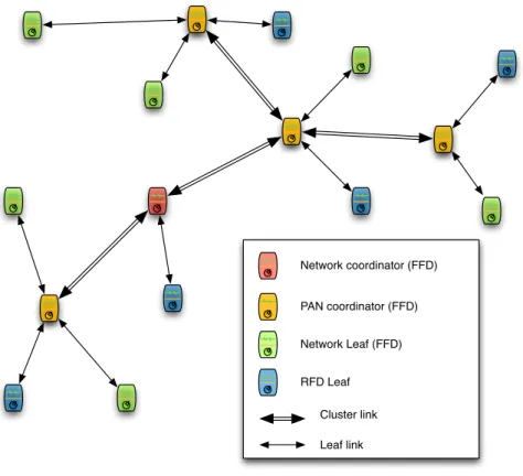
Network coordinator (FFD)
PAN coordinator (FFD)
Network Leaf (FFD)
RFD Leaf Cluster link Leaf link
Figure6: IEEE802.15.4cluster tree architecture
Many other applications with low needs in terms of quantity of data transmitted do use ZigBee as the main network interface.
TheMAC layer described in this standard combines multipleMACschemes. The choice of the used scheme is performed by a higher layer. A simple Aloha scheme is mandatory in the standard and does allow immediate transmission of new data with no regard to the channel occupation. This allows cheap Reduced Function Devices (RFDs) modules to communicate with Full-Function Devices (FFDs). A Carrier-Sense Multiple Access with Collision Avoidance (CSMA-CA) scheme is also described, as well as a super-frame structure for permanent slot allocation. The described MAC
layer then allows the simpler devices to communicate at low data-rates, whereas
FFDs have the possibility to bring order to the used channel and then improve the data-rates. The usual structure for implementing a IEEE802.15.4network is a heterogenous cluster tree network composed ofFFDs andRFDs. FFDscan be acting acting either as network / Personal Area Network (PAN) coordinators, or as network leafs.RFDs, on the other side, can only act as leafs on the network. An example of a IEEE 802.15.4cluster tree architecture is shown in figure6. The possible uses for each type of node in this network architecture is displayed in this schematic.
This standard, however, has served as the basis to many of the most known low cost low power radio interfaces such as ZigBee [2], MiWi [74], and other constructor specific implementations.
1.2.1.2 WirelessHART
Highway Addressable Remote Transducer (HART) protocol is a digital industrial automation protocol based on field-bus. Its main uses are in the field of industrial process automation by providing a reliable data transmission interface for linking the different elements used in an industrial process to the control unit. Among the elements that can be linked to the control unit are sensors for measuring parameters during the process’ execution, and actuators for executing the process itself. The performance in terms of data rate is relatively low when compared to other wired networks. However, this open protocol has an optimized packet structure, and do produce a reduced overhead.
WirelessHART is an implementation of the HART protocol over a wireless link.
The radio interface chosen for this wireless implementation is IEEE 802.15.4. A
HART compliant network management protocol in implemented on top of the wireless interface to allow seamless integration in a usualHARTcompliant network.
WirelessHART sensors and actuators can be added in a HART industrial control system by adding a WirelessHART adapter on theHARTnetwork.
This protocol, along with the wiredHARTprotocol, do provide industrial grade communications with reliable data transmission and optimized packet structure.
However, none of the implementations proposed are suitable for high data-rate applications.
1.2.1.3 IEEE1451
IEEE 1451 standard[14] is not a wireless communication standard. However, this standard describes smart transducer interfaces for connecting transducers (including sensors and actuators) to instrumentation units, and process control and manage- ment units. The interfaces described by this standard include network independent communication interfaces for connecting these transducers. The main point of this standard resides in the Transducer Electronic Data Sheet (TEDS) format description, which aims at integrating a digital data-sheet inside every transducer. This TEDS
contain transducer identification, calibration, correction data, and manufacturer- related information. The main goal of the IEEE 1451is to allow access to the TEDS
with no regards to wether the network is wired or wireless. As IEEE1451.5version of this standard,TEDSare compliant with four wireless network interfaces including 802.11WiFi, Bluetooth, ZigBee, and6LoWPAN. RFID access toTEDShas been added with the2010version of the standard.
1.2.2 High data rate communications
High data-rate communications are necessary in applications in which the amount of data to be transmitted between the nodes becomes higher than10Mbps, or when the number of nodes required to send data simultaneously rises up to hundreds of nodes. In this case, it is no longer useful to plan sleeping periods. However, energy management and routing protocols become important if the energy is not provided by a reliable source. In this case, most of the systems described above do
1.2 c o m m u n i c at i o n f o r w s n s i n a n i n d u s t r i a l c o n t e x t 33 not comply with these specific requirements. Zigbee is limited to250kbps in most of its use cases. IEEE802.15.4was also limited to250 kbps in its2006version [13] until a newer version, allowing higher throughput was released under the name IEEE 802.15.4a or 802.15.4-2011 [18]. As of 2008, the only systems commercially available for use in Wireless Sensor Networks (WSNs) were limited to 250 kbps.
Since then, multiple paths have been tried to propose a low-power high-throughput radio interface forWSNs
Methods for improving the data-rate of a wireless network vary and include channel binding, Multiple Inputs, Multiple Outputs (MIMO) channel separation,
UWBcommunications, Orthogonal Frequency Division Multiplexing (OFDM) based modulations, and the use of Extremely High Frequency (EHF) frequency bands.
However, most of these technologies do imply a rise in power consumption due to more complex computing, wider band modulations requiring higher functioning frequencies, and higher propagation loss due to increased free space loss and molec- ular resonance. The following paragraphs does study the most promising solutions for performing high data-rate communications. Their respective complexity is also studied, and their use in the case ofWSNs is studied.
1.2.2.1 IEEE802.11WiFi
WiFi networks have evolved from the first standard versions allowing 11 Mbps
PHY data-rates in the 802.11b version [7] of the standard, up to 6.93 Gbps with the 802.11ac version [4] of this standard in MIMO with channel binding and 256 Quadrature Amplitude Modulation (QAM) modulation. This wireless network stan- dard is the most widely used for communications between computers, handheld devices, and more recently set top boxes. The main advantages of WiFi has always been the compatibility between devices implementing different versions of the same standard, as well as high data-rates. Indeed, an access point compatible with 802.11n version, is supposed to be able to communicate with802.11b devices, if the configured security protocol remains compatible with the older device. On the other hand, this compatibility has a main drawback in the fact that the whole data-rate of the wireless network is determined by the highest data-rate attainable by every node connected to the same access point. An active 802.11b device connected to a 802.11g access point does limit the whole data-rate to 11 Mbps instead of “g”
version’s54Mbps. The other advantage is the extremely high data-rates, which are reaching6.93Gbps in the802.11ac version of this standard.
However, this rise in data-rate, as allowed by the latest version of this standard comes with strong drawbacks. The first and foremost among them is the high system complexity needed for reaching such data-rates [4]. Indeed this version requires multiple antennas on both the transmitting and receiving sides in order to increase the data rate through MIMO multi-chaneling. The size and power consumption of a WSN node would become unacceptable in most of the application schemes.
Moreover, these data-rates are reserved to systems such as laptop, computers, and wireless routers and access points. Handheld devices are only allowed lower
data-rates, which is mostly due to a smaller number of integrated antennas for
MIMO, as well as complex computations needed for receiving data correctly [4].
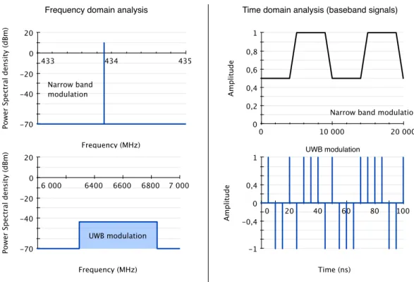
1.2.2.2 UWB modulations
UltraWide Band (UWB) modulations are technologies which have known a growing interest in the last decade. Foundry technologies have improved the maximum frequency attainable for digital Application-Specific Integrated Circuits (ASICs), thus opening the way to wider band modulations. Indeed,UWBmodulations are often seen as a way to simply improve the throughput of a channel. An example is the ECMA368 standard [37], which is mostly based on OFDMmodulation. These systems do offer higher data-rates, thanks to their higher bandwidth. However, this increase in throughput is countered by new requirements in terms of working frequency, algorithm complexity, and power consumption. Lower complexity imple- mentations ofUWBmodulations have been proposed for use in measurement WSNs
[53]. On the other side, the power consumption remains too high for autonomous nodes. OtherUWBmodulations based onIR-UWBexist, and are listed in section 2.2. These solutions, on the other side, have been a growing subject of interest from scientists, but they require deep developments for implementing, and have only been standardized recently in the IEEE802.15.4a (see section2.2.2).
The work presented in this thesis is mostly based on the use ofIR-UWB PHYlayers presented in A. Lecointre’s thesis, in which modifications were made for supporting Time of Arrival (ToA) measurement.
1.2.3 power-saving MAC protocols
This section lists the major MAC protocols used in the case ofWSNs. Medium Access Control (MAC)is an important technique that enables the successful operation of the network. Medium Access Control in the case of wireless sensor networks has been a very active research area in recent years. The usual wireless medium access control protocols such as 802.11 WiFi protocol is not suitable for such network applications because of a high complexity, as well as multiple different possible computations depending on the heterogeneity of the network. Considering that
WSNs are composed of battery or super-capacitor powered nodes, such complex
MACprotocols must be replaced by new less complex protocols with no requirement for high speed processing units [58].
TheMAC protocol used then has to address the following energy related issues:
• Collisions: Collisions occur when more than a single node are transmitting at the same time. The resulting signal present on the channel is then a com- bination of the signals transmitted by both the emitting nodes. The result of a collision is lower Bit Error Rate (BER) performance, and often the complete loss of the information transmitted by the colliding nodes. This causes an energy loss due to the need of resending the information, and to the cost in energy of the useless collided transmission. Collision avoidance is then a mean to reduce the energy consumption of a WSNnode.
1.2 c o m m u n i c at i o n f o r w s n s i n a n i n d u s t r i a l c o n t e x t 35
• Overhead: Overhead refers to the data transmission required for assuring a proper Medium Access Control (MAC). This data is not related to the application itself, but it is necessary for the network to setup properly, and to avoid collisions. The reduction of the overhead improves the efficiency in terms of energy per bit of application related data. However, lower overhead may reduce the stability of the network, and cause packet loss, collisions, and overhearing.
• Overhear: A cause of energy loss in wireless networks is the fact for a node of receiving data which is not intended to it. Consequences are more visible in wireless networks than in wired networks because of frequent pream- bles which are necessary for synchronizing the receiving PHY layer to the modulated signal. Simple overhear reduction techniques such as stopping the reception after having checked a destination MAC address is then not appropriate for every network.
• Idle listening happens when a node is listening on the channel, waiting for a possible data to receive. Listening to the channel has a cost caused by the combination of two causes. The first cause is the time being actually lost while listening on the channel, and waiting. The other cause for the cost is the actual power consumption of idle listening. Reducing either one or another of these causes will reduce the overall cost of idle listening.
• Complexity: As we stated in the introduction of this section, the complexity of a protocol causes multiple effects at different moments of the use of this protocol. A complex protocol will require more computing capabilities from the communicating node. This causes a higher power consumption of the Integrated Circuit (IC) chip because of larger areas required, as well as higher operation frequencies.
Successfully solving these issues with regard to requirement specific to the target applications is the main goal ofWSN orientedMAC protocols. TheMAC protocols proposed forWSNs can be divided into two categories namely Contention based and Schedule based.
Schedule based protocol can avoid collisions, overhearing and idle listening by scheduling transmit and listen periods. However, these protocols have strict time synchronization requirements and do often require a higher complexity logic for synchronization purpose.
The contention based protocols, on the other hand, relax time synchronization requirements. These protocols are based on Carrier-Sense Multiple Access (CSMA) techniques, which are more adapted to changing network topologies, due to a high tolerance to new nodes joining the network, or to the ones leaving it. Their complexity is also often lower than schedule based protocols. However, they un- derperform in terms of solving the above listed energy related issues. Indeed they present higher costs for message collisions, overhearing, and idle listening.
Among the existingMAC protocols, the following protocols represent a panel of variousMAC protocol types and implementations.
1.2.3.1 Sensor MAC (S-MAC)
The Sensor MAC (S-MAC) protocol was introduced to solve the energy consumption related problems of idle listening, collisions, and overhearing inWSNs using only one transceiver [59]. S-MAC considers that nodes do not need to be awake all the time given the low sensing event and transmission rates. A contention based
S-MACprotocol is based on Carrier-Sense Multiple Access with Collision Avoidance (CSMA-CA). Energy conservation and selfconfiguration are primary goals, whereas latency and determinism are considered less important. TheS-MACprotocol reduces energy loss due to collision, overhearing, packet overhead and idle listening by turning the radio on and off based on the fixed duty cycles. The main drawback of
S-MACis that the use of fixed duty cycles can waste considerable amounts of energy since the communication subsystem is activated even though no communication will take place.
1.2.3.2 Timeout MAC (T-MAC)
Timeout MAC (T-MAC)[98] is aMACprotocol based on theS-MACprotocol possessing an adaptive timeout instead of a fixed duty cycle. Each slave node goes to a sleep period if no activation event has occurred for a defined duration. Such an event can be reception of data, start of listen/sleep frame time etc. The T-MACprotocol introduces the idea of having an adaptive active/inactive (listening/sleeping) duty cycle to minimize the idle listening problem and improve the energy savings over the classic CSMAandS-MAC fixed duty cyclebased protocols [59]. The T-MAC
protocol, however, may often make the slave nodes oversleep, and then miss a data transmission that was occuring during a sleeping period. This oversleeping can highly increase the overall latency between the time a packet is being put on the network, and the time it is well received by the target node. This protocol is then better suitable for event based low data-rateWSNs with low requirements in terms of latency.
1.2.3.3 Berkeley Media Access Control (B-MAC)
The Berkeley Media Access Control (B-MAC) protocol [59] is a CSMA based MAC
protocol for WSNs. B-MAC introduces several interesting mechanisms and features.
One mechanism is the Clear Channel Assessment (CCA) for effective collision avoidance, which takes samples of the media to estimate the noise floor.B-MACalso utilizes a preamble sampling like technique called Low Power Listening (LPL) to minimize the idle listening problem. Finally, B-MACincludes the use of ACKframes for reliability purposes and throughput improvement. Moreover,B-MAC is able to function with B-MAC mechanisms, such as the CCA, acknowledgments, and LPL
disabled to tradeoff power consumption, latency, throughput, fairness or reliability.
The main drawback of this protocol is the stringent requirements in terms ofPHY
layer adaptations that need to be implemented for the mechanisms such as CCA
and LPLto function.