HAL Id: inria-00394466
https://hal.inria.fr/inria-00394466
Submitted on 2 Dec 2009
HAL is a multi-disciplinary open access archive for the deposit and dissemination of sci- entific research documents, whether they are pub- lished or not. The documents may come from teaching and research institutions in France or abroad, or from public or private research centers.
L’archive ouverte pluridisciplinaire HAL, est destinée au dépôt et à la diffusion de documents scientifiques de niveau recherche, publiés ou non, émanant des établissements d’enseignement et de recherche français ou étrangers, des laboratoires publics ou privés.
A simple approach to nonlinear tensile stiffness for accurate cloth simulation
Pascal Volino, Nadia Magnenat-Thalmann, François Faure
To cite this version:
Pascal Volino, Nadia Magnenat-Thalmann, François Faure. A simple approach to nonlinear tensile stiffness for accurate cloth simulation. ACM Transactions on Graphics, Association for Computing Machinery, 2009, 28 (4), pp.Article No. 105. �10.1145/1559755.1559762�. �inria-00394466�
Simple, yet Accurate Nonlinear Tensile Stiffness
Pascal VOLINO
Nadia MAGNENAT-THALMANN
MIRALab, University of Geneva, Switzerland Francois FAURE
LJK, INRIA, University of Grenoble, France
Recent Particle System models have evolved toward accurate representation of elastic stiffness based on continuum mechanics, converging to formulations that make them quite analogous to fast Finite Element methods. These formulations usually involve the linearization of tensors that help their formulation in the context of linear elasticity. Toward our objective of simulating the nonlinear properties of cloth accurately, we show through this work that this linearization can indeed be suppressed and replaced by adapted strain-stress laws relating precisely the nonlinear behavior of the material. This leads to very streamlined computations that are particularly efficient for simulating the nonlinear anisotropic tensile elasticity of deformable surfaces. Through a simple and efficient implementation using the Particle System formalism, we demonstrate the efficiency of this method with examples related to garment simulation.
Categories and Subject Descriptors: I.6 [Computing Methodologies]: Simulation and Modeling; I.3.5 [Computing Methodologies]: Computer Graphics - Computational Geometry and Object Modeling - Physically-Based Modeling; J.6 [Computer Applications]: Computer-Aided Engineering.
General Terms: Mechanical Simulation, Cloth Simulation.
Additional Key Words and Phrases: Particle Systems, Finite Elements.
1. INTRODUCTION
The mechanical properties of cloth materials are highly isotropic and nonlinear: The internal forces in the material are not at all proportional to the deformations, and they furthermore vary much with their orientation relatively to the thread directions. This anisotropy and nonlinearity still creates significant challenges when it comes to define a mechanical simulation system that would accurately reproduce these effects on virtual objects, which would also be applicable for actual applications such as accurate CAD systems (Figure 1). At the meantime, interactive and Virtual Reality applications require very efficient simulation models that compute quickly enough for offering good reactivity to user interaction.
Combining these requirements is still one of the main challenges of cloth simulation, and we will contribute to address this by showing that nonlinearity is indeed not necessarily synonym of complex implementation and slow computation, and that the way-too-often unconsidered hyperelastic St.Venant-Kirchhoff materials can indeed be key actors in accurate interactive cloth simulation.
1.1. Existing Simulation Schemes
Particle Systems have always been of large interest in the field of cloth simulation, and more generally in the field of interactive mechanical simulation, as they offer a simple, intuitive and flexible way to model mechanical systems. Furthermore, they can be combined with a large range of numerical integration schemes, according to the
important features of the simulation context (dynamic accuracy, convergence speed, fast and approximate simulation, robustness...).
Early Particle Systems were grid-based [Breen et al, 1994] [Eberhardt et al, 1996], and already featured simulation of nonlinear behavior curves through formulations that made them quite analogous to continuum- mechanics models. They were however fairly limited accuracy for large deformations, and required quite long computation times. Faster models, based on spring-mass grids, have once again become popular since implicit integration methods have started to be used for Particle Systems [Baraff and Witkin, 1998], because they allowed a simple expression of the Jacobian of the particle forces while requiring only simple computations [Desbrun et al, 1999] [Meyer et al, 2001] [Choi and Ko, 2002]. Combined with advanced implicit integration methods [Eberhardt et al, 2000] [Hauth et al, 2001] [Volino and Magnenat-Thalmann, 2005], these simulation schemes have particularly become popular for real-time and interactive applications. Unfortunately, spring-mass systems are quite unable to model surface elasticity accurately. Although some techniques have been developed to identify their parameters to those of the simulated material, they do not allow full discrimination between deformation modes [Bianchi et al, 2004], and they remain particularly inaccurate for anisotropic and nonlinear models. Particle Systems, as a whole, have inherited this reputation of inaccuracy from them.
On the other hand, Finite Elements have now acquired a good maturity for mechanical simulation. Their traditional field of application is elastic solid or shell modeling for mechanical engineering purposes, a context where linear elasticity and small deformations are the rules. These formulations are not so well adapted to very deformable objects such as cloth, and early attempts to model cloth using high-order elements [Eischen et al, 1996]
led to impractically high computation times.
Figure 1: Accurate simulation of nonlinear anisotropic cloth materials is required for garment prototyping applications.
Some recent developments have attempted to speed up the computation times required for Finite Elements.
These have particularly been used for simulating deformable volumes in the context of interactive simulation for virtual surgery systems [Debunne et al, 2001] [Hauth et al, 2003]. For instance, pre-inverting the linear system matrix (as done by [Desbrun et al, 1999] for Particle Systems) may speed up the computation [Bro-Nielsen and Cotin, 1996], but restricts the application field to linear models and very small mechanical systems [James and Pai, 1999]. “Explicit Finite Elements” [O’Brien and Hodgins, 1999] come close to good computational charge compromise by locally approximating the solution of each element [Cotin et al, 1999]. However, these models rely on simple linear elasticity which is inappropriate for the large deformations or displacements encountered in cloth simulation. Alleviating this problem through the use of a linearized form of the Green Lagrange strain tensor has recently led to more accurate models [Debunne et al, 2001] [Etzmuss et al, 2003]. At the meantime, Particle Systems have also evolved toward accuracy, and there is indeed a significant convergence in the formulation of accurate Particle System models based on continuum mechanics [Etzmuss et al, 2003] with their Finite Element counterparts, as both describe accurately surface elasticity through representations of the Green-Lagrange strain tensor with various degrees of linearization, and these intermediate approaches allow very efficient simulation [Teschner et al, 2004].
One major drawback remains with these accurate schemes: They are only applicable in the context of linear elasticity. In most models, this limitation essentially results from the linearization process commonly used to turn the Green-Lagrange tensor into a linear Cauchy tensor. In order to preserve accurately for large deformations, this is carried out by rotating the coordinates system of parameter space of the elements so as to match the current
eigendirections of the strain tensor, expressing it as a shear-less deformation [Hauth and Strasser, 2004] [Muller and Gross, 2000] [Muller et al, 2002] [Etzmuss et al, 2003] [Nesme et al, 2005]. Besides significant additional computation, these corotational schemes make it complicated to express anisotropic mechanical behaviors, particularly if they are nonlinear. Attempts to avoid the corotational formulation [Volino and Thalmann, 2005] also lead to inaccurate approximations of the shear strain and stress for large deformations.
1.2 St.Venant-Kirchhoff Materials
Indeed, there is a way to simply describe accurately the strain and stress of materials: Using the Green-Lagrange tensor without any linearization. This is the basis of hyperelastic and St.Venant-Kirchhoff materials [Bonet and Wood, 1997] [Zhuang and Canny, 2000] [Picinbobo et al, 2003] [Barbic and James, 2005].
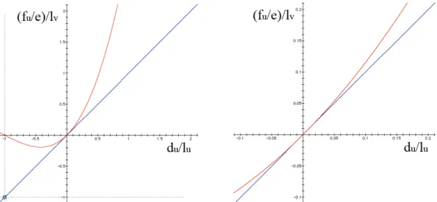
This approach is less “intuitive”, through the nonlinearity of their strain and stress tensors. Hence, their strain is not proportional to the deformation of the material, and the exerted force is not proportional to the stress. Actually, with stress linearly related to strain, the tensile force-deformation curve of such a material is rather cubic (Fig.2).
However, their mathematical definition is indeed the most mathematically “natural” way of expressing strain and stress, and indeed the simplest, despite the nonlinearity.
Figure 2: Tensile elongation force-deformation curve of a St.Venant-Kirchhoff material (red) compared to a linear material (blue), global view (left) and close-up (right). On the St.Venant-Kirchhoff material, we can note the “collapse” of the compression force for large compression
deformation.
However, the nonlinear native behavior of St.Venant-Kirchhoff materials has a significant adverse effect: Under large compression deformation, the tensile compression forces stop increasing, and even revert back to zero (Fig.2 left). Hence, these materials are prone to “collapse” under large compression, which makes them unsuitable for volume simulation [Bonet and Wood, 1997] [Irving et al, 2004]. This is indeed why these materials are usually overlooked in mechanical simulation systems, preferring linearized formulations instead.
Fortunately, this collapse behavior is usually not an issue in the context of cloth simulation: A cloth surface is almost never subject to large compression forces, since weak surface bending forces quickly allow compression to relax into buckling. Furthermore, the rapidly increasing tensile forces during extension are a much more realistic representation of the behavior of real fabric materials than a simple linear behavior.
Along this, the most attracting perspective of these materials is the simplicity of their formulation, ensuring efficient computation. Furthermore, they can easily be generalized for supporting arbitrary nonlinear strain-stress laws, for reproducing accurately the complex behavior of cloth materials through the weft, warp and shear deformation modes, a feature that most cloth simulation models lack, and that we intend to provide through this work.
1.3. Our Goal
Our ultimate goal is to be able to simulate very accurately complex cloth objects, such as complete garments on animated characters, with precise reproduction of the nonlinear mechanical behavior of cloth. Unlike what is possible to do with most existing cloth simulation models, we intend to reproduce accurately the nonlinear and anisotropic strain-stress behaviors, as discussed in Section 2.1, so as to match as closely as possible the actual behavior of cloth materials, particularly when it comes to large deformations. Our model should address elasticity as well as viscosity, making the model suitable not only for draping applications, but also for dynamic motion computations which require mechanical damping. We also want to perform the computation at a reasonable speed, possibly compatible with real-time or interactivity. Hence, we cannot afford models much more complicated than the simple spring-mass models which are typically used in this context.
Our new computation scheme should also support arbitrary triangle meshes which are typically generated from Delaunay triangulation. On these elements, we express strains and stresses according to the nonlinear Green- Lagrange tensors, also considering nonlinear strain-stress behaviors for representing accurately the nonlinear anisotropic behavior of cloth. Indeed, such use of continuum mechanics makes our scheme equivalent to classic tensile Finite Element schemes. However, we take advantage of its simplicity for formulating it in a very simple and direct Particle System approach, expressing particle forces directly from their positions. Furthermore, we formulate an accurate computation of the Jacobian, allowing high-performance simulation through efficient implicit integration methods or relaxation schemes which remain stable and robust even with very large deformations. All these developments are expressed without excessive abstract formalisms through “ready-to-implement” expressions allowing straightforward integration into computation algorithms. After some definitions on the mechanical behavior of cloth in Section 2.1, the computation scheme is detailed in Sections 2.2 and 2.3. We demonstrate the accuracy and efficiency of this scheme in Section 4.
The presented scheme only models tensile elasticity, which deals with in-plane deformations. Meanwhile, bending elasticity deals with out-of-plane deformations (surface curvature), and its main visible effect is to limit fold
curvature and wrinkle size. However, the resulting internal forces are comparatively very weak, and very often, wrinkle size is rather limited by the size of the surface elements, which often bring more bending rigidity than the actual physical bending stiffness. Therefore, it can often be ignored in the context of interactive cloth simulation using large elements and soft cloth materials. However, for high-accuracy simulations, the presented tensile model can easily be complemented by a bending model using the schemes defined by [Grinspun et al, 2003] or [Volino and Magnenat-Thalmann, 2006].
2. THE SIMULATION SCHEME 2.1. Tensile Viscoelasticity
From the theory of elasticity [Timoshenko and Goodier, 1970] [Gould, 1993], the internal tensile deformations of a surface are characterized by its strain, measured through a strain tensor, represented by three independent values εuu, εvv, εuv to the coordinate system of the material. In dynamic systems, their rate is measured though their time derivatives εuu’, εvv’, εuv’. Meanwhile, the internal tensile forces are characterized by its stress, measured accordingly though a stress tensor represented by three independent values σuu, σvv, σuv. The strain and stress values are related through the current energy per surface unit w of the material by the following relationships, for any deformation mode m among (uu,vv,uv):
m m
w σ ε
∂
= ∂
(1)The relationship between strain and stress defines the mechanical behavior of the material. In the most general context, this is expressed through the following strain-stress relationship:
( )
( )
(
uu vv uv uu vv uv)
uv
uv vv uu uv vv uu vv
uv vv uu uv vv uu uu
ε ε ε ε ε ε σ
ε ε ε ε ε ε σ
ε ε ε ε ε ε σ
′
′
′
′
′
′
′
′
′
, , , , ,
, , , , ,
, , , , ,
(2)
An isotropic material behaves exactly identically whatever its orientation, and its strain-stress relationship does not depend on the orientation of the considered coordinate system.
In the case of linear viscoelasticity, the strain-stress relationship can be expressed as a linear expression, the elastic and viscous stiffness of the material being represented as symmetric matrices E and E’:
⎥ ⎥
⎥
⎦
⎤
⎢ ⎢
⎢
⎣
⎡
′
′
′ + ′
⎥ ⎥
⎥
⎦
⎤
⎢ ⎢
⎢
⎣
⎡
=
⎥ ⎥
⎥
⎦
⎤
⎢ ⎢
⎢
⎣
⎡
uv vv uu
uv vv uu
uv vv uu
E E
ε ε ε ε
ε ε σ
σ σ
(3)
In the particular case of isotropic linear elasticity, the behavior of the material is only described with two parameters: The Young modulus e relates the stiffness of the material while the Poisson coefficient ν relates its transverse contraction upon extension (Fig.3). The corresponding matrix is the following:
⎥⎥
⎥⎥
⎦
⎤
⎢⎢
⎢⎢
⎣
⎡
− −
=
2 0 1 0
0 1
0 1
1 2
ν ν
ν ν
E e (4)
Figure 3: A square piece of cloth attached at two opposite edges (far left), extended at 150% of its initial length. The material is linear isotropic (4), with a Poisson coefficient ν of 0 (left), 0.25 (center), 0.50 (right). Colorscale shows transverse compression strain.
While isotropic materials are well adapted for simulating homogeneous materials, cloth materials are mostly made of fibers which are oriented along particular directions. Thus, they are very unlikely to exhibit the same stiffness whatever the deformation direction. Therefore, accurate representation of cloth materials require anisotropic models (Fig.4). Among them, orthotropic models, which assume stiffness symmetry along orthogonal fiber directions (symmetric radial stiffness diagram as in fig.4 far left), are only suited with cloth having orthogonal fiber orientations with symmetric weave patterns.
Figure 4: A large square piece of cloth cut along various fiber directions, hanging attached at one edge. The material is linear anisotropic (3), with 2 Euu,uu = 1 Evv,vv = 8 Euv,uv (radial elongation stiffness diagram far left). This represents typical anisotropy of cloth materials, which usually have a much lower shear/elongation stiffness ratio than isotropic materials. Strips show weft fiber direction. Colorscale shows average tensile strain.
Many simulation models exist for dealing with linear materials [Etzmuss et al, 2003]. However, through the complexity of its structures, cloth materials have very nonlinear behaviors: The internal deformations of the materials produce internal forces which are not at all proportional to them. Linear strain-stress models are a very rough approximation of the actual behavior of cloth materials, and they quickly show their limits for large deformations (as for instance, the “superelasticity” artifact observed by [Provot et al, 1995]) (Fig.5). Therefore, accurate cloth simulation requires nonlinear models for fitting closely the simulated cloth behavior to the actual one, usually measured through specific tensile tests (see Appendix). Our main interest is however to address the case of nonlinear materials through their most general strain-stress behavior (2), which is needed for representing accurately the large-scale behavior of structures which have high small-scale complexity, such as cloth.
Figure 5: A large square piece of cloth, hanging attached at two corners. The material is isotropic, with linear (left) (red curve far left) and nonlinear (right) (green curve far left) elongation strain-stress behavior. Colorscale shows average tensile stress (back) and strain (front). In both cases, there is a high concentration of stress around the attachment points which support the weight of the whole cloth. With a linear strain-stress behavior, this creates locally high strain, and therefore unrealistically large deformations in these areas. Meanwhile, a nonlinear strain-stress
behavior smoothes out the strain and the deformations are much more evenly distributed over the cloth.
While elastic forces oppose deformation, viscous forces oppose deformation rate. Viscosity does not affect the rest geometry of the cloth in static contexts (draping), but it contributes to the damping of the cloth motion through energy dissipation. Meanwhile, plasticity results from hysteresis in the stain-stress behavior of the material. It is quite significant for cloth materials, and it mainly results from the friction between the textile fibers. Like viscosity, the main noticeable effect of plasticity is also the cloth motion damping caused by energy dissipation.
Our model can be extended for modeling plasticity through an adequate processing of the strain-stress behavior.
The easiest solution, derived from [Breen et al, 1994] is to modify the rest strain of the strain-stress laws according to the current strain-stress state of the system, simulating the solid friction between the fibers. More advanced models, which take into account time-dependent evolution of the rest strain, could take advantage on models based on Prony series [Soussou et al, 1970]. However, a precise modeling of plasticity requires an accurate knowledge of the possibly time-dependent strain-stress behavior inside the hysteresis envelope (not only the envelope itself) and this requires measuring the tensile properties of the cloth materials with more sophisticated procedures than the
single load-unload cycle usually performed (Fig.6). The complete study of plasticity and its simulation is a topic on its own, far beyond the scope of this work. Furthermore, the numerical simulation is itself quite unpractical and very expensive due to the numerical problems caused by the high nonlinearity of hysteresis. This is why not many cloth simulation systems do actually support accurate simulation of plasticity.
Figure 6: Weft (left) and warp (right) elongation tensile test of a cloth material with several load-unload cycles of various amplitude. The precise evaluation of material plasticity requires a complex study of strain-stress hysteresis, far beyond the evaluation of the hysteresis envelope only.
While unnecessary in the context of cloth draping applications, the accurate dynamic reproduction of cloth motion along time requires significant damping for avoiding unrealistically “bouncing” materials. Whereas viscosity cannot be explicitly measured in cloth materials through simple and standard test procedures, it is nevertheless a simple solution for reproducing the global dissipative behavior caused by plasticity along viscosity. In this context, some techniques attempt to identify viscous parameters of cloth materials by experimentally matching the simulated damping of its motion to actual samples [Bhat et al, 2003].
In the following, we formulate our model for the context of general nonlinear anisotropic tensile viscoelasticity (2). Adequate simplifications may then be carried out according to the actual simulation context.
2.2. Computational Details
Our algorithm processes triangle elements of the mesh describing the surface (Fig.7 left). The mesh does not need to have grid regularity, and may be obtained on arbitrary surface regions by processes such as Delaunay triangulation. Each element is described by its 2D parametric coordinates (ua,va),(ub,vb),(uc,vc) of its vertices, referring to an orthonormal parametric coordinate system (in the context of cloth simulation, aligned to the weft and warp fiber directions). The current position of the deformed element is defined by the 3D world coordinates Pa,Pb,Pc
of its vertices, and possibly velocity coordinates P’a,P’b,P’c. The weft and warp vectors are expressed in 3D world coordinates as U and V, which are not necessarily orthonormal anymore because of material deformation (fig.7 right). In the following, these vectors will be used for measuring the deformation state of the element, as well as expressing any vector value related to the element in world coordinates.
U V
Weft Warp
Pa
Pb
Pc
(ua,va) (ub,vb)
(uc,vc)
Figure 7: A triangle element is defined in 2D parametric coordinates (left), and deformed in 3D world coordinates (right).
Our goal is to compute the deformation state of a triangle element directly from the positions of its vertices. For this, we express the parametric coordinates the weft and warp orthonormal vectors (1,0) and (0,1) as weighted sums of the parametric coordinates of the three vertices (ua,va), (ub,vb), (uc,vc), leading to the following linear systems:
∑
∑
∑
∑
∑
∑
=
=
=
=
=
=
i vi i vi i i vi i
i ui i ui i i ui i
r v r
u r
r v r
u r
0 1 0
0 0 1
(5)
Solving these linear systems leads to the following weights, to be precomputed:
( )
( )
( )
( )
( )
( )
a(
b c)
b(
c a)
c(
a b)
a b vc
c a vb
b c va
b a uc
a c ub
c b ua
v v u v v u v v u d u
u d r
u u d r
u u d r v
v d r
v v d r
v v d r
− +
− +
−
=
−
=
−
=
−
=
−
=
−
=
−
=
−
−
−
−
−
−
1 1 1
1 1 1
(6)
During the simulation, these values are the weights for computing the current 3D vectors U and V directly as a weighted sum of the current vertex positions Pi as follows:
∑
∑
∈∈
=
=
) , , ( )
, ,
( i abcvi i
c b a
i rui Pi V r P
U (7)
When viscosity has to be considered in the context of dynamic simulations, the current evolution rates of the coordinate vectors U’ and V’ can be computed as well from the current vertex velocities P’i:
∑
∑
∈∈
= ′
′
= ′
′
) , , ( )
, ,
( i abc
i vi c
b a i
i
ui P V r P
r
U (7’)
Our model is based on the Green-Lagrange strain tensor, which allows the rotation-invariant description of internal surface strain in the context of large displacements. This symmetric tensor G is defined by the coordinate vectors as follows, I being the identity matrix representing the rest state:
[ ] [ ]
(
U V U V I)
G = 21 T − (8)
From this tensor, we can extract the weft warp and shear strain values, which respectively measure the elongation deformations along weft warp directions and the shear deformation between them, as follows:
( )
( )
( V U V V V U )
U U
T T
uv
T vv
T uu
+
=
−
=
−
=
2 1 21 2 1
1 1 ε
ε ε
(9)
At this point, we can note that the strain is a quadratic expression of the vertex positions. We do not attempt to perform any linearization of these expressions.
Similarly, if viscosity is considered, the strain rate values are computed accordingly:
( )
( )
(
VU VV V U)
U U
T T
uv T vv
T uu
+ ′
= ′
′
= ′
′
= ′
′
ε ε ε
(9’)
Having computed the strain state of the triangle surface, we can now obtain the stress state by using the strain- stress relationship (2) that characterizes the material of the surface.
The Green-Lagrange strain tensor is associated to the second Piola-Kirchhoff stress tensor through (1).
Therefore, the forces Fj exerted on the vertex j is computed by derivation of the weft, warp and shear components of the total elastic energy W of the triangle relatively to the particle position Pj. Since we assume linear deformation of the triangle element, we have constant strain and stress and therefore surfacic energy w over its surface of area |d|/2 (6), and we have, for any j among (a,b,c):
⎟⎟
⎠
⎞
⎜⎜
⎝
⎛
⎟⎟
⎠
⎞
⎜⎜
⎝
⎛
∂
− ∂
∂ =
− ∂
∂ =
−∂
=
∑
∈( , , )
2
2 m uuvvuv
T
j m m T
j T
j
j P
d P
d w P
F W
σ ε
(10)With explicit expression of the derivatives of the Green-Lagrange strain values (9) using (7), we obtain:
( ) ( ) ( )
( r U r V r V r U )
F
j= − d σ
uu uj+ σ
vv vj+ σ
uv uj+
vj2
(11)Direct implementation of (7), (9), (2), (11) can be the basis of an accurate Particle System model integrated with explicit numerical methods, such as Runge-Kutta [Eberhardt et al, 1996].
2.3. Computing the Jacobian
The Jacobian of the forces is necessary for implementing implicit numerical integration methods [Baraff and Witkin, 1998] [Eberhardt et al, 2000] [Hauth et al, 2001] [Volino et al, 2005], and any other relaxation schemes based on Newton iterations. Its accurate evaluation is necessary for good convergence and stability of state-of-the- art simulation systems.
This Jacobian is computed from (10) and (2) as follows, for any i and j among (a,b,c):
⎟⎟
⎟
⎠
⎞
⎜⎜
⎜
⎝
⎛
⎟⎟
⎠
⎞
⎜⎜
⎝
⎛
∂
∂
∂ + ∂
⎟⎟
⎠
⎞
⎜⎜
⎝
⎛
∂
∂
∂
∂
∂
− ∂
∂ =
∂
∑ ∑
∈∈ ∈( , , )
) , , (( , , )
2 m uuvvuv
T
j m i m uv
vv uu n uuvvuv
m i
n T
j m n m i
j
P P P
P d
P
F
ε ε σ ε
ε
σ
(12)Considering viscosity, the following contribution has to be considered as well:
⎟ ⎟
⎟
⎠
⎞
⎜ ⎜
⎜
⎝
⎛
⎟ ⎟
⎠
⎞
⎜ ⎜
⎝
⎛
∂
∂
∂
∂
∂ ′
− ∂
′ =
∂
∂ ∑
∈∈ ) , , (( , , )
2
uv vv uu n uuvvuv
m i
n T
j m n m i
j
P P d
P
F ε ε
ε
σ
(12’)With explicit expression of the derivatives of the Green-Lagrange strain values (9) using (7), we obtain (for simplicity, here written without the contributions of the cross-dependencies between the deformation modes):
( ) ( ) ( )
( ) ( ) ( )
( )
⎟⎟⎟
⎠
⎞
⎜⎜
⎜
⎝
⎛
+ +
+ +
∂ + +∂
∂ +∂
∂
∂
−
∂ =
∂
I r r r r r
r r
r
U V r r V U r r V
V r r U
U r d r
P F
ui vj vi uj uv vi vj vv ui uj uu
T ui vj T vi uj uv
uv T
vi vj vv
vv T
ui uj uu
uu
i j
σ σ
σ
ε σ ε
σ ε
σ
2 (13)
Considering viscosity:
( ) ( ) ( )
⎟⎟⎠
⎜⎜ ⎞
⎝
⎛ +
∂ ′ +∂
∂ ′ +∂
∂ ′
− ∂
′ =
∂
∂ T
ui vj T vi uj uv T uv
vi vj vv T vv
ui uj uu uu i
j d r r UU r r VV r r UV r r V U
P F
ε σ ε
σ ε
σ
2 (13’)
This Jacobian, which is globally symmetric thanks to the symmetric strain-stress laws (2), has a fairly simple structure, and the numerical solving algorithm should take advantage of this for numerical solving or sparse storage.
The expression of the elasticity Jacobian (12) (13) has two components:
* A stiffness component, which depends on the strain-stress stiffness ∂σ/∂ε.
* A geometric component, which depends on the stress value σ.
The expression of the viscosity Jacobian (12’) (13’) has only a stiffness component.
It can be noted that in the context of linear viscoelasticity (3), the terms ∂σ/∂ε and ∂σ/∂ε’ and are simply the elements of the elastic stiffness matrices E. and E’.
The stiffness component represents how the strain-stress stiffness of the material acts in the relationship between particle forces and positions. It is usually the most important component of the Jacobian. Meanwhile, the geometric component represents the particle force changes which result only from the evolution of the element geometry. For instance, it relates the rotation of the particle forces as the element rotates.
In the context of small deformations, it would make sense to ignore the geometry component of the Jacobian, assuming that the vectors U and V do not evolve far from their initial state. This is typically the approach done in approaches which use a linear approximation of the Green-Lagrange tensor, possibly addressing larger deformations through the corotational approach [Etzmuss et al, 2003]. However, as pointed out by [Choi and Ko, 2002] in the context of spring-mass systems, the full evaluation of the Jacobian is important for the stability of the simulation in
the context of large deformations such as cloth simulation, where elements may exhibit large orientation changes within few iterations. Fortunately, through the use of the simple, non-linearized expression of the Green-Lagrange tensor, the expression of the geometric component is quite simple, and furthermore isotropic (it does not directly depend on the current values of U and V). Therefore, this approach is the best for performing stable simulations of highly deformable nonlinear materials through the use of a Jacobian accurately matching the actual deformed state of the mechanical system, whatever the amount of deformation (Fig.8).
Figure 8: An accurate Jacobian is necessary for stable simulation of very large deformations without compromising convergence speed.
A potential problem related to this expression results from the possible negative eigenvalues that the isotropic Jacobian component might introduce in numerical linear system matrix of the integration scheme. While this is not an problem in the context of the accurate linear system solving schemes used in most Finite Element models, this could potentially bring trouble if the Conjugate Gradient method is used, such as with most implicit Particle System integration methods. There is no much worry to have about this concerning the stiffness component, where positive eigenvalues are ensured by the physical plausibility of the material (where usually forces monotonously oppose deformations). However, the geometric component is more likely to generate negative eigenvalues, particularly when material compression state creates negative eigenvalues in the stress tensor. While, in the context of cloth simulation, this is not much an issue as surface buckling quickly absorbs large tensile compression, this still needs to be addressed for obtaining an instability-proof simulation system (transitionally highly compressed elements can always occur during simulation). While filtering out negative eigenvalues from the global Jacobian is not a computationally practical option, a formal, fairly conservative solution would be to filter out the negative eigenvalues of the stress tensor through adequate projection of the σuu, σvv, σuv values to be used in the computation of the geometric component (similarly to what [Choi and Ko, 2002] does with spring-mass systems). In practice, we have experimented that a sufficient approximation for ensuring stability is to use null values of σuu or σvv if they are negative, thus avoiding any eigensystem computation.
2.4. Algorithm Summary
The simple computational process can directly be formulated in a ready-to-implement manner through the Particle System formalism, summarized as follows:
Precomputation
* On each element, evaluate and store the vertex distribution factors using (6):
Computation
* On each element, evaluate the current material referential U and V from Pa, Pb, Pc using (7).
* From this, compute the strain values εuu, εvv, εuv using (9).
* And compute the stress values σuu, σvv, σuv using the mechanical behavior of the material (2).
* Then compute the corresponding particle force contributions Fa, Fb, Fc using (11).
* If needed, compute the Jacobian contribution using (13) with the partial derivatives of (2).
3. CONSIDERATIONS
3.1. St.Venant-Kirchhoff Materials
Considering a linear strain-stress relationship (3), the material is a hyperelastic St.Venant-Kirchhoff material, which has a cubic tensile force-deformation relationship (Fig.2). This nonlinear behavior is indeed much more representative of the nonlinear tensile behavior of usual cloth materials than a linear tensile force-deformation behavior.
The largest interest of such a model is the simplicity of its computation, and the computation of (7), (9), (11), (13) can also be carried out with additions and multiplications only, without the need of square roots (no vector normalizations) or trigonometry (no coordinate rotations). Hence, it is possible to implement a very simple simulation system suited for real-time or interactive applications. Furthermore, there are also no discontinuities or singular configurations, and this makes such model very appropriate for robust interactive systems.
3.2. Mass Lumping
In our Particle System scheme, the mass given to each particle should be exactly one third of the mass of all triangle elements adjacent to that particle in the mesh. Obviously, the mass of an element is the surfacic mass of the cloth material times the area |d|/2 of the triangle.
A significant difference between Finite Elements and Particle Systems is that while the former considers accurately the mass of the mechanical system distributed over the surface of the elements, the latter condensates the mass of the elements on the discrete particle locations. Hence, the mass of a uniform triangle element is distributed equally on its three vertices. As a side effect, the rotational inertia of the element around its mass center becomes four times larger. In most contexts however, this is not a significant issue since the rotational inertia of small
elements is usually not significant compared to their translational inertia. As a major benefit of this approximation, the inertia matrix only contains diagonal elements, and this drastically simplifies the mechanical computations. This is why this approximation, known as mass lumping, is also often considered in usual Finite Element models.
4. PERFORMANCE
This model has been integrated in a cloth simulation system that allows interactive editing of cloth objects and collision processing, for the creation and simulation of complete garments.
In our implementation, the mechanical model accepts independent weft, warp and shear elastic strain-stress curves modeled as polynomial splines of any order. Possible cross-dependencies among these modes are also accepted by our system, for instance modeling transverse contraction. Viscosity is also modeled in the same way.
External forces include gravity, anisotropic viscous aerodynamic drag (wind) and collision effects (friction).
The Particle System is integrated with Backward Euler, Implicit Midpoint [Volino and Thalmann, 2005] or alternatively BDF-2 [Hauth et al, 2001] numerical integration methods for performing dynamic cloth simulations.
Meanwhile, for cloth relaxation and draping applications, an iterative Newton resolution scheme which finds the particle positions that minimize the particle forces through the Jacobian was also implemented. In any of these implicit schemes, our implementation uses, for each iteration, the Jacobian of the forces corresponding to the actual current state of the system. This variable Jacobian scheme, which captures accurately all the nonlinearities of the system, is made possible through on-the-fly evaluation of the Jacobian directly inside the numerical solving of the computation iteration, which is performed using the Conjugate Gradient method.
The computation code is written in standard C++ using double precision floating-point, and the tests are performed on a 3GHz Pentium4 PC.
4.1. Accuracy of the Model
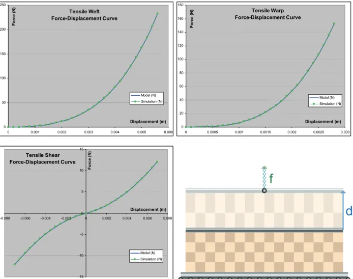
Our accuracy test consists in simulating a virtual material described by its weft, warp and shear nonlinear strain- stress curves, modeled from force-displacement curves of a tensile test. Through simulation, we perform a virtual tensile test of the material, comparing the resulting force-displacement curves to the experimental ones.
We have performed this test using a 150g/m2 wool gabardine fabric, which is a fairly nonlinear material, highly anisotropic with weak shear stiffness.
We have first measured the tensile weft, warp and shear (along weft) force-elongation curves using a tensile tester on the normalized 20cm×5cm sample. The averages of the load and unload curves, once converted into strain- stress curves according to the formula given in the Appendix, are then modeled with polynomial splines (3 segments, 3rd-order for elongation and 2nd-order for shear).
The virtual simulation of the experimental setup has then been carried out on a virtual sample of 2500 triangles:
The cloth rectangle is attached along its two longest edges, and the total attachment force along one edge is
measured according to its displacement. No other external force is considered and gravity is set to 0. Between each state change, the cloth equilibrium was computed using the Newton relaxation method.
The following force-displacement curves give the comparison between the polynomial model modeling the experimental data and the virtual test data (strain-stress curves converted back to force-displacement curves) (Fig.9).
Tensile Weft Force-Displacement Curve
0 50 100 150 200 250
0 0.001 0.002 0.003 0.004 0.005 0.006
Displacement (m)
Force (N)
Model (N) Simulation (N)
Tensile Warp Force-Displacement Curve
0 20 40 60 80 100 120 140 160 180
0 0.0005 0.001 0.0015 0.002 0.0025 0.003
Displacement (m)
Force (N)
Model (N) Simulation (N)
Tensile Shear Force-Displacement Curve
-15 -10 -5 0 5 10 15
-0.008 -0.006 -0.004 -0.002 0 0.002 0.004 0.006 0.008
Displacement (m)
Force (N)
Model (N) Simulation (N)
d f
Figure 9: Comparing simulated weft, warp and shear force-displacement curves with their counterparts defined in the model. With less than 0.01% difference, the curves are practically identical. The virtual tensile setup is shown at bottom right.
From these curves, we can see that the force-displacement behavior our simulation system duplicates very precisely the force-displacement model resulting strain-stress polynomial spline model (converted back to force- displacement). The error remains always below 0.01%, with force differences below 0.01 N whereas total forces may exceed 100 N.
This illustrates the very high accuracy that our model can provide even in the context of nonlinear anisotropic materials in the context of large deformations. Such accuracy is indeed expected, since our model represents accurately the mechanical constitutive laws of the material model through continuum mechanics without any
approximation. Furthermore, since the computation of the Jacobian is also exact, the model converges fairly quickly to the theoretical value described by the curve model (in less than 10 iterations to the error specified above, and only limited by the numerical floating-point accuracy of the computations).
4.2. Real-World Accuracy
In order to verify the validity of our model for simulating cloth in a more “real-world” context, we have set-up an experiment for comparing the behavior of the real cloth with the simulated virtual cloth.
A piece cloth is clamped horizontally on a circular frame (30cm diameter), with as little initial tension as possible. Then, a vertical force is exerted on a disk (6cm diameter) on the middle of the cloth. The vertical displacement of the disk is measured according to that force (Fig.10). We have chosen a fairly soft terry cloth, so as to observe fairly large displacements that can be accurately measured.
For the real tests, we have performed an average of several measurement sequences, which allow us to assess the accuracy of these measurements through the computation of the standard deviation. Observed measurement variations (around 10%) would mainly result from variations of the initial tension of the cloth on the frame, as well as some possible material plasticity effects of the material between each measurement. For the simulation, strain- stress curves have been measured accurately using tensile tests (as described in the Appendix), modeled as three independent (weft, warp, shear) polynomial splines (14) averaging the hysteresis loop, and implemented in our simulation system.
Force / Displacement Curves
0 0.5 1 1.5 2 2.5 3
0 10 20 30 40 50 60
Displacement (mm)
Force (N)
Simulated Measured
Figure 10: The experimental setup (top), and the virtual simulation (bottom left). Depending on the force exerted by the weight on the middle of the cloth, the vertical displacement is plotted (bottom right), comparing the simulation (green curve) with the average of several experimental
measurements (red dots with error bars showing average deviation).
The measured curve (Fig.10 bottom right) shows that our simulation can reproduce the real cloth with a fairly good accuracy. Along inaccuracy causes mentioned above, another could be the approximate modeling of the material, not taking into account possible dependencies between weft warp and shear deformation modes, as discussed in the Appendix.
4.3. Computation Time
Computational timings were performed on the dynamic simulation of a 1m×1m cloth square (Fig.11), initially horizontal, attached along one of its edges. Numerical integration was performed using the Inverse Euler integration, with constant simulation timesteps of 10 milliseconds.
For comparison, we have implemented in our simulation system the linearized corotational scheme, obtained by rotation of the local element coordinates to the eigendirections of the strain tensor and linearization of the strain and stress expressions. It can be noted that the expression of the Jacobian is more complex (because of the linearization) and requires approximations (because of the state-dependent rotation).
We have compared the computation time of our scheme and the linearized corotational scheme for computing 100 timesteps of the computation with several mesh resolutions. The considered material is a simple isotropic
material (3) (4) of Young modulus e = 1000 N/m, null Poisson coefficient ν = 0. We have also compared the computation time of a simple spring-mass system (springs defined along mesh edges) having an equivalent stiffness.
Computation Time for 100 iterations
0 50 100 150 200 250 300 350 400 450
0 5000 10000 15000 20000 25000 30000
Element Count
Time (s)
Linearized Corot.
Non-Linearized Spring-Mass
Figure 11: Computation times required for the iterating the computation of 1m2 of cloth, using various mesh resolutions, using our simulation scheme, the linearized corotational scheme and a simple spring-mass scheme.
From these curves, we can see that our implementation of the model is able to iterate more than 17 500 elements per second. Meanwhile, the linearized corotational scheme is about two times slower. This slowdown results not only from the computation of the eigensystem for evaluating the rotation, but also from the additional coordinate rotations done in the computation. Furthermore, using a linearized scheme also requires additional vector normalisations (square roots), as well as a more complex, non-isotropic geometric component in the exact expression of the Jacobian (13). It should be noted that the numerical solving process (involving usually between 10 and 15 iterations of the Conjugate Gradient algorithm for each timestep, depending on the stiffness) also accounts for more than half of the total computation time.
The interesting point is that the simple spring-mass system is only marginally faster compared to our scheme, with only 20 000 elements iterated per second. Hence, our simulation scheme offers a huge increase of simulation accuracy for only about 15% additional computation.
Tested in the same conditions with our simulation scheme, the nonlinear anisotropic strain-stress behavior defined is the previous section requires roughly 10% additional computation.
4.4. Application: Virtual Prototyping
The presented model has been implemented in a virtual prototyping system which allows the design of complex garments on mannequins. The efficiency of the model allows the simulation of the accurate mechanical properties of cloth on high-resolution meshes as the mannequin moves, allowing the garment designer to assess the stretch forces for particular postures (Fig.12). The design of the garment patterns may then be corrected accordingly, with
interactive mechanical feedback on the garment drape. The Particle System approach allows complex multilayer garments to be processed through an adequate handling of complex collision situations. Through the use of various implicit integration schemes, the model can efficiently compute both static drapes and dynamic animations.
Figure 12: Virtual prototyping applications require an accurate representation of cloth material behavior for evaluating precisely the stretch forces (color scale) on the garment along particular postures of the character (top). An efficient simulation model is also required for the dynamic
simulation of high-resolution complex garments involving several layers of cloth.
5. CONCLUSION
Through the presented computation scheme, we have obtained an accurate simulation system which offers high- accuracy representation of cloth deformation based on continuum mechanics. Through the use of the non-linearized Green-Lagrange tensor, this system performs the simulation of hyperelastic St.Venant-Kirchhoff materials, which are particularly adapted for representing the behavior of cloth materials. Yet, this scheme is also extended for supporting accurately nonlinear and anisotropic representations of weft, warp and shear strain-stress curves, which can be obtained from force-deformation curves measured with traditional tensile tests on actual fabric samples.
The presented scheme is one of the simplest available featuring the accuracy of continuum mechanics. It remains accurate for large deformations without the need of complicating the computation process with additional transformations, such as corotational formulations. Furthermore, it can be expressed as a classical Particle System (with particle forces directly computed from particle positions), offering a high versatility of applications in numerous simulation contexts (draping, dynamic simulation, collision response and other geometric constraints, etc). The exact Jacobian of the model can also be efficiently computed, offering efficient and stable simulations through the use of implicit integration methods (Inverse Euler, BDF-2, etc).
Through these qualities, this simulation scheme is particularly well adapted for applications that need to combine good mechanical accuracy with computation times compatible with interactive applications. It is therefore a very good candidate for garment prototyping applications.
The highly streamlined computational process also opens the doors for parallelization and hardware implementation, which, through the rise of dedicated chips, represent the future of high-performance mechanical simulation.
ACKNOWLEDGEMENTS
We are grateful to all MIRALab team who participated to this research through their contributions, advices, testing and creative artwork. Special thanks for Christiane Luible for her expertise in garment design and animation. This research is funded by the European FP6 project LEAPFROG IP (NMP2-CT-2005-515810).
BIBLIOGRAPHY
D.BARAFF,A.WITKIN, 1998, Large Steps in Cloth Simulation, Computer Graphics (SIGGRAPH’98 proceedings), ACM Press, pp 43-54.
J.BARBIC,D.L.JAMES, 2005, Real-Time Subspace Integration for St.Venant-Kirchhoff Deformable Models, ACM Transactions on Graphics (ACM SIGGRAPH 2005 proceedings).
K.S..BHAT,C.D.TWIGG,J.K.HODGINS,P.K.KHOSLA,Z.POPOVIC,S.M.SEITZ, 2003, Estimating Cloth Simulation Parameters from Video, Proceedings of SIGGRAPH-Eurographics Symposium on Computer Animation 2003, pp 37-51.
K.JBATHE, 1982, Finite Element procedures in engineering analysis, Prentice Hall.
G.BIANCHI,B.SOLENTHALER,G.SZÉKELY,M.HARDERS, 2004, Simultaneous Topology and Stiffness Identification for Mass-Spring Models Based on FEM Reference Deformations, Medical Image Computing and Computer-Assisted Intervention proceedings, C. Barillot, 2, pp 293-301.
J.BONET,R.WOOD, 1997, Nonlinear Continuum Mechanics for Finite Element Analysis, Cambridge University Press, Cambridge.
D.BOURGUIGNON D,M.P. CANI, Controlling Anisotropy in Mass-Spring Systems, Eurographics Workshop on Computer Animation and Simulation, pp 113-123.
D.E. BREEN, D.H. HOUSE, M.J. WOZNY, 1994, Predicting the Drape of Woven Cloth using Interacting Particles, Computer Graphics (SIGGRAPH’94 proceedings), Glassner, pp 365-372.
M.BRO-NIELSEN,S.COTIN, 1996, Real-Time Volumetric Deformable Models for Surgery Simulation using Finite Elements and Condensation, Eurographics 1996 proceedings, ACM Press, pp 21-30.
K.J.CHOI,H.S.KO, 2002, Stable but Responsive Cloth, Computer Graphics (SIGGRAPH’02 proceedings), Addison Wesley, pp 604-611.
S.COTIN,H.DELINGETTE,N.AYACHE, 1999, Real-Time Elastic Deformations of Soft Tissues for Surgery Simulation, IEEE Transactions on Visualization and Computer Graphics, 5(1), pp 62-73.
M.DESBRUN,P.SCHRÖDER,A.H.BARR, 1999, Interactive Animation of Structured Deformable Objects, Proceedings of Graphics Interface, A K Peters, pp 1-8.
G.DEBUNNE,M.DESBRUN, M.P.CANI,A.H. BARR, 2001, Dynamic Real-Time Deformations Using Space & Time Adaptive Sampling, Computer Graphics (SIGGRAPH’01 proceedings), Addison Wesley, pp 31-36.
B.EBERHARDT,A.WEBER,W.STRASSER, 1996, A Fast, Flexible, Particle-System Model for Cloth Draping, Computer Graphics in Textiles and Apparel (IEEE Computer Graphics and Applications), IEEE Press, pp 52-59.
B.EBERHARDT,O.ETZMUSS,M.HAUTH, 2000, Implicit-Explicit Schemes for Fast Animation with Particles Systems, Proceedings of the Eurographics workshop on Computer Animation and Simulation, Springer-Verlag, pp 137-151.
J.W.EISCHEN,S.DENG,T.G.CLAPP, 1996, Finite Element Modeling and Control of Flexible Fabric Parts, Computer Graphics in Textiles and Apparel (IEEE Computer Graphics and Applications), IEEE Press, pp 71-80.
O.ETZMUSS,J.GROSS,W.STRASSER, 2003, Deriving a Particle System from Continuum Mechanics for the Animation of Deformable Objects, IEEE Transactions on Visualization and Computer Graphics, IEEE Press, pp 538-550.
O.ETZMUSS, M.KECKEISEN, W.STRASSER, 2003, A Fast Finite Element Solution for Cloth Modeling, Proceedings of the 11th Pacific Conference on -Computer Graphics and Applications, pp 244-251.
P.GOULD, 1993, Introduction to Linear Elasticity, 2nd edition, Springer.
E.GRINSPUN,A.H.HIRANI,M.DESBRUN,P.SCHRÖDER, 2003, Discrete Shells, Eurographics Symposium on Computer Animation, pp 62-68.
M.HAUTH,O.ETZMUSS, 2001, A High Performance Solver for the Animation of Deformable Objects using Advanced Numerical Methods, Eurographics 2001 proceedings, pp 137-151.
M.HAUTH,J.GROSS,W.STRASSER, 2003, Interactive Physically-Based Solid Dynamics, Eurographics Symposium on Computer Animation, pp 17-27.
M.HAUTH,W.STRASSER, 2004, Corotational Simulation of Deformable Solids, WSCG 2004 proceedings, pp 137-145.
G.IRVING,J.TERAN,R.FEDKIW, 2004, Invertible Finite Elements for Robust Simulation of Large Deforma