HAL Id: tel-00541140
https://tel.archives-ouvertes.fr/tel-00541140
Submitted on 29 Nov 2010
HAL is a multi-disciplinary open access archive for the deposit and dissemination of sci- entific research documents, whether they are pub- lished or not. The documents may come from teaching and research institutions in France or abroad, or from public or private research centers.
L’archive ouverte pluridisciplinaire HAL, est destinée au dépôt et à la diffusion de documents scientifiques de niveau recherche, publiés ou non, émanant des établissements d’enseignement et de recherche français ou étrangers, des laboratoires publics ou privés.
To cite this version:
Frédéric Mallet. Temps Logique pour l’ingénierie dirigée par le modèles. Modeling and Simulation.
Université Nice Sophia Antipolis, 2010. �tel-00541140�
UNIVERSIT´ E NICE-SOPHIA ANTIPOLIS
Ecole Doctorale STIC ´
Habilitation ` a Diriger des Recherches
Sp´ ecialit´ e: INFORMATIQUE par
Fr´ ed´ eric MALLET
Logical Time in Model-Driven Engineering
Soutenue publiquement le 26 novembre 2010 devant le jury compos´ e de:
Rapporteurs M. Robert France Professor CSU
M. Suzanne Graf DR CNRS/HDR
M. Jean-Pierre Talpin DR INRIA/HDR Pr´ esident M. Fran¸ cois Terrier DR CEA/Professor Examinateurs M. Charles Andr´ e Professor UNS
M. Robert de Simone DR INRIA/HDR
Laboratoire I3S, salle de conf´erences
Preface
In this document, I introduce some work realized over the last few years in col- laboration with the team-project Aoste and other people with various backgrounds.
AOSTE is a joint team between I3S and INRIA, bi-localized in Sophia Antipolis and Rocquencourt. It builds on previous experience by research scientists from the former TICK and OSTRE INRIA teams, and the I3S SPORTS team from the University of Nice-Sophia antipolis. Aoste tackles several topics in the design methodologies for real-time embedded systems. Here design means altogether:
High-Level Modeling ;
Transformation and Analysis ;
Implementation onto Embedded platforms.
To cover this vast spectrum of subjects we need to specialize the type of formalisms considered. Aoste focuses on synchronous reactive systems, such as Esterel/SyncCha- rts, and on the AAA methodology. Part of our activity is devoted to enrich the Model Based Design approach with a proper uml modeling diagrams and profiles with el- ements allowing for efficient modeling and embedding of synchronous designs. The main idea was to extend the Unified Modeling Language (uml) so as it could be used for the design of embedded and real-time systems. uml provides a broad range of diagrams to cover all aspects of a system (e.g., requirements, object models, func- tional models, state machines, data flows, deployment). It allows extensions through the definition of profiles and seems to be a good front-end to capture models. These models need a precise semantics and depending on the analysis context the same
i
rather be made explicit within the model.
Following some collaborations with the CEA-List and Thal`es Research & Tech- nology, we have had the opportunity to contribute to the definition of theumlprofile for Modeling and Analysis of Real-Time and Embedded systems (marte) by the Object Management Group (omg). The main part of this contribution was to lead the definition of its model and allocation models. Inspired by our background in synchronous reactive systems, we setup in 2005 to define a language, called the Clock Constraint Specification Language (ccsl), as a support to make explicit the causal and chronological relations between events of a system. Even though it was devised as a companion language foruml/martemodels, ccslhas been developed indepen- dently and is now defined as a model (rather than a language) that can complement not only umlmodels but also non-uml ones (e.g., ecore-based).
The first part of this document describes ccsl. The remaining two parts give usage examples of ccslfor modeling (Part II) and for verification (Part III).
ii
Acknowledgement
I must say that, as most research works, this work would not have been possible without the help and contribution of several administrative, engineering and research staff and students. So I want to thank every one that felt concerned by this work at some point or another.
I am greatly in debt to the referees and members of my examination committee.
In a time where the administrative duties are overwhelming I know how demanding it may be to read and report on dissertations. I am grateful that they took some of their time to do it for me and to be part of my committee.
I also want to thank the Aoste team members, current and paste, for being good sparring partners and our assistants for helping me through the administrative maze.
Special thanks to Charles, for his great work in defining ccsl, for his huge contribu- tion to this work and for having always been very helpful and ready to discuss. Many thanks to Robert for, as team leaders should do, providing the resources required to foster research activity (research tracks, fundings and collaboration partners).
I have special thoughts for Fernand who has followed my work since the begin- ning of my Master. He has been of a great support to decrypt and synthesize the tremendous work of philosophers and physicists who have, for ages, tried to grasp the essential nature of time.
To my parents, To Iris, To Luc & Vincent.
iii
Preface i
Acknowledgement iii
I Logical Time at/as design time 1
1 Background 3
1.1 Models of Computation and Communication . . . 3
1.2 Events, causality, exclusion . . . 6
1.3 Tag structures . . . 8
1.4 Logical time and logical clocks . . . 11
2 The Clock Constraint Specification Language 13 2.1 Instants, clocks and time structures . . . 13
2.2 Clock constraints . . . 16
2.2.1 Coincidence-based clock constraints . . . 16
2.2.2 Derived coincidence-based clock constraints . . . 17
2.2.3 Precedence-based clock constraints . . . 18
2.2.4 Derived precedence-based clock constraints . . . 19
2.2.5 Mixed constraints . . . 20
2.2.6 TimeSquare . . . 22
2.3 UML for Real-Time and Embedded systems . . . 23 iv
2.3.1 UML, SPT, Marte . . . 23
2.3.2 Marte Time profile . . . 25
2.3.3 UML and formal methods . . . 27
2.3.4 UML and synchronous languages . . . 28
2.3.5 SysML/Marte . . . 29
2.4 The future of MARTE Time Model . . . 31
3 How does CCSL compare ? 33 3.1 Petri Nets . . . 34
3.1.1 Time Petri nets . . . 34
3.1.2 Encoding CCSL operators in Time Petri nets . . . 35
3.2 Process networks . . . 38
3.2.1 Synchronous Data Flow . . . 38
3.2.2 A CCSL library for SDF . . . 39
3.2.3 Discussion and perspectives . . . 40
3.3 Polychronous languages . . . 42
3.3.1 Signal . . . 42
3.3.2 Encoding CCSL operators in Signal . . . 43
3.3.3 Hierarchization of CCSL clock constraints . . . 47
3.4 Perspectives . . . 48
II Modeling 51
4 The automotive domain 53 4.1 An ADL for automotive software: East-ADL2 . . . 534.1.1 Timing Requirements . . . 54
4.1.2 Example: An ABS controller . . . 56
4.2 A CCSL library for East-ADL . . . 57
4.2.1 Applying the UML profile for Marte . . . 57
4.2.2 Repetition rate . . . 58
4.2.3 Delay requirements . . . 59 v
5 The avionic domain 63
5.1 Architecture & Analysis Description Language . . . 64
5.1.1 Modeling elements . . . 64
5.1.2 AADL application software components . . . 64
5.1.3 AADL execution platform components . . . 65
5.1.4 AADL flows . . . 65
5.1.5 AADL ports . . . 66
5.2 From AADL to UML Marte . . . 66
5.2.1 Two layers or more . . . 66
5.2.2 AADL application software components . . . 68
5.2.3 Modeling ports . . . 69
5.3 Describing AADL models with Marte . . . 69
5.3.1 AADL flows with Marte . . . 69
5.3.2 Five aperiodic tasks . . . 71
5.3.3 Mixing periodic and aperiodic tasks . . . 72
5.4 Perspectives . . . 74
III Verification 75
6 Building language-specific observers for CCSL 77 6.1 The generation process . . . 776.2 Adapters . . . 80
6.2.1 In Esterel . . . 80
6.2.2 In VHDL . . . 80
6.3 Relation observers . . . 81
6.3.1 In Esterel . . . 82
6.3.2 In VHDL . . . 82
6.4 Generators . . . 83 vi
6.4.1 In Esterel . . . 84
6.4.2 In VHDL . . . 85
6.5 Perspectives . . . 86
7 Verifying Esterel implementations 87 7.1 Example: a digital filter . . . 87
7.2 CCSL specification . . . 88
7.3 Running simulations with TimeSquare . . . 91
7.4 Analysis with Esterel observers . . . 92
8 Verifying VHDL implementations 95 8.1 Example: an AMBA AHB to APB Bridge . . . 95
8.2 CCSL specification . . . 96
8.3 Analysis with VHDL observers . . . 99
IV Conclusion 103
Bibliography 106
vii
1.1 Exclusion in occurrence nets and event structures . . . 6
1.2 Causality and exclusion . . . 7
1.3 Enabling and consistency. . . 8
1.4 Tag structure by example . . . 10
1.5 Logical clocks by example . . . 10
2.1 Graphical representation of instant relations . . . 15
2.2 Coincidence-based clock constraint . . . 17
2.3 Precedence-based clock constraint . . . 19
2.4 Sampling constraints . . . 21
2.5 SysML parametric diagrams . . . 30
3.1 Precedence and alternation in Time Petri net . . . 35
3.2 B isPeriodicOn A period=P offset=δ . . . 36
3.3 Operator defer: B = A$C 2 . . . 37
3.4 CCSL alternatesWith encoded as an automaton . . . 43
4.1 The metamodel of East-ADL Timing Requirements. . . 55
4.2 Timing requirements for the ABS . . . 56
4.3 Example of the ABS . . . 57
4.4 Executing the east-adl specification of the ABS with timesquare . . 60
5.1 The example in AADL . . . 64
5.2 Three-layer approach with Marte . . . 67
5.3 A UML/Marte library for AADL threads . . . 68 viii
5.4 End to end flows with UML Marte . . . 70
5.5 AADL thread activation conditions denoted as CCSL clocks . . . 71
5.6 Five aperiodic tasks. . . 71
5.7 Mixing periodic and aperiodic tasks. . . 73
6.1 The observation network structurally reflects the ccslmodel . . . 79
7.1 Some time constraints on the DF behavior . . . 89
7.2 Pixel dependency . . . 90
7.3 One acceptable solution generated by TimeSquare . . . 92
8.1 A typical write transfer through the bridge . . . 97
8.2 Sample Execution of Constraint 3 on CCSL Simulator . . . 100
ix
Part I
Logical Time at/as design time
1
ccslhas arisen from different inspiring models in an attempt to abstract away the data and the algorithms and to focus on events and control. Even though ccsl was initially defined as the time model of the umlprofile for marte, it has now become a full-fledged domain-specific modeling language for capturing causal, chronological and timed relationships. It is intended to be used as a complement of other syntactic models that capture the data structure, the architecture and the algorithm.
Chapter 1 introduces the background and the historical models of concurrency that have inspired the construction of ccsl. Chapter 2 introduces ccsl and its relationships to theumlandmarte. Chapter 3 comparesccslto related concurrent models.
Chapter 1 Background
1.1 Models of Computation and Communication
Embedded systems are built by assembling various kinds of concurrent components : hardware or software. For hardware components, the concurrency is physical be- cause components actually run in parallel; hardware description languages consider components as concurrent processes that communicate through shared signals. Em- bedded software is increasingly a composition of concurrent processes and departs from traditional software engineering by making explicit the concurrency and by of- fering mechanisms to model the time. For software components, the concurrency is potential and mainly due to the dependency or rather independence between data (and control) processed by algorithms. In both cases, the components interact in a va- riety of ways, not limited to the simple transfer of control of the classical synchronous message-passing mechanism predominantly used in software engineering. Compo- nents represent computations (or communications) and their interaction are governed by so-called Models of Computation1 and Communication (MoCC) [Lee00, Jan03].
The heterogeneity of modern systems requires the joint use of several MoCCs and a
1Computational models have been developed as early as the 1930s, Turing Machines are examples.
The term ”Model of Computation” came in use much later in the 1970s. The use of ”Model of Computation and Communication” is even more recent (2000s). It underlines the actual effort to design computations and communications separately.
3
framework to combine them [EJL+03]: state machines for control-dominant aspects, data-flow for data-intensive processing, discrete-event to deal with mainly aperiodic systems, time-triggered or synchronous when predictability is required.
Following Petri’s view, computations (processes) are often represented in terms of their events, on which they synchronize, and their effect on local states 2.
Untimed (causal) models focus on the causal dependency and conflicts between events. The word event refers either to one occurrence of a certain ’atomic’ action or to the set of all the occurrences of this action, depending on the level considered.
Atomicity, meaning here instantaneous or without duration, also largely depends on the abstraction level; what is considered as indivisible at a certain level–because its duration is negligible compared to other actions–may have a complex structure when refined. Examples of untimed models include Petri’sTransition Nets [Pet87], where a transition represents a set of all the occurrences of a given action,occurrence nets and event structures [NPW81], where each transition represents a single occurrence. It also includes untimedprocess algebras like CCS [Mil80] or CSP [Hoa78], that consider processes as primitive elements and not only events. In that context, event names denote an event class and there may be many occurrences of events in a single class.
A major difference with causal nets resides in the communications. Communications in causal nets are through events of mutual synchronization, whereas process calculi use (synchronous or asynchronous) channels.
While untimed models mainly deal withcausality, timed models deal withsequen- tialization [KK98], i.e.,an action must occur before another one in some sequential- ization, in some temporal ordering of events. Causality clearly induces sequentializa- tion, if a causes b, then b must never be observed before a in any sequentialization.
However, causality is not the only reason for sequentialization. There may be some extra-functional reasons: it has been decided that an event should occur periodically every 10ms because of some (arbitrary or not) reasons, because of the way the sam- pling mechanism was designed, because by doing so, there will only be some harmonic
2Strachey and Scott assumed a view as a function acting in a continuous fashion between datatypes, but the event-based view is closer to our preoccupations.
1.1. MODELS OF COMPUTATION AND COMMUNICATION 5
task sets and some scheduling algorithms would apply. Extra-functional considera- tions are essential for embedded systems and time is one of the property that must be taken into account, especially in safety-critical hard real-time systems. Time has deliberately been ignored by untimed models, not only to simplify the designs and reasoning but also because it was considered purely extra-functional and so, had to be treated independently of the logical correctness of the design.
“Another detail which we have deliberately chosen to ignore is the exact timing of occurrences of events. The advantage of this is that designs and reasoning about them are simplified, and furthermore can be applied to physical and computing systems of any speed and performance. In cases where timing of responses is critical, these concerns can be treated independently of the logical correctness of the design. Inde- pendence of timing has always been a necessary condition to the success of high-level programming languages.”
C.A.R. Hoare, Communicating Sequential Processes, 2005.
However, in parallel computations, time is not solely a performance issue as it is in sequential computations, but it can alter the functional behavior. In a system- on-chip with multiple time domains for instance, the relative frequency between the processor clock and the bus clock has an impact on the global functional behavior. In real-time systems, it is sometimes preferable to send approximate data rather than sending them too late (e.g., video processing), this means altering the actual function performed not to miss a deadline. It is sometimes preferable not to send a data when we know it will arrive too late, e.g., to save resources. Time constraints that have an impact on the logical correctness should therefore be integrated into the model.
When addressing these problems where time is part of the functional specification, time is qualified as logical [Lam78], as opposed to physical. It does not necessarily means that the actual timing must be included in the model but that at least the relative orderings must be considered.
The purpose of this work is to propose a model that combines causal and time aspects.
1.2 Events, causality, exclusion
Let us consider a set E of event occurrences. We do not say what events are, they can be anything performed by a process as time goes on. Two primitive relations are considered between events: exclusion and causal dependency.
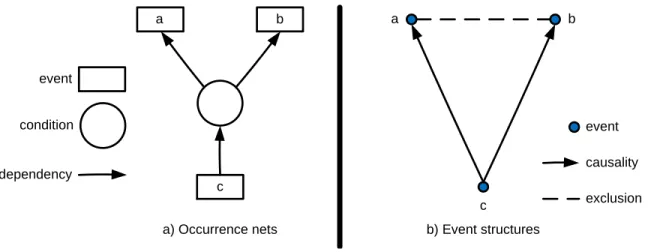
For various reasons, some events may exclude some others. It may be because physically two values cannot be at the same time at some place or because they compete for the same resource. Forwards conflicts in occurrence nets (see Fig. 1.1-a) are simple examples that induce an exclusion. a and b shares the same condition, so if a occurs then b will never occur and vice-versa. In, Figure 1.1-b, the relation is directly denoted by the dashed line connecting two events. The upper right figure denotes events as in place/transition nets. The lower right figure is more concise.
a) Forwards conflict in occurrence nets
a b
b) Exclusion in event structures
a b
event
dependency condition
b a
event
exclusion
Figure 1.1: Exclusion in occurrence nets and event structures
Some events may cause others. Causality is not really the right English word, it rather denotes a necessity [Win08]. In that context, a causes b does not mean that if a occurs then b must occur, but rather that b cannot occur, unless a has already occurred. In the following, we abusively use the terminology causality or causal dependency to remain consistent with other works on the topic. Figure 1.2-a illustrates the causal dependency on an occurrence net: events a and b cannot occur unless chas already occurred. Figure 1.2-b abstracts away the shared condition and directly represents the causal dependency with a plain arrow directed from thecause to theeffect. It must be acknowledged that this kind of causality is purely logical and not temporal (as might wrongly suggest the present perfect). It does not say anything about the date at which the events occur but only specifies the logical ordering in
1.2. EVENTS, CAUSALITY, EXCLUSION 7
which events must occur. It differs from the (temporal) precedence relation introduced later.
a b
a) Occurrence nets b) Event structures
a b
c
c event
dependency
condition event
causality exclusion
Figure 1.2: Causality and exclusion
There have been many presentations and variants of event structures. In [NPW79], elementary event structures are simply a partially ordered set (E,≤), where E is a set of events (occurrences) and ≤ ⊂ E × E is a partial ordering over E, called the causality relation. Assuming that in physical systems, there is an upper bound on the speed at which causality travels, a property of finite causes is considered:
∀e∈E,{e0 ∈E|e0 ≤e} is finite. Inevent structures, aconflict relation # ⊂E×E, a symmetrical and irreflexive relation on E, is added. The axiom of conflict heredity is stated as follows: ∀e, e0, e00∈E,(e#e0∧e0 ≤e00)⇒e#e00.
Later [Win86], the binary relations are replaced by N-ary relations. The en- abling relation generalizes the causality relation and stands for events that have multiple causes (AND-Causality [Gun92]) (see Fig. 1.3-a). A consistency predicate, Con ⊂ F in(E) over the finite subsets of E, generalizes the binary conflict relation by picking out some events that can occur together. Figure 1.3-b shows the domain of configurations for a simple consistency predicate. a is not directly in conflict with neither b nor c, since {a, b} ∈ Con ∧ {a, c} ∈ Con but a will never occur when both b and c have occurred. Ultimately, a, b, c cannot all occur: {a, b, c} ∈/ Con.
The binary exclusion implies the following simple rule on the consistency predicate:
(a#b)⇒(∀X ∈Con)({a, b}*X).
a b c
d
a) Enabling: {a,b,c} d b) Consistency:
Con = {{},{a},{b},{c},{a,b},{a,c},{b,c}}
{}
{a} {b} {c}
{a,b} {a,c} {b,c}
Figure 1.3: Enabling and consistency.
Flow event structures [BC88] are a more flexible notion of event structures ob- tained by relaxing the axiom of conflict heredity, the finite cause property and by replacing the causal dependency by a weaker (irreflexive) relation, the flow relation, denoted ≺.
1.3 Tag structures
The notion ofTag Systems has been initially introduced in the Lee and Sangiovanni- Vincentelli’s (LSV) tagged-signal model [LS98]. LSV is a denotational approach where a system is modeled as a set of behaviors. Behaviors are sets of events. Each event is characterized by a data value and a tag. It departs from the work on event structures by not relying on the category theory to be more accessible. The paral- lel composition of systems consists in taking the intersection of their corresponding sets of behaviors. Tag Systems gave rise to Tag Structures [BCC+08] and to Tag Machines [BCCSV05]. Tag structures aim at providing a compositional theory of heterogeneous reactive systems. They restrain the generality of tag systems and give more structure to the behaviors, which become finite sets of signals, signals being sequences of events. They also introduce the concept of stretching to allow certain deformations of the tags for behaviors. The stretching mechanism allows an entire
1.3. TAG STRUCTURES 9
characterization of the MoCCs. Parallel composition is allowed through the fibered product of tag structures and requires an appropriate algebra. More formally, a tag structure is a triple hT,≤,Φi, where:
T is a set of tags and (T,≤) is a partial order;
Φ is a set of increasing total functionsφ :T → T, the set of stretching functions.
This work departs from the event structures by considering timed systems. Tags are time stamps. For instance, the tag structure hN,≤,{id}i, where ≤ is the usual total order on natural numbers, can be used in modeling synchrony. Tags indicate the reaction indices. The tag structure hR+,≤,{id}i can be used in modeling time- triggered systems. Tags become real-time dates.
The stretching function Φ allows deformations of the tags. When Φ = {id} no deformations are allowed and the structure is rigid. When, for instance, Φ is the set of all dilating increasing functions, i.e.,functions φ such thatφ(τ)≥τ for allτ ∈ T, then the tags represent the earliest possible dates for execution of events.
Tag structures then consider a set of variables V. A behaviorσ considers a finite subset V ⊂ V with domain D and is a mapping defined as follows:
σ∈V →N→(T ×D)
meaning that, for each v ∈ V, the nth occurrence of v in behavior σ has tag τ ∈ T and value x ∈ D. For a given variable and a given behavior the clock is extracted.
The clock of v inσ is the first projection of the mapσ(v) and must be an increasing (order-preserving) function f :N→ T, i.e., f(≤N)⊆ ≤T.
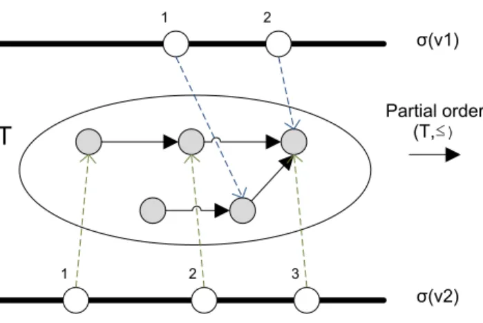
Figure 1.4 shows an example, where values are not displayed. T is a set of tags and the solid arrows denote the partial order ≤. Each bold line represents a behavior for a given variable. The dashed lines are the clocks for this behavior, the blue (upper) ones for variable v1 and the red (lower) ones for variable v2. Note that, the third event of v2 in σ has the same tag than the second event of v1 inσ. The two events occur at the same time, they are coincident.
1 2 3
T Partial order
(T,≤)
σ(v2)
1 2
σ(v1)
Figure 1.4: Tag structure by example
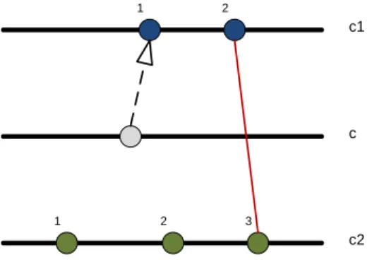
We consider that clocks are central in such a model as they are in synchronous languages. We propose a time model that abstracts away the values and focuses on the clocks themselves. Figure 1.5 shows the same example with logical clocks. The clockc1 represents the clock ofσ(v1), whereasc2 represents the clock ofσ(v2). Clock cis introduced to capture the lonely tag not used in any of these two behaviors. The plain vertical connection (in red) denotes a coincidence. The two instants (circles) represent occurrences of events that area priori independent. Forcing a simultaneous occurrence of the events is done by mapping them to the same tag in the tag structure model and by adding a coincidence relation in our model. The dashed arrow denotes the precedence relationship that gives the ordering between the occurrences of the two events. In this model, our clock is more an element of 2T with a proper total order relation rather than a mapping to T (TN) as in tag structures.
1 2 3
c2
1 2
c1
c
Figure 1.5: Logical clocks by example
1.4. LOGICAL TIME AND LOGICAL CLOCKS 11
The next section discusses further the notions of logical time and clocks indepen- dently of any specific model.
1.4 Logical time and logical clocks
Tag structures go beyond event structures by considering tags, which provide a sup- port to model timed systems. The wordtime is used here in a very broad sense where the relative ordering between events primes over the actual date. This logical time is widely used in models dedicated to embedded, real-time, reactive systems and in par- ticular it is the time model in use in synchronous languages [BCE+03]. Discrete-time logical clocks (or simply logical clocks) represent/measure the logical time. Clocks that refer to the “physical time” or real-time are called chronometric clocks. Logical clocks as originally defined by Lamport [Lam78] are a special case introduced as a support to build a distributed synchronization algorithm.
Logical time is sometimes qualified as multiform. Indeed, when renouncing to represent the physical time only, the same model can be used to represent chronolog- ical relationships between events on different natures. Chronology being the order in which a series of events occur. The events can be ticks of a processor or cycles of a communication bus, but also ticks emit by sensor that measures the rotation degree of a crankshaft in an engine or the sending of a message between two components.
(Logical) clocks are central in synchronous languages and play an important role in tag structures. We propose a model called the Clock Constraint Specification Language (ccsl) dedicated to building logical clocks and expressing relations on clocks. ccsl is described in the following chapter.
Chapter 2
The Clock Constraint Specification Language
The Clock Constraint Specification Language (ccsl) has initially been introduced as a companion language for theumlprofile for marte(Modeling and Analysis of Real- Time and Embedded systems). It has then become a domain-specific language (DSL) on its own and it is now developed independently. It aims at being a specification language to equip syntactic models (uml-based or other DSLs) with a timed causality model that explicitly expresses the causal and chronological relationships amongst events of the modeled systems.
The initial intent of martebeing to cover both design and analysis, a large set of ccslconstraints have been introduced for convenience on top of a relatively small set of kernel primitives. Section 2.1 introduces theccsltime model. Section 2.2 discusses some fundamental coincidence and precedence constraints. Then, Section 2.3 presents the integration of this model into uml, through marte stereotypes.
2.1 Instants, clocks and time structures
ccslfocuses on the events and their occurrences and abstracts away the values. This is a major difference with other related models (Signal, Tag structures), which usually
13
consider an event as a pair value/time stamp. In ccsl, the value may be added as an annotation and never influences the scheduling in any way. ccsl deals with sets of event occurrences I, called instants to avoid the possible confusion between the events and their occurrences. On these events we build a time structure hI,≺,≡iby considering the two primitive binary relations: strict precedence (denoted ≺) and the coincidence (denoted ≡). ≺ is irreflexive and transitive, it is only a partial relation and therefore is not asymmetric, there can be instants that are not related to each other. The coincidence is a direct emanation of synchronous languages. ≡is a partial equivalence relation, i.e., reflexive, transitive and symmetric. The coincidence is the major difference with the general net theory and the event structures because it forces one instant to occur when another has occurred or prevents an event from occurring when another one is not ready. The coincidence is universal, no referential can tell apart two coincident instants. Petri’s model (following the relativity theory) restricts coincidence to single points in space-time. In ccsl, the coincidence relationship
“melts”a priori independent points (instants) to reflect design choices and thus is a foundational relation.
From these two relations, we build three more: exclusion (denoted#),precedence (denoted 4) and independence (denoted k). The exclusion is when the instants can never be coincident. Note, that this definition of exclusion is weaker than the exclusion of event structures (see section 1.2), since it does permanently prevent the other event from occurring but just prevents them from being coincident. The precedence is the union of the strict precedence and the coincidence. It is the equivalent of the causality relation in event structures and 4 is a partial pre-order, i.e., it is reflexive and transitive but neither antisymmetric, nor asymmetric. If a 4 b and b 4 a then a is not necessarily identical to b but is coincident with it (a ≡ b). The graphical representation of instant relations is given in Figure 2.1.
All these relations are defined on instants (event occurrences). However, in a specification, it is more likely to talk about the events themselves and therefore we define aclock cas a totally ordered set of instantsIc. hIc,4ciis a total order1. 4cis
1Colors distinguish the total order on clocks in blue from the partial order on the time structure in red
2.1. INSTANTS, CLOCKS AND TIME STRUCTURES 15
i
j
i ≡ j
i j
i Y j
i j
i ≺ j
i j
#
i j
i j
||
i j
Figure 2.1: Graphical representation of instant relations
antisymmetric since no two instants of a given clock can be coincident without being identical. We chose the word clock, instead of events or signals to avoid confusion with these highly overridden words. The word comes from the synchronous languages, in which the clock is a pure signal (without values). It represents events, but the word event is sometimes used to denote the occurrences and sometimes to denote the classes of occurrences. Additionally, event also exists in uml and we therefore needed another word. Note that the set of instants can be either dense or discrete. A discrete-time clock is a clockcwith a discrete set of instants Ic. SinceIc is discrete, it can be indexed by natural numbers in a fashion that respects the ordering on Ic: letN? =N\ {0}, idx :Ic→N?,∀i∈ Ic, idx(i) = kif and only if iis thekth instant in Ic. c[k] is defined so as∀k∈N?,idx(c[k]) =k. °iis the unique immediate predecessor ofiinIc. For simplicity, we assume a virtual instant (called birth) the index of which is 0, and which is considered as the immediate predecessor of the first instant.
From a set of clocks C, we build a time structure hI,≺,≡isuch that
I =S
c∈CIc
≺=S
c∈C ≺c, where ≺c is the reflexive reduction of4c for a clock c
≡=IdI
Instant relations are then extended to clock relations, which usually represent infinitely many instant relations at once. The following section explains how, given a set of clocks and its underlying time structure, we augment it by considering a given specification, a set of clock relations Rel.
2.2 Clock constraints
Specifying a full time structure using only instant relations is not realistic, all the more so since a clock usually has an infinite number of instants therefore forbidding an enumerative specification of instant constraints. Instead of defining individual instant pairings, a clock constraint specifies generic associations between (infinitely) many instants of the constrained clocks.
In this section we define the most general clock constraints and we introduce some usual constraints, derived from the basic ones. The clock constraints are classi- fied in three main categories: 1) coincidence-based constraints, 2) precedence-based constraints, and 3) mixed constraints.
Actually, most constraints only partially constrain the systems and therefore sev- eral time structures are possible. So a specification induces a set of time structures that share the same set of instants I. For one given time structure T S, IT S = I denotes its set of instants, ≺T S is its precedence relation and ≡T S its coincidence relation.
2.2.1 Coincidence-based clock constraints
Coincidence-based clock constraints are classical in synchronous languages and can then be very easily specified with such languages.
Sub-Clocking is the most basic coincidence-based clock constraint relationship.
Let a, b be two clocks. The clock relation b isSubClockOf a imposes b to be a sub- clock of a. Intuitively, this means that each instant in b is coincident with exactly one instant in a (Figure 2.2). More formally, a time structure T S =hI,≺T S,≡T Si satisfies the clock relation b isSubClockOf a if and only if there exists an injective
2.2. CLOCK CONSTRAINTS 17
mapping h:Ib → Ia such that :
(1) h is order preserving:
(∀i, j ∈ Ib) (i 4b j) =⇒ (h(i) 4a h(j)) (2) an instant ofIb and its image are coincident:
(∀i∈ Ib)i ≡T S h(i)
A B h
Figure 2.2: Coincidence-based clock constraint
In what follows, this constraint is denoted as b ⊂ a, read “b is a sub-clock of a”
or equivalently “a is a super-clock of b”.
2.2.2 Derived coincidence-based clock constraints
h can be specified in many different ways.
Equality a = bis the symmetric relation that makes the two clocksa and b“syn- chronous”: his a bijection and the instants of the two clocks are pair-wise coincident.
It is strictly equivalent to b = a.
Other coincidence-based clock expressions allow the creation of a new clock, sub- clock of a given clock (denotednew clock ,def ining expression). Three such clock expressions are presented hereafter.
Restriction b ,a restrictedTo P where a is a given clock, b is a new clock, and P is a predicate on Ia× Ib, such that
(∀i∈ IA,∀j ∈ IB) i≡h(j)⇐⇒P(i, j) =true
Filtering b , a filteredBy w, where a and b are discrete-time clocks, and w is a binary word. For filtering, the associated predicate is such that
(∀i∈ Ia,∀j ∈ Ib) P(i, j) = true⇐⇒idxa(i) =w↑idxb(j)
where w ↑ k is the index of the kth 1 in w. The use of infinite k-periodic binary words in this kind of context has previously been studied in N-Synchronous Kahn networks [CDE+06]. This constraint is frequently used in clock constraint specifica- tions and is denoted A H w in this document. It allows the selection of a subset of instants, on which other constraints can then be enforced.
In what follows, a (periodic) binary word is denoted asw=u(v)ω, whereuis called the transient part ofw and v itsperiodic part. The powerω means that the periodic part is repeated an unbounded number of times. So,u(v)ω denotes u.v.v.· · ·.v.· · ·.
Periodicity Defining the periodicity of discrete clocks consists in using a binary word with a single 1 in the periodic part. b isPeriodicOna periodp offset d defines a periodic clock b. The same clock can be built with a filtering b , a H 0d.(1.0p−1)ω. In this expression, for any bit x,x0 stands for the empty binary word. Note that this is a very general definition of periodicity that does not require a to be chronometric contrary to the usual definition.
2.2.3 Precedence-based clock constraints
Precedence-based clock constraints are easy to specify with concurrent models like Petri nets but are not usual in synchronous languages. A discussion on main differ- ences with Time Petri nets can be found in some of our previous work [MA09].
2.2. CLOCK CONSTRAINTS 19
Precedence The clock constraint Precedence consists in applying infinitely many precedence instant relations. Two forms can be distinguished: the strict precedence a strictly precedes b, and the non strict precedence a precedes b. Intuitively, this means that each instant inbfollows one instant in a(Fig. 2.3). More formally, a time structure T S =hI,≺T S,≡T Si satisfies the clock relation a precedes b if and only if there exists an injective mapping h:Ib → Ia such that :
(1) h is order preserving:
(∀i, j ∈ Ib) (i 4b j) =⇒ (h(i) 4a h(j)) (2) an instant of Ib and its image are ordered:
(∀i∈ Ib) h(i) 4T S i
for the non strict precedence (∀i∈ Ib) h(i) ≺T S i
for the strict precedence
A B h
Figure 2.3: Precedence-based clock constraint
2.2.4 Derived precedence-based clock constraints
When a and b are discrete clocks, the precedence relationship gives rise to more specific constraints. Three often used precedence constraints are discussed here.
Discrete precedence A time structure TS satisfies a strictly precedes b (denoted a ≺ b) iff
(∀i∈ Ib)(k = idxb(i)) =⇒ a[k] ≺T S b[k]
There also exists a weak form (denoted a 4 b) of this constraint where ≺ T S is replaced by 4T S.
Alternation A time structure TS satisfies a alternatesWithb (denoted a ∼ b) iff:
a ≺ b
∧ b ≺ a0
,where a0 ,aH0.1ω
The equivalent following specification uses instant relations instead of clock relations, (∀i∈ Ia)(k= idxa(i)) =⇒ (a[k] ≺T S b[k]∧b[k] ≺ a[k+ 1]).
Synchronization A time structure TS satisfiesasynchronizesWithb(denoteda ./
b) iff
a ≺ b0
∧
b ≺ a0
where a0 ,a H0.1ω,and b0 ,bH0.1ω This constraint can also be expressed using instant relations:
(∀k∈N?)(a[k] 4T S b[k+ 1])∧b[k] 4T S A[k+ 1]).
Precedences used in the definition ofAlternation andSynchronization can be non- strict precedences, thus there exist four different variants of these clock relations. An- other extension considers instants by “packets”. For instance,abyαstrictly precedesbbyβ (denoted a/α ≺ b/β) is a short notation for
af ≺ bs
where af ,a H 0α−1.1ω
,and bs ,bH 1.0β−1ω
2.2.5 Mixed constraints
Mixed constraints combine coincidences and precedences. They are used to synchro- nize clock domains in globally asynchronous and locally synchronous models.
2.2. CLOCK CONSTRAINTS 21
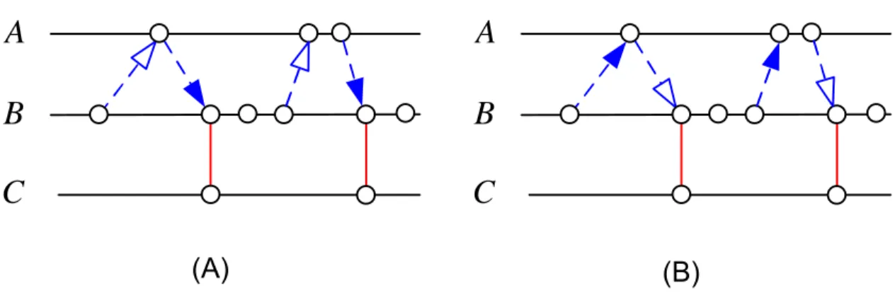
Sampling The commonest constraint of this kind is the Sampling constraint. c, asampledOnb, wherebandcare discrete clocks andacan be either discrete or dense, constrains the clocks a, b and c so that c is a sub-clock of b that ticks only after a tick of a (Fig. 2.4). A time structure TS satisfies c,a sampledOnb iff
(∀ic∈ Ic)(∃ib ∈ Ib)(∃ia ∈ Ia)(ic ≡T S ib)∧(ia 4T S ib)∧(°ib ≺T S ia)
B C A
B C A
(A) (B)
Figure 2.4: Sampling constraints
A time structure TS satisfies the strict form c,a strictly sampledOn b iff:
(∀ic∈ Ic)(∃ib ∈ Ib)(∃ia ∈ Ia)(ic ≡T S ib)∧(ia ≺T S ib)∧(°ib 4T S ia)
Delay A slight variation of the sampling is theDelayconstraint. c,adelayedForN b (also denotedc,a $b N) samples the clockaon the Nth occurrence of the discrete clock b. c is necessary discrete and is a subclock of b. a can be either discrete or dense.
Note that this operator is polychronous, contrary to usual synchronous delay operators (pre in Lustre, $ in Signal). There is also a binary variant of this ternary operator denoted $and which is equivalent to a delay when a is synchronous with b.
c,a $ N is equivalent toc,a $a N.
2.2.6 TimeSquare
Most constraints only partially constrain the system, which means that several (pos- sibly infinitely many) time structures may satisfy a set of constraints. timesquare has been built to implement ccsland provide support for the analysis of ccslspec- ifications. Several kinds of analyses are possible. Given a set of clocks and a set of constraints, the clock calculus engine can find one possible time structure that satis- fies all the constraints. Actually, this is done in simulation and the time structure is only built partially up to the current simulation point. Since it is not always possible to choose a single time structure in a deterministic way the simulation may be non de- terminate. The clock calculus relies on ccslstructural operational semantics (SOS) to run the simulation. A description of the SOS semantics is available in [And09].
The ccsl constraints are encoded as a set of Boolean equations that determines at each step, which clock can is enabled and which one is not. With non determinis- tic specifications several solutions (each of which may involve several clocks) may be valid. A simulation policy is then used to pick one solution and fire the associated clocks. Depending on which clocks were fired, the rewriting rules allows to process a new set of boolean equations. This ends the current simulation step and the sim- ulation engine proceeds to the next one. Several simulation policies are offered. For instances, the random policy randomly chooses one possible solution amongst the set of solutions. The minimum policy chooses a consistent solution where the number of firing clocks is minimal. The maximum policy chooses a consistent solution where the number of firing clocks is maximal.
Another kind of analyses is also possible. Given a time structure (e.g., defined as a by-product of the execution of some code) and a ccslspecification, one can verify whether the time structure satisfies all the constraints in the specification. This aspect is described further in the third part of this document. The time structure is given by an existing implementation of the system on which we have no control. The implementation forces some clocks to tick while preventing others to be fired. Our observer-based verification technique can be used to check that the implementation satisfies all the constraints of the specification.
timesquare has been implemented as a set of Eclipse plugins and is available for
2.3. UML FOR REAL-TIME AND EMBEDDED SYSTEMS 23
download athttp://www.inria.fr/sophia/teams/aoste/dev/time_square. time- square is protected by the APP (Agence pour la protection des programmes).
2.3 UML for Real-Time and Embedded systems
2.3.1 UML, SPT, Marte
The Unified Modeling Language (uml) [OMG09b] is a general-purpose modeling lan- guage specified by the Object Management Group (omg). It proposes graphical notations to represent all aspects of a system from the early requirements to the de- ployment of software components, including design and analysis phases, structural and behavioral aspects. As a general-purpose language, it does not focus on a spe- cific domain and maintains a weak, informal semantics to widen its application field.
However, when targeting a specific application domain and especially when building trustworthy software components or for critical systems where life may be at stake, it is absolutely required to extend the umland attach a formal semantics to its model elements. The simplest and most efficient extension mechanism provided by theuml is through the definition of profiles. A uml profile adapts the uml to a specific domain by adding new concepts, modifying existing ones and defining a new visual representation for others. Each modification is done through the definition of anno- tations (called stereotypes) that introduce domain-specific terminology and provide additional semantics. However, the semantics of stereotypes must be compatible with the original semantics (if any) of the modified or extended concept.
The umlprofile for Modeling and Analysis of Real-Time and Embedded systems (marte[OMG09a]) extends theumlwith concepts related to the domain of real-time and embedded systems. It supersedes theumlprofile for Schedulability, Performance and Time (spt [OMG05]) that was extending the uml 1.x and that had limited capabilities. martehas three parts: Foundations,Design and Analysis.
The foundation part is itself divided into five chapters: CoreElements,NFP,Time, Generic Resource Modeling andAllocation. CoreElements defines configurations and modes, which are key parameters for analysis. In real-time systems, preserving the
non-functional (or extra-functional) properties (power consumption, area, financial cost, time budget. . . ) is often as important as preserving the functional ones. The umlproposes no mechanism at all to deal with non-functional properties and relies on mere String for that purpose. NFP (Non Functional Properties) offers mechanisms to describe the quantitative as well as the qualitative aspects of properties and to attach a unit and a dimension to quantities. It defines a set of predefined quantities, units and dimensions and supports customization. NFP comes with a companion language called VSL (Value Specification Language) that defines the concrete syntax to be used in expressions of non-functional properties. VSL also recommends syntax for user-defined properties. Time is often considered as an extra-functional property that comes as a mere annotation after the design. These annotations are fed into analysis tools that check the conformity without any actual impact on the functional model: e.g., whether a deadline is met, whether the end-to-end latency is within the expected range. Sometimes though, time can also be of a functional nature and has a direct impact on what is done and not only when it is done. All these aspects are addressed in the time chapter of marte [AMdS07]. The next section elaborates on the time profile.
The design part has four chapters: High Level application modeling, Generic com- ponent modeling, Software Resource Modeling, and Hardware Resource Modeling.
The first chapter describes real-time units and active objects. Active objects depart from passive ones by their ability to send spontaneous messages or signals, and react to event occurrences. Passive objects can only answer to the messages they receive.
The three other parts provide a support to describe resources used and in particular the execution platform on which the application may run. A generic description of resources is provided, including stereotypes to describe communication media, stor- ages and computing resources. Then this generic model is refined to describe software and hardware resources along with their non-functional properties.
The analysis part also has a chapter that defines generic elements to perform model-driven analysis on real-time and embedded systems. This generic chapter is specialized to address schedulability analysis and performance analysis. The chapter on schedulability analysis is not specific to a given technique and addresses various
2.3. UML FOR REAL-TIME AND EMBEDDED SYSTEMS 25
formalisms like the classic and generalized Rate Monotonic Analysis (RMA), holistic techniques, or extended timed automata. This chapter provides all the keywords usually required for such analyses. In Chapter 5 of this document, we follow a rather different approach and instead of focusing on syntactic elements usually required to perform schedulability analysis (periodicity, task, scheduler, deadline, latency), we show how we can use marte time model and its companion language ccslto build libraries of constraints that reflect the exact same concepts. Finally, the chapter on performance analysis, even if somewhat independent of a specific analysis technique, emphasizes on concepts supported by the queueing theory and its extensions.
marteextends theumlfor real-time and embedded systems but should be refined by more specific profiles to address specific domains (avionics, automotive, silicon) or specific analysis techniques (simulation, schedulability, static analysis). The three examples addressed here consider different domains and/or different analysis tech- niques to motivate the demand for a fairly general time model that has justified the creation of martetime subprofile.
2.3.2 Marte Time profile
Time in sptis a metric time with implicit reference to physical time. As a successor of spt,martesupports this model of time. uml 2, issued afterspt, has introduced a model of time called SimpleTime [OMG09b, Chap. 13]. This model also makes implicit reference to physical time, but is too simple for use in real-time applications and was, right from the beginning, expected to be extended in dedicated profiles.
martegoes beyondsptanduml2. It adopts a more general time model suitable for system design. In marte, Time can be physical, and considered as dense, but it can also be logical, and related to user-defined clocks. Time may even be mul- tiform, allowing different times to progress in a non-uniform fashion, and possibly independently to any (direct) reference to physical time.
In marte, time is represented by a collection of Clocks. Each clock specifies a totally ordered set of instants (see Section 2.1). There may be dependence relation- ships between instants of different clocks. In practice, clocks should be associated
with events whose occurrence should be constrained or with events used to constrain others. In uml, TimeEvent is specialization of Event stating that this special kind of events can carry a time stamp. Our intent is to allow any kind of event to carry a time stamp. For instance, the goal would be to constrain the way a message is sent or received, a behavior starts or finishes its execution. Therefore time (or causality) must be orthogonal to the various events and not a special kind of events.
The marteTime profile defines two stereotypes ClockTypeand Clock to represent the concept of clock. ClockTypegathers common features shared by a family of clocks.
TheClockTypefixes thenatureof time (dense or discrete), says whether the represented time is linked to physical time or not (respectively identified as chronometric clocks and logical clocks), chooses the type of the time units. A Clock, whose type must be a ClockType, carries more specific information such as its actual unit, and values of quantitative (resolution, offset, etc.) or qualitative (time standard) properties, if relevant.
TimedElement is another stereotype introduced in marte. A timed element is explicitly bound to at least one clock, and thus closely related to the time model.
For instance, a TimedEvent, which is a specialization of TimedElement extending uml Event, has a special semantics compared to usual events: it can occur only at instants of the associated clock. In a similar way, aTimedValueSpecification, which extendsuml ValueSpecification, is the specification of a set of time values with explicit references to a clock, and taking the clock’s unit as time unit. Thus, in a marte model of a system, the stereotype TimedElement or one of its specializations is applied to model elements which have an influence on the specification of the temporal behavior of this system.
ThemarteTime subprofile also provides a model library namedTimeLibrary. This model library defines the enumerationTimeUnitKindwhich is the standard type of time units for chronometric clocks. This enumeration contains units like s (second), its submultiples, and other related units (minute, hour. . . ). The library also predefines a clock type (IdealClock) and a clock (idealClk) whose type is IdealClock. idealClk is a dense chronometric clock with the second as time unit. This clock is assumed to be an ideal clock, perfectly reflecting the evolutions of physical time. idealClk should be
2.3. UML FOR REAL-TIME AND EMBEDDED SYSTEMS 27
imported in user’s models with references to physical time concepts (i.e., frequency, physical duration, etc.).
2.3.3 UML and formal methods
Theumlis a general-purpose modeling language. Its semantics is described in English in the omg specification. Several aspects are left unspecified in so-called semantic variation points to allow user-defined adaptations for addressing domain-specific is- sues. There have been many efforts to use theumlin formal environments to address critical systems or domains where formal verification is mandatory. A brief classifi- cation is attempted hereafter even though it is usually acknowledged [BLMF00] that building a full taxonomy is difficult:
1. The first kind consists in using a formal language to build uml expressions and/or constraints. Since, uml does not enforce any specific syntax for ex- pressions and constraints, any language can be used. Even though the Object Constraint Language (OCL) [OMG06] may seem the most natural choice, for- mal languages (e.g., Z [GL00], Labelled Transition Systems [SCK09]) are also used to specify invariants in uml use cases or pre-condidions/post-assertions on uml operations. Then, scenarios (uml interaction diagrams) or behaviors (state machines or activities) are statically analyzed [CPC+04, GBR07, YFR08]
to check whether the use case invariants and the post-assertions hold.
2. The second kind of approaches is transformational. It consists in transforming every uml model element into a model element of a formal language (for in- stances, Petri Nets [St¨o05] orπ-calculus [YsZ03]). After transformation, various analyses become possible, like symbolic model-checking [Esh06].
3. In the third kind, the semantics resides in annotations (stereotypes). For in- stance, the semantics of Concurrent Sequential Processes [Hoa78] can be given to a uml state machine provided that a umlprofile for Concurrent Sequential Processes [FGL+08] is defined.
4. In the fourth kind, only a subset of the uml is allowed to make it suitable for a specific domain, e.g., the uml state machines can be reduced to timed automata [AD94] thus giving access to a whole family of formal tools [BDL+06].
In all cases, the semantics remains outside the model and therefore the model may be interpreted differently by another tool or another user. The purpose of ccsl is to provide a domain-specific language (DSL) to build an explicit semantic model that would be linked into the model itself to define its time/causal semantics. Our approach is not specific toumlmodels and can be used with domain-specific models as well. We propose to use the martetime model and its companion languageccsl (Clock Constraint Specification Language) to build the semantic model.
2.3.4 UML and synchronous languages
Synchronous languages [Hal92, BCE+03] are well-suited to formal specification and analysis of reactive system behavior. They are even more relevant with safety-critical applications where lives may be at stake. However, to cover a complete design flow from system-level specification to implementation, synchronous languages need to interoperate with other, more general, specification languages. One of the candidates is the uml associated with sysml, the uml profile for systems engineering [Wei08, OMG08]. This is very tempting since synchronous languages internal formats rely on state machines or data flow diagrams both very close to uml state machines and activities. Moreover, SyncCharts [And96] are a synchronous, formally well-founded, extension ofumlstate machines and are mathematically equivalent to Esterel [Ber00], one of the three major synchronous languages. As for sysml, it adds two constructs most important for specification: requirements and constraint blocks (see 2.3.5).
There have been attempts to bridge the gap between the uml and synchronous languages. Some [LD06] choose to import uml diagrams into Scade, a synchronous environment that combines Safe State Machines (SSM—a restriction of SyncCha- rts) together with block diagrams, the semantics of which is based on Lustre. Oth- ers [BRG+01] prefer to define an operational semantics of uml constructs with a synchronous language, like Signal. In both cases, the semantics remains outside
2.3. UML FOR REAL-TIME AND EMBEDDED SYSTEMS 29
the uml and within proprietary tools. Other tools, from the same domain, would interpret the same models with a completely different semantics, not necessarily com- patible. Therefore, it is impossible to exchange diagrams between tools, not only because of syntactical matters but also for semantic reasons. Different environments are then competing rather than being complementary. To provide full interoper- ability between tools of the embedded domain, the uml absolutely requires a timed causality model. The uml Profile formartehas introduced a time model with that purpose (see 2.3.1). Its companion language,ccslis advertised as a pivot language to make explicit the interactions between different models of computations [MAdS08], like Ptolemy directors [EJL+03]. It offers a rich set of constructs to specify time requirements and constraints.
2.3.5 SysML/Marte
The umlprofile for System Engineering (sysml) [OMG08] is an adopted omg Spec- ification to be used at the system level. sysml is based on a selected subset of uml constructs, called UML4SysML, and provides few new extensions amongst which Re- finement and Parametric diagrams. The former helps making explicit system-level requirements and tracing their proposed implementations. The latter should be used to represent “non-causal” relationships amongst values of the system and possibly making explicit within the model, physical laws required for the design. “non-causal”
is used here to denote equations in which variables are not assigned a particular role or direction. In F = m×γ, no distinction is made between F, m and γ. A causal or functional interpretation would have considered m and γ as inputs and F as an output.
So, we can use this sysml construct to represent laws related to time, whether physical or logical. sysml recommends building a new “Constraint Block” for each new law and uses these blocks in so-called parametric diagrams to apply a law to relevant design values. Inccsl, there is a small number of identified relations among logical clocks. Consequently, we can easily construct a library of ccsl-specific con- straint blocks. Figure 2.5 shows accslspecification expressed usingsysmlconstraint
blocks and parametric diagrams.
par [ConstraintBlock] PeriodicAperiodicPeriodic
« clockType » {isLogical, nature=discrete}
Thread
Parameters super : Thread sub : Thread P : UnlimitedNatural
: UnlimitedNatural constraints {{CCSL} sub isPeriodicOnsuper
period=P offset= }
« constraint » Periodic
parameters super : Thread sub : Thread trigger : Thread
constraints { {CCSL} sub = trigger
sampledOn super }
« constraint » Sampling parameters a : Thread b : Thread
constraints { {CCSL} a alternatesWithb }
« constraint » Alternation bdd[package] CCSL
: Periodic sub:
t1_p : = 2 P:
offset : = 0 super:
c_100
: Periodic sub:
t2_p : = 4 P:
offset : = 0 super:
: Alternation a:
b:
t1 : Alternation
a:
b:
step1
t3 step3 : Sampling
sub:
super:
trigger:
step2
Figure 2.5: SysML parametric diagrams
The left-hand side part is an excerpt of the library. Three constraint blocks (Periodic, Alternation, Sampling) have been defined for each of the threeccsl relations introduced previously. Each constraint block has three compartments. The bottom one, calledparameters contains typed formal parameters. The middle compartment, called constraints, contains the constraint itself that applies on the parameters. In our case, the constraint is defined inccsl. However, this library is built once and for all, so end-users need not being entirely familiar with the concrete syntax and only need to be familiar with underlying concepts.
The right-hand side part models the followingccslspecification as asysmlpara- metric diagram:
t 1 isPeriodicOn c 1 0 0 period=2 o f f s e t=0 // p e r i o d i c t h r e a d t 1 t 3 isPeriodicOn c 1 0 0 period=4 o f f s e t=0 // p e r i o d i c t h r e a d t 3 t 1 alternatesWith s t e p 1 // t 1 e x e c u t e s s t e p 1
s t e p 1 alternatesWith s t e p 2 // s t e p 2 s t a r t s when s t e p 1 f i n i s h e s s t e p 3 = s t e p 2 sampledOn t 3 // s t e p 3 s a m p l e s t h e r e s u l t from s t e p 2
In such a diagram, boxes are properties extracted from the model. Some of the properties are clocks (t1, step1 . . . ), some others have integer values (of f set, t1 p . . . ). These properties may come from different diagrams and different blocks. The
2.4. THE FUTURE OF MARTE TIME MODEL 31
rounded rectangles are usages of constraint blocks. Their ports, which represent parameters, are connected with properties using non-causal connectors. Being non- causal means that there is no input or output, whichever value is known causes the other to update. For instance, considering Alternation, if b is known, one can deduce (partially) a but if a is known, then one can deduce (partially) b. This example is further presented in Chapter 5.
2.4 The future of MARTE Time Model
marte v1.0 has been adopted in November 2009 and the first revision committee should release marte v1.1 by the end of 2010. The major modification in revision v1.1 concerning the time model is to authorize the stereotype clock to extend the metaclass Event. The intent of this modification is to make it clear that any event of any kind (Call, Time, Send, . . . ) can be used as a logical time base in time specifications. They are no major modifications anticipated for release v1.2, but we shall continue our effort to disseminate marte and to increase the tool support. A second important requirements is to maintain and enhance the compatibility with sysml. The objective of next year being to provide sysmlwith a lighter time model that would be compatible with marte. sysml users do not seem ready to accept a textual language (like ccsl). Working with predefined domain-specific libraries as explained in Section 2.3.5 is one possible solution. An alternative would be to provide a better integration with the OMG’s Object Constraint Language (ocl), more and more used, by offering a logically timedocl. Timedoclextensions already exist [F02] but propose to extendoclwith temporal logics constructs which is rather different from our objective.
Chapter 3
How does CCSL compare ?
This chapter compares ccsl to other closely related concurrent models: Petri Nets, Process networks, Signal. The comparison to Petri Nets and to Signal has been pub- lished at ISORC’09 [MA09] and the work on using the hierarchization mechanism has been published in the workshop MOBE-RTS [YTB+10]. The comparison to process networks have been accepted to be published in September 2010 in the proceedings of FDL 2010.
33
3.1 Petri Nets
3.1.1 Time Petri nets
marteTime model conceptually differs from Petri’s work on concurrency theory [Pet87].
Petri’s theory restricts coincidence to single points in space-time. In our model, the foundational relationship coincidence gathersa priori independent points (instants) to reflect design choices.
Petri nets have well-established mathematical foundations and offer rich analysis capabilities. They support true concurrency and can be used to specify some of our clock relations. However it is not possible to force two separate transitions to fire
“at the same time”, i.e., to express coincidence. Thus, we use Time Petri net, the Merlin’s extension [Mer74] that associates a time interval (two times a and b, with 0 ≤ a ≤ b and b possibly unbounded) with each transition. Times a and b, for transition t, are relative to the moment θ at which the transition was last enabled. t must not fire before timeθ+aand must fire before or at timeθ+bunless it is disabled (in case of conflicts) by the firing of another transition. Even with this extension, the specification of ccsl constraints is far from straightforward.
In our representation, each marte discrete-time pure clock c=hIc,≺ci is repre- sented as a single transition ct (called clock transition) of a Time P