The purpose of this thesis is to investigate the performance of layered perovskites PrBaCo2O6-δ (PBC) and PrBaCo1.4Fe0.6O6-δ. PBCF) when implemented as cathode materials in a secondary laboratory aqueous zinc air cell. Half-cell tests were devoted to the verification of electrocatalytic activity of the perovskites in a three-electrode configuration via voltammetry techniques.
INTRODUCTION
Among them, perovskites have very recently attracted attention due to the tunability of their composition, leading to oriented intrinsic catalytic activity. First, a brief discussion is provided on the functions, limitations and possible developments of each component of the ZAB system, with an emphasis on the gas diffusion electrode.
ZINC-AIR BATTERY PRINCIPLES
Configuration
- Anode – Zinc Electrode
- Electrolyte and Separator
- Cathode – Air electrode
The electrolyte forms the intermediate link between the anode and the cathode and completes the cell's electrical circuit. To extend the hydrophobicity of GDL and prevent electrolyte infiltration, certain hydrophobic agents (also termed as binders or conducting polymers) such as PTFE Polyvinylidene fluoride (PVDF) [65, 66] and fluorinated ethylene propylene (FEP) [67, 68] have been investigated.
![Figure 1 : Cubic perovskite unit cell. Blue spheres represent the B cations, yellow spheres represent the A cations, and red spheres represent oxygen anions forming an octahedron [102]](https://thumb-eu.123doks.com/thumbv2/pdfplayerco/325782.50311/29.892.172.455.364.657/figure-perovskite-spheres-represent-cations-represent-represent-octahedron.webp)
PEROVSKITE-BASED CATALYSTS APPLIED IN ZABS
In the same direction, research was carried out to replace the A-site of perovskite-lanthanum cobaltite with calcium, while different morphologies of the corresponding perovskite were investigated [117, 118]. Maria Mechili 19 The modification of the B site of a perovskite is another strategy to experiment on the electronic and ionic conductivity of the perovskite and therefore certain experiments were carried out on the doping of the Co sites of perovskite PrBa0.5 Sr0.5 CoO5+δ. The performance of the fabricated ZAB is noteworthy, as it produced a high peak power density (128mWcm-2) and demonstrated the bifunctionality of the catalyst.
A lab-scale ZAB system incorporating the appropriate catalyst achieved 220 cycles at a current density of 10 mAcm-2, surpassing the durability of ZAB with pristine LaNiO3 [122]. The higher valence of Co (Co3+) and the larger surface area contributed to the higher ORR and OER efficiency of the doped. The catalyst maintained great stability with the long-term cycles of the domestic ZAB, which was cycled in deep charge and discharge (30 min charge & 30 min discharge).
One approach to the functionalization of perovskites, as previously mentioned [91], is to incorporate compounds with suitable characteristics on the perovskite surface. The durability of the fabricated ZAB for 100 (20 min) cycles at a current density of 10 mAcm-2 and the limited voltage gap across those cycles strongly imply improved catalyst bifunctionality. The advantages of the cooperation of perovskite and CNTs are profoundly demonstrated by the performance of the ZAB system they were integrated into.
EXPERIMENTAL METHODS AND PROCEDURE
Electrochemical characterization methods
- Electrochemical Half-Cell tests
- Electrochemical Full Cell- Tests
However, a comparison of the voltage responses of the two catalysts can be made. The first metric of battery cell performance is the open circuit voltage (OCV) of the cell. After determining the current-voltage profile of the cell, the actual battery capacity (Ah), specific capacity (Ah/kg), specific energy (Wh/kg), energy density (Wh L-1 or Wh cm-2) and operation (working) Voltage (V) cells should be determined.
DOD is the percentage of battery capacity that is discharged compared to the maximum capacity of the battery. It is therefore understandable that the value of the voltage depends on the state of charge (SOC%) of the battery. SOC expressed the remaining capacity of the cell as a percentage of the maximum capacity it can deliver.
Maria Mechili 34 These characteristic features of the battery are determined by a single galvanostatic discharge. After evaluating the cell's performance as a primary battery, the catalyst should be tested for bifunctionality. It is also desirable that the magnitude of the voltage gap remains stable throughout the cycle stability test.
Materials and Setups
Regardless of the parameters, important information can be obtained from the continuous cycle voltage profile (V-t) plots. Obviously, the number of hours and cycles of continuous circulation can give an overview of the stability of the catalyst. Most importantly, when evaluating the cycle graph, the voltage gap between the charge and discharge voltages provides information about the durability of the bifunctional catalyst.
The initial voltage difference of the first cycles preferably has a value lower than 1 V and, however limited it is, the polarization of the catalyst is lower, leading to better performance. Usually the catalyst can be used in a cycle until the voltage gap is long enough to claim that the catalyst is not performing sufficiently. The reference electrode was saturated Ag/AgCl and the counter electrode was a commercial platinum mesh. The electrolyte was an aqueous solution of 0.1 M KOH and 0.05 M sodium sulfate (Na2SO4), which promotes ionic conductivity in the circuit.
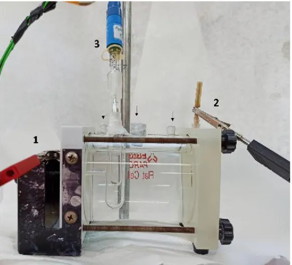
Two layers of a microporous membrane (Celgard 3401) were used on both sides of the electrolyte as separators. A nickel grid was the cathode current collector and a Cu grid the corresponding anode collector, while the highest ionic conductivity was achieved 6M KOH solution was used as electrolyte. Both the zinc-air cells and the assembly sequence of the components can be found in [Figure 10 and Figure 11].
RESULTS
Half-Cell Tests – ORR/OER Evaluation
Accordingly, the same ORR polarization was realized when PBC and PBCF catalyst were coated on the carbon cloth. Maria Mechili 42 Figure 14: ORR polarization of PBCF catalyst coated on CC; N2-saturated and O2-saturated As predicted, pure CC shows no activity in the 4-electron transfer region toward the ORR, in contrast to PBC and PBCF. This noticeable difference in the potential region of interest confirms the existence of an ORR with an initial overvoltage around 500 mV.
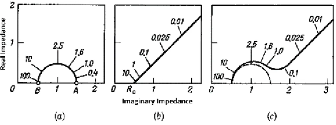
The anodic peak can be attributed to possible slight oxidation of the carbon surface of the carbon cloth. Maria Mechili 46 EIS spectra were obtained from 1 MHz - 1 Hz, although no semicircles were observed, as the data formed an ascending line representing the resistance caused by bulk diffusion. Maria Mechili 48 to achieve a current density of 4 mAcm-2 can be compared between catalysts as seen in Figure 18.
The two samples of PBC and the two samples of PBCF exhibit reproducible behavior in reductive and oxidizing polarizations, while the CV plots maintain the same shape throughout all cycles, indicating stable ORR/OER activity. Maria Mechili 52 Figure 23: (a) Reduction region for PBC and PBCF (b) Oxidation region for PBC and PBCF. Maria Mechili 53 From the above figures, it can be deduced that the ORR activity of the two catalysts appears almost identical, while PBCF shows slightly sharper activation towards OER.

Full-Cell tests – Battery Performance
Maria Mechili 54 Then, PEIS spectra were acquired to get a first idea of the connections and impedance sources in the cell system, before redox reactions occur, as seen in Figure 25. Sufficient connection between the battery cell components was verified. , since all OCV values approximate each other while the theoretical voltage of 1.65 V and the resistance of the electrolyte (RHF) have a negligible height. After explaining the conditions that affect the capacity performance of the cell, it is important to determine the appropriate discharge current before proceeding to determining capacity.
Furthermore, when a cell was fully discharged, it was decided to stop the discharge of the cell at a cut-off voltage of 0.8 V to prevent possible degradation of any component of the cell. Nevertheless, PBCF provided a greatly reduced specific capacity of 92 mAhg-1, which corresponds to only 10% of the theoretical specific capacity of a zinc electrode. The charging of the batteries is done first to define the voltage profile for charging and most importantly to have a representative data recorder when performing the continuous cycling afterwards.
Maria Mechili 61 The outstanding stability of the OER of PBCF compared to PBC is also verified by the charge profile of the two catalysts. The corresponding charge and discharge cycle curves of Zn–air rechargeable batteries are available in the figures below. Previous electrochemical and battery test results implying better catalytic activity of PBCF are confirmed by the prominent Voltage Profile of the catalyst when cycling.

DISCUSSION AND CONCLUSIONS
Furthermore, cathodes were prepared by manual drop casting with a pipette, so the distribution of catalyst ink in each experiment, besides the insert, cannot be completely comparable. Thus, no definite comparative conclusions can be drawn with reference to the differences in the performance of PBC and PBCF. The first implication of such an assumption is that the B site of the perovskite, consisting of a metal which can change valences, constitutes the "active site" of the perovskite, which is mainly responsible for its electronic conductivity.
All of the above considerations provide significant suggestions that Fe doping of cobalt sites in PBC is likely primarily responsible for the favorable performance of the catalyst when applied in the laboratory ZAB. After examining the performance of the two experimental cathodes in laboratory ZABs, it is useful to provide some comparable results from recently applied catalysts in ZABs. Second, it is observed that some of the catalysts mentioned in the Table and in the Introduction utilize the synergistic effects of heterostructures composed of different chemical species.
This can be attributed either to the inadequate practical composition of the ZAB configuration or to the insufficient content of a strongly hydrophobic binder in the preparation of the cathode electrode. When the electrolyte blocks the entry of oxygen molecules, the oxidant of the redox system cannot enter all the mass diffusion paths towards the TPB and the ORR activity is greatly reduced, leading to harmful overvoltages. Finally, the combination of PBCF particles decorating carbon highly porous structures could solve some of the problems arising from agglomerated PBCF particles.

PUBLICATIONS
Lee, J.-s., et al., High energy density metal-air batteries: Li-air versus Zn-air. Zhang, W., et al., Recent Advances in Isolated Monoatomic Catalysts for Zinc-Air Batteries: A Focus Review. Wang, X., et al., High performance platinum-perovskite composite bifunctional oxygen electrocatalyst for rechargeable Zn-air battery.
Zeng, S., et al., All-in-One Bifunctional Oxygen Electrode Films for Flexible Zn-Air Batteries. Xu, N., et al., Superior stability of a bifunctional oxygen electrode for primary, rechargeable and flexible Zn-air batteries. Bu, Y., et al., A highly efficient and robust cation ordered perovskite oxide as bifunctional catalyst for rechargeable zinc-air batteries.
Miao, H., et al., In situ deficiency/excess effects of LaMnO3 perovskite as a bifunctional oxygen catalyst for zinc-air batteries. Bian, J., et al., Mg Doped Lanio3 Perovskite Nanofibers as an Efficient Bifunctional Catalyst for Zinc-Air Rechargeable Batteries. Lee, J.-S., et al., High energy density metal-air batteries: Li–Air versus Zn–Air.