In addition, aging effects play an important role in both the panels and the inverter of the solar energy system. This thesis reviews the existing literature on time-dependent and variational effects. Modeling and analysis of the module and controller are performed to verify the improvement of the overall efficiency of the solar panel system.
A global controller for choosing the configuration in the system at runtime is proposed in order to improve the system efficiency.
Introduction
- Context and Motivation
- Objectives
- Structure of the Thesis
- Solar Cell
- SOLAR CELL 15
- SOLAR CELL 17
- Temperature Dependence
- Irradiation Dependence
- Transient Model
- MODULE 19
- Module
- MODULE 21
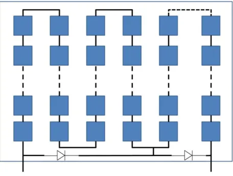
- MODULE 23 by the good cells forward biases causing the reverse bias of the poor cells in
- Control
- CONTROL 25
- CONTROL 27 run-time or on-time controllable parameters.The monitors are the power, the
- Limitations of the State of the Art
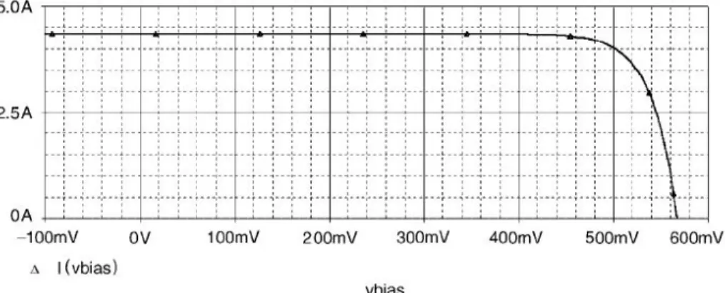
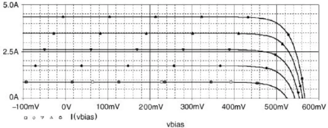
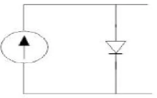
The most important elements of the system are the solar cells that convert the sun's energy into electricity. In the figure this is shown by the intersection of the I-V curve with the current axis. Voc, open-circuit voltage, which depends mainly on the saturation current of the diode.
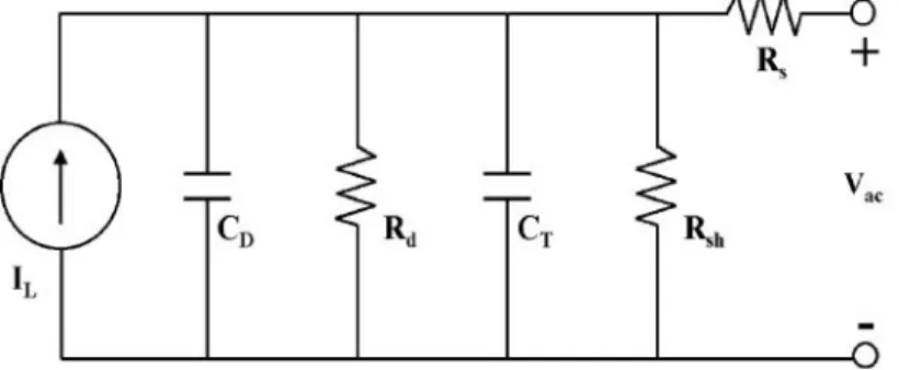
In the gure it is represented by the intersection of the I-V curve with the voltage axis. The addition of the non-ideal components is shown in gure[] and leads to the following feature [2]. The function of the solar cell is directly related to the sunlight and the radiation level.
The short-circuit current is a superposition of the photogenerated current and the dark current produced by the diode [1]. The above description of the solar cell corresponds to a steady-state behavior of the system. The power produced by a single solar cell depends on the cell's technology and its area.
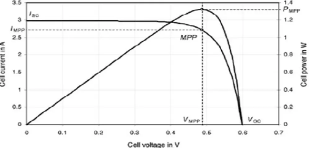
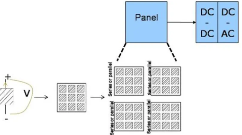
A combination of series and parallel connections of modules is used to increase current and voltage. The purpose of the control is to have maximum power generation from the system. Achieving maximum efficiency requires the cells to continuously operate at peak power.
Therefore, the prediction of the future evolution of the system is not yet really considered.
Solar Cell
Spice Modeling
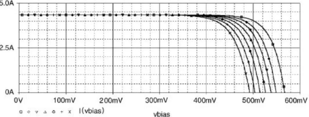
As previously mentioned, the amperage of the photogenerated current is proportional to the level of radiation falling on the cell. One voltage is the radiation intensity which can be changed by shading and the other is the maximum possible current produced, which depends on the location, weather conditions, the given angle of inclination and the orientation of the panel. Although the radiation incident on the cells is ultimately the product of the two voltages, the different time constants and available data led to such a separation.
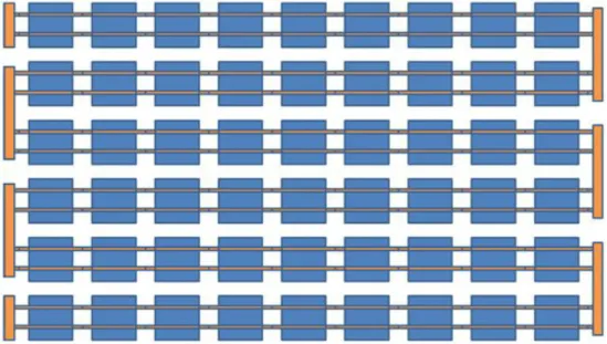
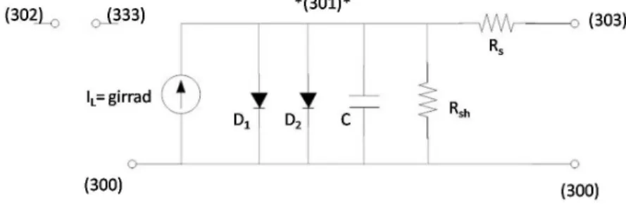
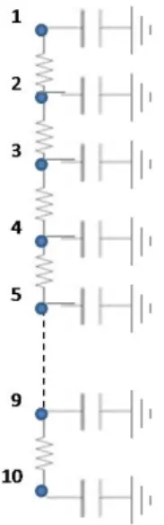
To simulate a solar module, the circuit of the solar cell is replicated several times, since the cell is the basic component of the photovoltaic system. The sequential use of the cell model leads to the implementation of the cell as a subcircuit, which enables reuse without reasoning internal nodes and elements of the cell circuit. To create an instantiation of a cell, four external nodes must be dened, as shown in the following figure.
Nodes number 302 and 333 are connected to the voltages representing the radiation input, while nodes 300 and 303 are the two terminals of the solar cell. The electrical components, diodes, resistors and capacitors, are described and placed within the subcircuit, but their value depends on the parame-.
SPICE MODELING 33
All parameters are calculated relative to the cell surface, while the temperature dependence in this model refers to the operation of the diodes, where the dependence is a built-in function in the spikes. The main questions of this research study at the cellular level are within the objectives stated in the introduction. Simulation of the module under dynamic conditions requires an equivalent electric cell model that includes transient behavior.
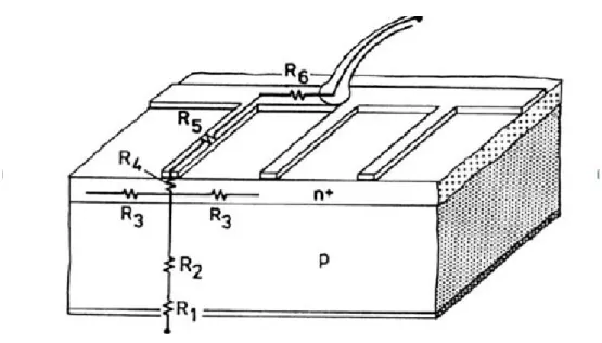
As can be seen from the model described above, the parameter values correspond to a cell of square centimeter of area, and according to the length and width of each cell, the actual parameters are calculated in spices. Apart from the front and rear contact metal, the cell layers are uniform, allowing the distribution of the cell model. The metallization used as a contact on the front of the cell cannot be uniform, as light must pass through in order for the semiconductor to absorb photons.
As mentioned in the previous chapter, the resistance of this metallization is included in the series resistance of the cell, which prohibits a separate analysis of the interaction of the metal contacts and wires of the module. The back contact of the cell is not uniform to have less metal in the module. Another reason for the division of the series resistance into its individual components is the independent influence of temperature on each of the components.
SPICE MODELING 35 the reason which this separation is needed is described here, the eort made
Solar Cell Parameters
SOLAR CELL PARAMETERS 37
The capacitance value was taken from the literature [11] and is C=35nF/cm2.
Irradiation Input
IRRADIATION INPUT 39 In order to reuse as much information as possible, the location chosen
As mentioned in the last chapter, the topology of the module used in industry is static. The static topology is designed based on worst-case operating conditions, and the controller, which uses an MPP tracking algorithm, takes into account uniform electrical characteristics at the level it is connected to. The main idea of the proposed module is to have a dynamic conguration of the system, therefore introducing node-controlled topology and local DC/DC converters.
The topology and button positions will be determined by the controller during operation using the concept of system scenarios. The controller in this case is global, so that each local DC converter that is connected optimizes the output of the chain of cells, but interacts with other converters through this controller. Each scenario corresponds to a set of different module configurations, leading to improved system performance under dynamic conditions.
Proposed Interconnect Model
Matlab Model
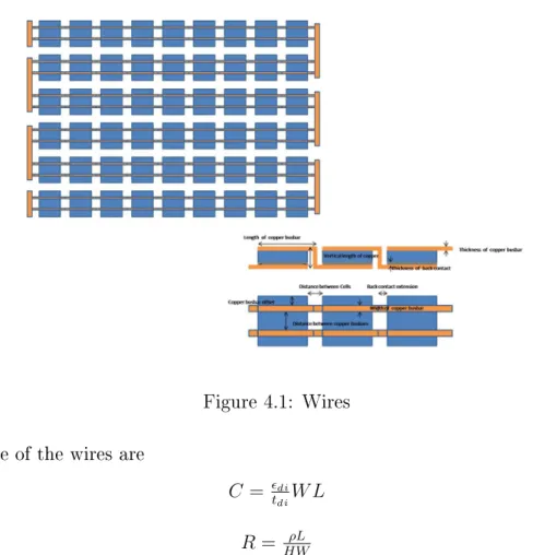
Instantiation of the Module
In the above equations, W and L are the width and length of the wire respectively, H is the thickness of the wire and tdi is the thickness of the dielectric layer. The parameters di and ρ are respectively the permittivity of the dielectric layer and the resistance of the metal wire [15].
Experimental Results
HFSS
HFSS 47
HFSS 49 are shown in gures 4.1,4.5 and 4.6
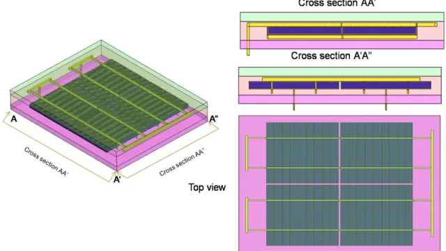
The dimensions of this module, and mainly the ratio of the dimensions in the xy plane to those in the z axis, are beyond the simulation capability of HFSS. To overcome this difficulty, the size of the module was reduced to 2x2 and some characteristic views are shown in figure 4.7. The model, in addition to the basic structure, is fully described by parameters that allow reuse in case of different dimensions of the elements. The entire cell body in this model is silicon and is not divided into an n- and p-type region, as the simulation is focused on the metal parts of the module and for this purpose uniformity is acceptable.
The frequencies in which the solar module operates are in the Hertz and Kilohertz range and HFSS is mainly used for high-frequency simulations. Low-frequency stimuli combined with the ratio of module sizes made the mesh definition extremely demanding in terms of memory usage. To enable the simulation, the model was further reduced to the size of a single cell.
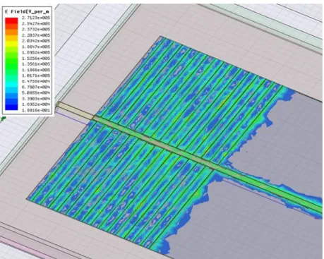
The final output of HFSS was a 2-port testbed le of a cell with a symmetry boundary. Some intermediate results of the electric field of the cell are shown in figure 4.8 and 4.9.
Thermal Model
THERMAL MODEL 53, where l the thickness of the layer, A the area of the layer, k the thermal.
THERMAL MODEL 53 ,where l the thickness of the layer, A the area of the layer, k the thermal
In Chapter 4, a switch-controlled module configuration is presented in order to exploit the dynamic nature of the system. This overhead consists of adding the controller hardware and the power consumed while it is active. These two cost components are compensated by integrating the controller into the module and reducing the active control frequency.
The proposed control method is based on the concept of system scenarios, which is analyzed in the second section of this chapter.
Conclusions
The methodology of this concept is explained and its illustration on a photovoltaic system is described. Comparing the performance of these configurations illustrates the optimization that can be achieved with a button-controlled configuration. Shown is the maximum power produced by the module's dynamic configuration, which can be 30% greater than the power produced by the state-of-the-art configuration.
In roof applications where during the design of the system it is not possible to avoid partial shading or the same orientation on each module, the time-varying effects become the most important factor. Further analysis of the impact of the metallization of the module is required and exploitation of the HFSS results. Coupling of the thermal and the electrical model is necessary for the transient behavior of the system.
Coupling the thermal and electrical model would allow for perturbations other than radiation, such as temperature and humidity. Future works include extending matlab le to include the connection of dc/dc converters. The switches used for dynamically configuring the module topology are in this thesis ideal and should be replaced with non-ideal devices.
The calibration step should be added to the system scenario framework, especially for the context of aging and reliability. Hishikawa1 and K.Kurokawa, "Temperature and irradiance dependence of the IV curves of different types of solar cells", 15th International Photovoltaic Science Engineering Conference, 2005.