AL's dissertation introduces the topic of polarization implementation in MIMO satellite communication systems. This thesis, after building step by step all the necessary theoretical background referring to wave propagation, propagation mechanisms, etc., ends with the description of a polarized model of the MIMO 2x2 land mobile satellite communication system. Simulation of the system model continues with results for system performance including BER, XPD and capacity.
Introduction
An Overview of Wireless Communications
Operators of satellite communication systems always strive to achieve adequate QoS with the least deviation (and thus cost) [3]. In order to remain competitive with terrestrial infrastructure and to realize an ultra-broadband (gigabit speed) wireless network, the use of MIMO techniques in satellite systems seems inevitable and has gained great interest due to the modern satellite digital video broadcasting standards DVB-SH and DVB-NGH [6]-[8 ]. Since the channel and propagation characteristics directly determine the MIMO performance [9], detailed knowledge and accurate characterization of the MIMO satellite radio channel for different conditions is very critical.
Dissertation Structure
Wireless Communications
The wireless channel: Propagation and Fading
Path loss refers to the reduction of the power of the received signal as the distance between transmitter and receiver is increased. The reduction of the received signal power depends on the type of channel, and is usually represented by the path loss coefficient n as shown in (1). Large-scale fading is caused by path loss of signal as a function of distance and shadowing by large objects such as buildings.

Expanding to MIMO systems
- Array gain
- Diversity gain
- Multiplexing gain
Depending on the amount of correlation between the elements of the MIMO channel matrix, different signal processing techniques can be used. If the elements of the MIMO channel matrix are uncorrelated, diversity techniques or spatial multiplexing can be used to exploit the propagation channel [10, 11]. If the elements of the MIMO channel matrix are highly correlated, another technique called beamforming can be used.
MIMO over Terrestrial
Perhaps the most significant disadvantage is that MU-MIMO requires Channel State Information at the Transmitter (CSIT) to perform spatial multiplexing. This creates issues of fairness regarding the selection of the subset of users to be served - planning. In SU-MIMO, encoding at the transmitter and decoding at the receiver can be done cooperatively, since the corresponding multiple antennas are co-located, while in MU-MIMO the users are geographically distributed.
Satellite Communications
The Satellite link
- Fixed Satellite (FS)
- Mobile Satellite (MS)
Polarized MIMO via satellite | 25. Polarized MIMO via satellite | 26 hydrometeors such as rain) and radio waves. FS communication systems above 10 GHz operate below LoS; the satellite channel basically corresponds to the AWGN channel. However, Ku- and especially Ka- band propagation is subject to various atmospheric fading mechanisms originating from the troposphere, which greatly degrades system performance and availability.
These negative tropospheric phenomena are briefly summarized below, where again two categories appear, long-term and dynamic channel effects. This results in a flat and slow decay process proportional in dB to the square of the frequency. As a result, some of the transmitted power in one polarization interferes with its orthogonal counterpart.
Dynamic channel effects: Significant research efforts have been undertaken to develop stochastic models that accurately reproduce the temporal characteristics of the AWGN channel when impaired by fading rain. Polarized MIMO over satellite | 28 (i) the introduction of user mobility and. ii) the use of lower frequency bands instead of bands above 10 GHz. Regarding the former feature, propagation conditions and link geometry are no longer static, implying that Non-Line of Sight (NLoS) communication with the satellite due to heavy shadowing is a strong possibility, especially in urban environments under low elevation angles.
In addition to the possible degradation of the direct signal from the satellite to the mobile satellite terminal (MST), the presence of nearby scatterers causes multipath propagation that is not present in LoS.
MIMO over Satellite
On the other hand, transmission at the L-, S- frequency bands instead of Ku and Ka makes tropospheric phenomena irrelevant. Polarized MIMO over satellite | 29 sufficient antenna spacing, as well as a rich scattering environment, which makes the fading paths between the antenna elements of the transmitter and the receiver independent. However, the large distance between the satellite segments and the terrestrial stations reduces the corresponding radio link to an effective keyhole channel with only one transmission path.
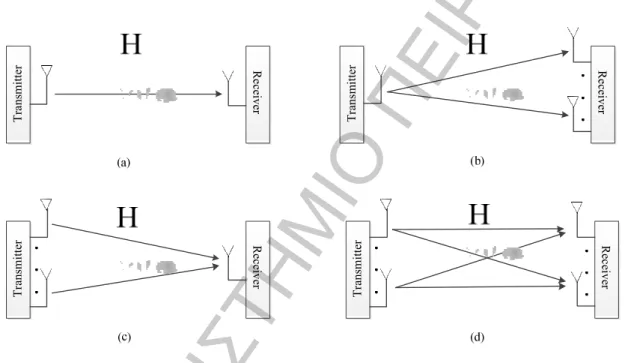
-1a) via several sufficiently separated satellites and one ground station equipped with several single polarization antennas that provide spatial multiplex coding of channels [33]-[36] and. iii) polarization techniques (Fig. 3-1b), where a single dual-polarized satellite communicates with a single ground station equipped with a dual-orthogonally polarized antenna that provides polarization multiplexed channel coding [25]–[32]. Polarization techniques represent a promising solution due to recent advances in compact MIMO antennas [37] and are intended to overcome potential space limitations and avoid potential drawbacks of multiple satellite constellations, i.e. wasting limited satellite bandwidth to transmit the same signal. , lack of synchronization in reception, scheduling problems, interference between symbols and high However, polarized MIMO can only increase throughput by a factor of two, while satellite diversity can result in an m-fold increase in capacity, where m denotes the number of satellites.
Furthermore, the on/off blocking phenomena and the highly correlated rain medium that dominates at frequency bands well above 10 GHz can degrade the performance of polarized MIMO. Other ionospheric and tropospheric effects are considered negligible at the L and S frequency bands, as explained in the corresponding section. Therefore, the multipath propagation due to the local scattering near the terrestrial mobile stations is of great importance only for satellite MIMO systems.
Note that the satellite and polarized MIMO can be combined using multiple satellites each using a dual polarization scheme.
Polarized MIMO over Satellite
The need for Polarization
Wave Polarization Theory and Analysis
- Antenna Polarization
- Cross Polarization Discrimination
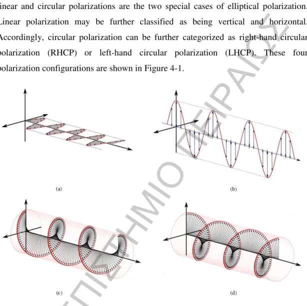
Another important parameter to mention is the polarization ratio of the electric fields. The ratio between the maximum and minimum polarized responses on the ellipse is the axial ratio. When considering polarized communications systems, the idea is to transmit separate data streams over each of the two polarizations of the wave.
Due to the interaction of the wave with the environment, the two components of the transmitted waves will rotate in the plane of polarization. As a result, each antenna on the receiver will receive a mixture of both transmitted signals. The rotation of the polarization plane occurs because the two rotating components of the wave move differently through the ionosphere.
Because an antenna is a passive electrical device, the radiation pattern through reciprocity can also be used to define the reception characteristics of the antenna. In that case, the radiation pattern describes the response at the output of the antenna when illuminated by an electromagnetic wave. However, the polarization of the waves that will be transmitted or received can also depend on the direction of transmission or arrival of the waves.
Depolarization refers to a change in the polarization characteristics of the radio wave as it propagates through the atmosphere.
Measurement Campaigns
- Conclusions
Isolation takes into account the performance of the receiving antenna, feed and other components, and the propagation medium. For the measurements, an Elektrobit Propsound broadband MIMO channel sounder was configured for a carrier frequency of 2.45 GHz, transmitting a direct sequence spread-spectrum signal produced from phase-shifted binary modulated pseudo-noise codes. The results regarding the received power versus FSL distributions for the co-polarized and cross-polarized components showed that the co-polarized channel components are larger than the cross-polarized components for the main road and suburban area and higher received power levels.
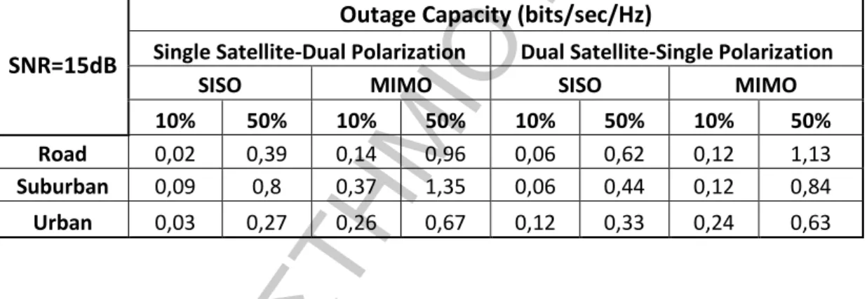
However, this difference is minimized for the urban area and cancels out with the lower received powers. A comparison is made between the capacity results from a SISO, and a dual polarized terminal antenna system (2x2 MIMO) with a single dual polarized satellite (DP-SS) to show the benefits of polarized MIMO over the satellite . Comparing the values between the SISO and MIMO case from Table I we can conclude that for the MIMO case the interrupt capacity was almost tripled.
By observing Figures 4-4 and 4-5, the single-satellite-dual polarization (SS-DP) system outperforms the dual-satellite-single polarization (DS-SP) for the MIMO case, suggesting that the use of dual polarization is more advantageous than implementing two transmitters. An interesting result obtained from the measurements is that capacity is smaller in urban areas, probably due to the increased strength of the LoS component and the spatial correlation introduced. Polarized MIMO over satellite | 43 Figure 4-4: 10% SISO breaking capacity for 15 dB SNR for all tested environments.
So are both local environmental propagation effects, e.g. multipath, shadowing and blocking due to the local environment near the terrestrial receiver, and tropospheric effects, e.g. precipitation, oxygen absorption, water vapor, clouds and precipitation, involved. .
Polarized 2x2 MIMO System Simulation
- System Model
- SISO LMS Sub-Channels
- Environment XPC and Antenna XPD
- Linear detection Methods
- Zero Forcing Receivers
- Minimum Mean Square Error Receivers
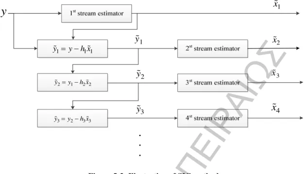
- Successive Interference Cancellation
- MATLAB Simulation
- From Theory to Implementation
Due to the local environment near the UT, the LOS link may be free, partially or completely blocked by, for example, trees or buildings, giving rise to multipath, shadowing and blocking effects, respectively. For modeling the envelope hij ( ,i j=1, 2) the Loo (or shadowed-Ricean) distribution is assumed because it has been fundamental for the construction of the SISO LMS channel model, which has been extensively used and validated in the recent standardization activity of DVB -SH. MP b is the average power of the Rayleigh-distributed envelope % hij of the small-scale fading components, and I0( )∆ is the modified Bessel function of first.
The large-scale attenuation components hij (,i j=1, 2) are related only to the interpolar discrimination of the antenna, denoted by XPDant, while the small-scale attenuation components. On the contrary, the XPD of the satellite antenna is assumed to be close to ∞ due to its practically very large value. If the transmitter knows the channel, there is an architecture called Singular Value Decomposition (SVD) that enables the transmitter to send parallel data streams along the eigenmodes of the channel.
Once a data stream has been successfully recovered using the methods described previously, it can be subtracted from the received vector and in this way reduce the burden on the receiver of the remaining data streams. If it is assumed that the data streams are well encoded and the block length is sufficiently large, then the probability that the streams will be successfully canceled is very high. Using MATLAB, several scripts have been built to evaluate the performance of the mentioned parameters each time using different scenarios, for example deploying ZF, MMSE, SIC-ZF or SIC MMSE receivers in different environments, such as heavy /lightly shaded urban, suburban, rural, tree line road etc.
The green and pink lines showing the theoretical SISO and AWGN SISO correspondingly are used as a reference for better understanding. Scalise, “In-depth analysis of the satellite component of DVB-SH: Scenarios, system sizing, simulations and field test results,” Int. Harles, “Measurement and Modeling of the Land Mobile Satellite Channel at Ku-Band,” IEEE Trans.