Ideas and concepts
What is it?
Just as the three-dimensional models (physical or digital) of the building mass offer cognitive help in grasping and evaluating formal characteristics, the same should be possible with similar models of spatial events. In order to create a practical digital tool that would be suitable for manipulating human events, both ends of the aforementioned activity spectrum scale must be considered within its inner mechanisms. This is achieved by introducing a distinct geometric element that represents the delimitation of the volume designated for a particular group of spatial events.
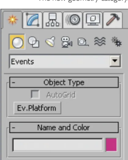
In the context of this research, the term event platform is used to describe a transparent, volumetric, digital representation of the intended spatial events in a specific space (Figure 411_02). It is top-down friendly as it encapsulates an improved version of the functional diagrams. The idea behind the introduction of Event Platforms is to provide the designer with a toolbox that can represent information about spatial events in architectural spaces.
For this to work correctly, it is crucial to maintain a clear division between the Event Platforms and the physical building parts of the structure (Figure 411_03). This fundamental independence of the two entity typologies (events and building geometry) does not prohibit the existence of connections and articulations between them. Event platforms ARE top-down friendly as they encapsulate an improved version of the simplified information of functional diagrams.
Because the typical functional diagrams were primarily created in the early design stages, it was imperative that their representation constantly change as the project evolved. The Event platforms, like their digital, parametric counterparts, are far better equipped to cope with the uncertainty and ambiguity of the non-linear design process. Contrary to the widespread use of the functional diagrams, lower human activity has almost never been part of the design process.
The event platforms leverage contemporary algorithmic processes to visualize and manipulate the intricate intrigues of human activity. One of the main characteristics of spatial events that contribute to their complexity is their temporal nature. The event platforms form the framework for capturing some of the temporal qualities of human activities.
How is it used?
With the introduction of event platforms, some additional parameters have been added to the existing set of options and settings. Within the context of three-dimensional digital modeling, Event Platforms provide computational representations of spatial event data as tangible and useful components that can complement the actual geometric elements of the design project. Parametric Functionality of Event Platforms Event platforms are computational components that are controlled by a different set of parameters.
At the same time, he is able to manipulate the volume of the platform by entering data about their height. To facilitate better integration within the design process, all Event Platforms size parameters can be set as flexible values within a certain range. All these relationships as well as the approximate location of the connection along the perimeter of each platform can be easily adjusted computationally (Figure 411_10).
The visual connectors include parameters that define how much of the surrounding context is visible to the avatars of each Event platform. Using the event platforms, as described so far, implies that, while the designer configures the settings of each platform, he manually manipulates and positions them in the model. The emergence of the Event Platforms offers the opportunity for a fresh perspective on the existing architectural visualization techniques.
The vast majority of currently used representations are solely focused on the exact depiction of the geometric shape. However, the representation of spatial events requires an expansion of current media to include the avatars as well as their movements and changes over time. The proposed software exploits the parametric nature of the event platforms to produce new visual and data representations of the design result.
In reality, films are nothing more than the visual interpretation of stories through the medium of the moving image. The proposed tool uses the positioning of avatars of event platforms and creates different digital cameras around them by following established cinematic conventions. The result of collecting more data from the model is the creation of data diagrams.
Why this tool will be effective
Technical documentation and examples
Technical documentation
This group contains all the parameters relevant to the size of the Event Platform (Figure 421_04). Just like the previous parameter group, the inactive spinner displays the current volume of the platform. Contextual: This checkbox determines whether the Event Platform is part of the contextual environment.
Future iterations of the plugin could have this parameter available to the designer. Position: This group of parameters controls the position of the physical connections along the perimeter of the event platforms. Add Link: This button closes the floating window and adds a new link to the event platform list box.
Within the user interface (Figure 421_13), there is a label list of all the available sides of the selected platform. At the bottom of the rollout there are two buttons (called "Update" and "Create Geometry"). This parameter group controls the way the software creates new configurations of the event platforms.
This rollout includes all parameters that control the visualization animation sequences of the event platforms. Pan Shots: These shots depend on the size of each event platform rather than the avatars. Size: There are two spinners that control the range of the size of the openings.
Rot.: The range of rotation of the polygonal openings is determined by these spinners. Col.: These spinners control the range of the number of columns in the case of raster-based scattering. Rows: These values determine the range of the number of rows in the case of raster-based scattering.
Example 1: Single Family Residence
The steep site elevations ensure that the plot has an unobstructed view towards the rest of the city and the sea. There is of course some flexibility when it comes to the surfaces of the different rooms, but... The first step of the process is to model the plot and urban contextual environment within the 3ds Max software (Figure 422_02).
In general, the goal of the plot modeling process is to efficiently capture the unique characteristics of each location. The modeling of the context is followed by the creation of the Event Platforms via the appropriate creation rollout. In addition to the platforms that represent the new spaces of the home, the architect must also create contextual event platforms.
The designer has the option to insert events in the selected platforms, based on the complexity of the project. After configuring the events, the platforms were ready to be placed inside the plot. In this example, each of the two manual solutions was given as an initial model for the automatic calculation algorithm.
By manipulating the settings and variables of the plugin, 5 different parametric panels were created (Figure 422_10). The second panel is similar to the first with the difference that the distance and thickness of the blinds in the same panel are variable. After creating the panel types, the next step was to introduce connections between them and the platforms.
A fifth data plot was added manually to compare the total values of the four configurations (Figure 422_23). In addition, the positioning of the avatars in the common areas has been modified to be more in line with the programmatic demands. The comparative critique of the new and the previous versions revealed noticeable improvements for both models.
Example 2: Office building
From the above list, it appears that the building program provides a considerable degree of flexibility to the designer's intentions. Within the 3ds Max software, the first step in the process is to model the plot as well as the urban contextual environment. In addition to the platforms that represent the new interior spaces of the building, the designer should also create contextual event platforms.
Given the complexity and multiplicity of connections, however, this may prove unattainable. In this scenario, the tool's algorithms keep the iterations with the most completed connections. The next step of the process involves introducing geometric elements that will be wrapped around the event platforms.
By carefully manipulating the plugin settings, 5 different parametric panels were created (Figure 423_09). However, the rear volume has insufficient lighting, as it is pushed to the rear edge of the plot. The main problem is the questionable choice of round windows for this specific context.
The feedback from the visualizations and the diagrams led to several modifications of the models. After completing the edits, a second batch of visualization animations and data charts was created. A comparison of the new versions with the previous ones shows a noticeable improvement for both models.
The final phase of the case focuses on the preparation of design material for the prospect's meeting. On the one hand, animations provide a much more dynamic and lively visualization of the building. This small group of 10 offices must be relatively independent from other offices.
Example 3: Company Headquarters
Evaluation
Future development. 221