Numerical results are presented and discussed regarding the details of the wave field and the power output of a single driver with vertical cylindrical body over a region of general topography. 75 Figure 81: Flow diagram of the method for solving 3D problems of floating bodies over variable seabed.
Facts and policies for climate change
The crucial indexes
3 and this requires the immediate fundamental transformation of the global energy mix in just a few years [3]. One of the significant outcomes is that the annual ice cover of the Arctic decreases dramatically (Fig. 4) and consequently the sea level rises, as indicated by the measurements of Table 1 and the relevant Fig. 5, 6 and 7, facts that the climate crisis.
![Figure 2: Energy consumption and GDP annual growth change (2006-2017) [2]](https://thumb-eu.123doks.com/thumbv2/pdfplayerco/334508.54095/34.892.181.707.120.393/figure-energy-consumption-gdp-annual-growth-change-2006.webp)
Redirecting to eco-policies
Therefore, green technology appears more ambitiously than ever before and gradually dominates larger quotas in the energy production market. In addition, it is also a way for countries to become self-sufficient in the energy sector through geographical distribution of its resources and consequent decentralization.
![Figure 9: Renewable energy electricity production (1990-2017) [1]](https://thumb-eu.123doks.com/thumbv2/pdfplayerco/334508.54095/38.892.150.745.425.1027/figure-9-renewable-energy-electricity-production-1990-2017.webp)
An ocean of potential
Power emerging from the seas
The wide range in estimating wave energy depends on each researcher's perspective and the highly dynamic wave physics. Levelized cost of energy (LCOE) estimates for wave energy are approximately $500/MWh and $440/MWh for tidal [15].
![Figure 12: The Orbital O2 (2 MW) tidal turbine by Orbital Marine Power (ex Scotrenewables) [16]](https://thumb-eu.123doks.com/thumbv2/pdfplayerco/334508.54095/41.892.118.790.151.295/figure-orbital-tidal-turbine-orbital-marine-power-scotrenewables.webp)
The wave energy technologies
A further attempt at categorization of the above main types of Wave Energy Converters (WECs) leads to this second level of classification according to the mode of operation [14,22]. The main principle for its optimization is the minimization of the reactive power on moving part of the WEC.
![Figure 16: Fixed structure OWC: (a) The Limpet project [23], (b) The Tapchan project [24]](https://thumb-eu.123doks.com/thumbv2/pdfplayerco/334508.54095/45.892.185.783.398.544/figure-fixed-structure-owc-limpet-project-tapchan-project.webp)
Capturing the wave power
The main advantage of ascent point absorbers is their independence from the directional spectrum of the incident wave field due to their axisymmetric body design and relatively small dimensions. The investigation of the lifting point absorber behavior and its power capture is the subject of many researches worldwide.

BEM introduction
Boundaries treatment
For problems with unbounded boundaries, the main difficulty encountered in numerical evaluations is the radiation condition, which expresses the energy losses and the physical damping behavior of the output signal away from its source. However, in the 2D wavelet problem evaluated in this section, the radiation state has an analytical Sommerfeld expression and its implementation is straightforward.
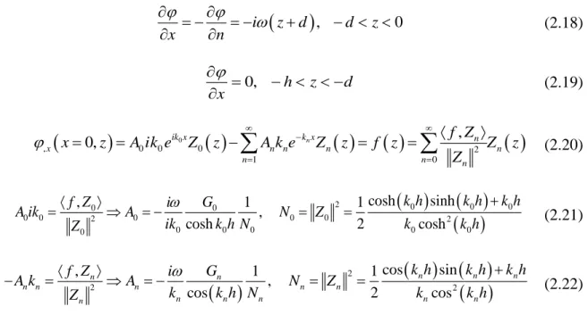
Mathematical formulation for the 2D semi-infinite strip problem
The solutions of the above system, described by the Eq. can be obtained with the variable separation method and appropriate algebra handling with the complex representation of the Φ-potential as: Φ(x,z;t)=Re{φ(x,z) ) e-iωt} and then reformulate the problem to An ordinary differential equation problem (ODE problem) in conjunction with its BCs. For n=0, this relation expresses a one-way connection between ω and k, which in this case is a real number and expresses the oscillatory component of the solution.

Analytical Treatment
On the other hand, the piston-type wavemaker oscillates horizontally with an angular frequency-ω and with a stroke-x0 and therefore generates harmonic waves of the same frequency. 46, the flap type wavemaker better approximates the intermediate and deep water depth conditions, while the piston type models shallow water conditions. The piston type causes a horizontal flow rate constant at each depth of the water column.
An example of the analytical solution of this problem both for the two types of wavemakers follows in the next figures 47, 48. The conditions are ω=1 rad/sec and h=1 m, and as a result h λ⁄ =0.1285, corresponding to intermediate depth conditions, conditions that both wavemakers can model effectively. From the above figures, it is obvious that for these depth conditions, the piston-type wavemaker achieves larger free surface potential values compared to the flap type, a fact that is justified by the mode of operation, the relative stroke of each wavemaker and the water displacement volume.
According to the volume of water displaced by each type of wave maker, a simplified theory was proposed was 1964 by Galvin [66]. The basic idea behind this theory is that the volume of water displaced by the wave maker in one stroke is equal to the generated propagating wave crest volume and is graphically described in Fig.
BEM-2D treatment
- Wavemaker problem BEM-2D implementation
- Wavemaker problem BEM-2D validation
The numerical evaluation of these integrals requires approximating the boundary of the domain with a simpler, more manageable geometry. The local coordinates consist of the axis-ζ parallel to (AB) and axis-η perpendicular to ζ. The system can be easily solved in a mathematical software with the inverse of matrix Ajk of the Eq.
A calculation algorithm is developed in the Mathworks MATLAB environment to implement the numerical method. The induced potential and velocities to the j-collocation point, which is the center of the j-element, from all i-center points are calculated by a short subroutine. This is the goal of using the radiation state that is responsible for the preparation of the final solution.
In practice, wave attenuation is achieved by building a beach that breaks the waves. The convergence graph (Figure 59) shows the importance of the trade-off between accuracy and computational costs.

Analytical treatment
- Radiation potential evaluation
- Hydrodynamic coefficients evaluation
- Froude-Krylov forces evaluation
- Total hydrodynamic forces evaluation
- Heave response evaluation
All other external forces should be included in the right hand side of the above equation. The right-hand side of the above equation is evaluated by taking into account that the Φ3 potential is axisymmetric, independent of the azimuth angle θ=tan-1(x2⁄x1) and thus: Φ3=Φ3(r,x3) where 𝑟 =√ (x1 )2+(x2)2 is the distance between the horizontal plane and the center line of the cylinder. Considering that the generalized normal vector is equal to: n3=0 on the vertical wetted surface of the cylinder and n3=1 on the bottom of the cylinder (x3=-T), the FK forces are given analytically by the following equation.
For the subdomain Di under the cylinder, the following equations are satisfied and BC:. 2.81) The general solution of the above system of equations can be constructed by the solution referred to. to the homogeneous problem of Eq. 2.80) and the solution to the inhomogeneous problem of Eq. A general representation of the solution to the homogeneous problem Φ3Η(r,x3) can be achieved by separating the variables in Di. At this point, the presentation of the solution described above meets all requirements except for two conditions:.
Another type of normalization is also applied in relation to the mass of the cylinder-M, which is a design variable of great importance, completely related to the hydrodynamic behavior of the body. The continuation of the assessment for the example shown in Figs 67, 68 is completed here with the following graphs (Figures 69, 70).

BEM-3D treatment
- BEM-PML 3D implementation
- Mesh generation
- PML optimization
- BEM-PML 3D validation
- BEM – Heave response evaluation
With the correct and consistent discretization of the boundaries, the numerical solution can converge and approach the analytical solutions whenever feasible. The cylindrical arrangement is ideal for representing the radiative behavior of the solution in diffraction and multiscattering problems. Choosing a very fine mesh on the body surface requires an exponentially larger amount of elements of the same size on the free surface and on the bottom and, due to the dimension of the problem, is inevitably limited by the computational cost.
In this particular study, an absorption layer technique inheritance from a defined activation length and with defined characteristics based on the perfectly matched layer model (PML) [76,77] is used. In this approach, wave damping is induced by a hypothetical part of the frequency (Eqs, which acts as a damping filter for waves without significant reflections. PML evaluation and optimization is a multi-parameter problem based mainly on five key parameters.
The PML efficiency requirement is quantified with the use of the relative error based on the L2 norm of the FS potential. For example, the evaluation of the hydrodynamic coefficients for two different meshes on the cylinder body, specifically 10x88 and 20x88, keeping the meshes identical on the free surface and on the bottom, approximate the analytical expressions differently, as shown in Fig.

Hydrodynamic problem formulation
Propagation problem evaluation
The Coupled Mode Model is an alternative technique to solve wave propagation problems over a varying seafloor, even with steep topography, where analytical solutions are not possible. The additional term φ-1(x) Z-1(z;x) is the sloped bottom mode, a correction tuning term that ensures the satisfaction of the Neumann BC on the seabed on every part of its profile, including the non-horizontal parts and the non-sloping parts, and influence the rapid convergence of the local mode series. Also supplemented with the essential BCs for reflection, transmission, and radiation of the wave, the CMS formulation is discussed in Appendix B, along with characteristic examples.
Diffraction-Radiation problems evaluation
Therefore, the BC on free surface of Eq. 3.17) reformulated again as before, with the implementation of a hypothetical part of frequency, expressed by the second formula in the bracket of Eq. The discrete solution is achieved using collocation method, by satisfying BCs at the center of each quadrilateral panel, distributed on all boundaries with mesh generation. By treating the self-induced quantities semi-analytically, as described in Appendix A, the induced potential and velocities from the pth element at any collocation point can be calculated by numerical quadrature.
Mesh generation
Numerical results
The evaluation of the performance of these proposed WECs will take place in the area under the. The damping coefficient of the Power Take Off system is a decisive parameter for the performance of the device. With the correct selection of the value, the performance index of the previous section will be significantly improved.
Again, the performance index curve will be plotted as a function of the PTO value. The design and optimization of this layout are critical tasks for the overall efficiency of the wave park. Furthermore, φkl is the radiation potential due to l-motion of the k-body satisfying BC:.
For the evaluation of the normalized power output by the device, typical PTO damping values are investigated. For the calculation of the induced velocity potential, even for twisted elements, the above formula is used. In general, the coordinates of the points 1, 2 and P will be given in the Cartesian system.
The induced forces and the output power of the device are calculated for an optimal reference case for the buoy.
