In case of any failure or non-compliance, the system will respond in accordance with predefined procedures according to the assessed level related to the risk of the event, thus reducing the severity and probability of the possible accident. The case study scenario is modeled for human-robot scanning system with industrial robot application.
Introduction
Human-Robot Interaction Domain
Research Motivation and Objectives
Safety System Description
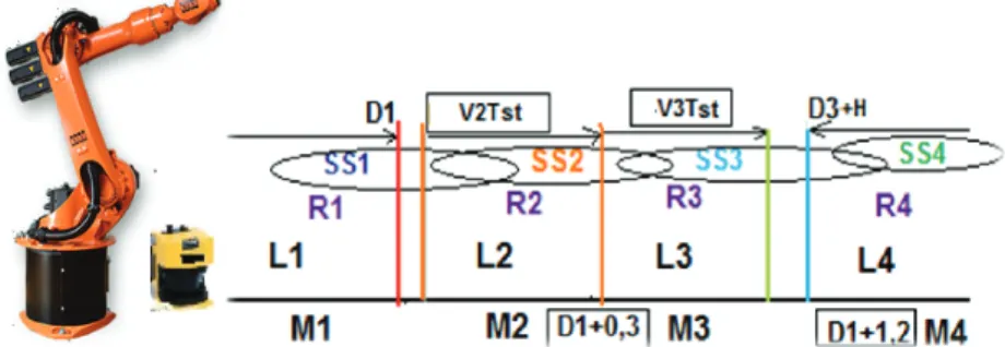
Safety criterion is mainly based on the developed in the research hazard index metric, which consists of force/acceleration and distance hazard evaluation measures. Therefore, there is no defined boundary in the safety elements transition control algorithms and their sets of features are overlapped.
Literature Review - Safety for Human-Robot Interaction
- Robot Related Hazards
- Robot Safety Standards
- Hazard Assessment Techniques
- Standardized Risk Assessment and Reduction Approaches
- Safeguarding Zones and Protective Means Identification
- Protective Solutions for the Interaction Level 3
- Protective Solutions for the Interaction Levels 1, 2
- The Role of Cognition and Ergonomics in HRI Safety
Another problem is the formulation of the forces applied to the robot in the operational space. This balance is influenced by the mutual weight of the human and the characteristics that meet the robot.
Safety Expert System
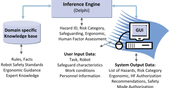
Safety Expert System Architecture
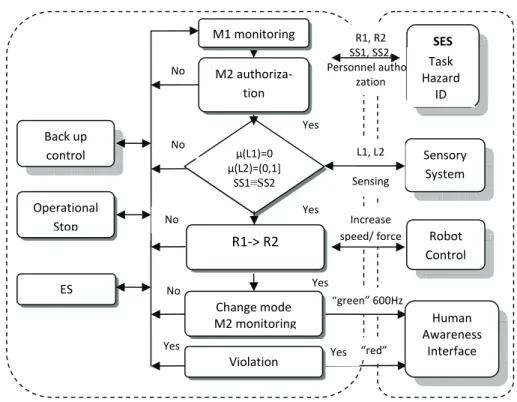
The analysis of the system is based on the different decision-making procedures stored in the SESs inference engine block (see Figure 3.3). It also authorizes the personnel who will be involved in the task (Worker Authorization) and provides an estimate of the working conditions (Ergonomic Analysis) and finally gives recommendations on further system improvements if necessary.
Task Analysis
- Levels of Interaction for Human Centered Robotics
- Hazard Identification
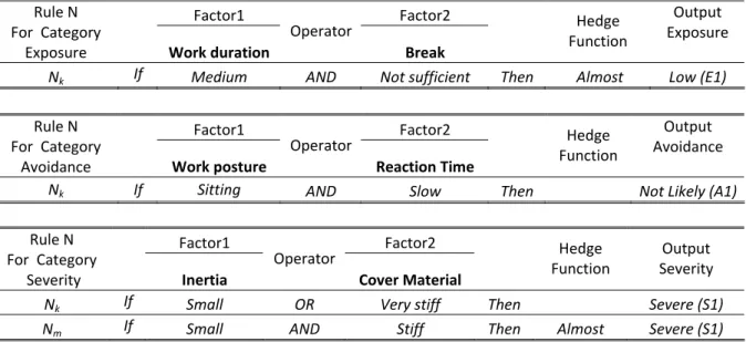
- Risk Assessment Algorithm (Fuzzy logic based Inference Engine)
- Risk Reduction
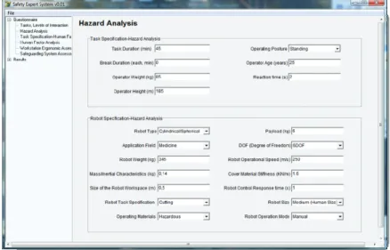
An example of the dialog screen is shown in figure 3.4. This information is also used later for risk assessment and definition of fuzzy sets. The risk assessment inference engine was built and interfaced using the Delphi system application.
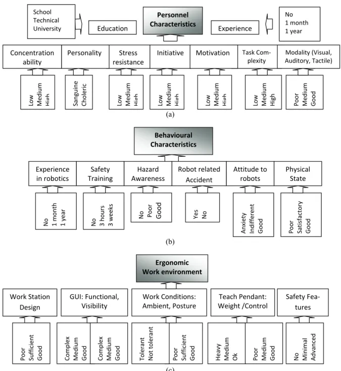
Ergonomic and Personnel Assessment
- Factors Rate Importance Evaluation Methods
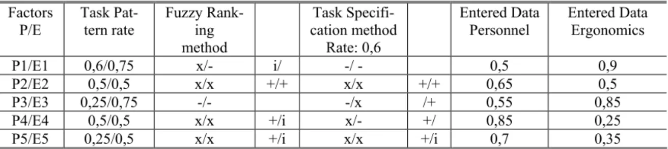
Modification of the factors and the assessed rates can only be performed in the Excel files. Tables 3.8 show the ranking scale for the factors related to the Personnel (a) and the Ergonomics (b) analysis, which development is based on the fuzzy ranking method. Tables 3.10 (a) and (b) illustrate the example of the estimate for the task "teaching" within the interaction Level 1.
Assessments based on the task-specific approach also showed inadequacies in the design of learning outcomes (E2).
Safety Criteria for a HRI Domain
Types of Injuries
The most serious injuries can result from the last impact type, where a head is exposed to maximum impact properties without any ability to compensate through back movement. Since it is not feasible to adequately treat all different contact types of injuries in this work, only blunt contacts are considered. The injury criteria can therefore be measured from the skull bone fracture, brain defect thresholds and pain tolerance measures, bearing in mind that the analysis is also performed for friendly human-robot interactions where even any discomfort must be avoided.
In this research, an injury severity scale is proposed, which formulation is based on a head injury/pain threshold correlated with the HIC criteria.
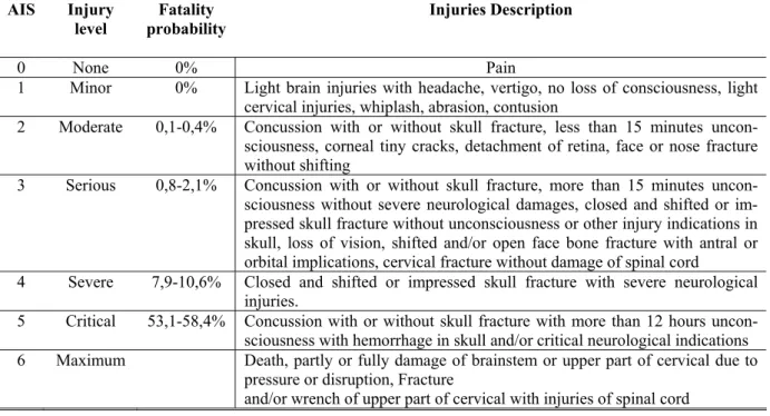
Standard Injury Indices and Scale (HIC, AIS)
Likewise, the resulting injury indices can be used to assess injury severity with further consultation of biomechanical expertise, such as e.g. To evaluate the likelihood of serious injury from a collision, an empirical formula was introduced by the automotive industry to correlate head acceleration with the severity of the injury, known as the Head Injury Criteria (HIC, which is calculated as the maximum integral of the resulting acceleration of the center). of the mass of the head during the crash. 4.1) In this expression, ah is the resulting acceleration of the human head and Δt is an impact period that should not exceed 15 ms (from Figure 4.3 a). Most research related to HIC criteria has been conducted on the basis of car crash test results.
Established in the automotive industry indices are therefore not always applicable to a human-robot interaction domain in light of the much lower operating speeds and severity of impact.
Robot Danger Index Approach
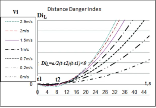
- Distance Related Criterion Introduction
- Force and Acceleration Related Criteria Development
- HIC criteria Integration
- Collision Modeling
- Manipulator Effective Mass Evaluation
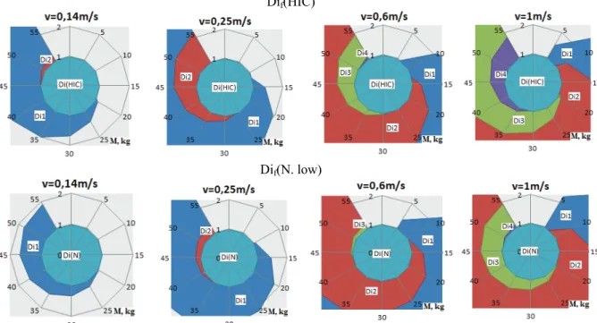
- Critical Values and Robot Injury Severity Scale Definition
However, given the fact that the robot (here) has a very high stiffness (250 KN/m), the damping ratio becomes very small (10−4) and does not contribute significantly to a hazard index value. Substituting this relation into the general form of the risk index (4.2), a new risk criterion can be given: The large-scale properties of the robot manipulator at the moment of impact can be compensated by the reduction of the operating speed and vice versa.
Therefore, the matrix M(q) can be calculated as:. 4.33) Replacement with what is specified in the table in fig.
Discussions
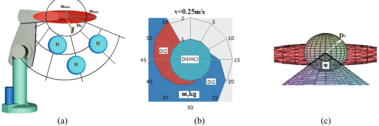
However, it is clear that the absolute maximum cannot be reached since the existence of the robot with a very small stiffness and negligible effective mass is quite improbable. An optimal velocity-mass ratio for interactive tasks was defined for the velocity 0.25m/s with effective mass 25kg, which also correlates with the robot safety standard requirement to maximum speed. The proposed approach can be effectively used to identify the range of the robot operating parameters for different levels of interaction.
For example, manipulator-related parameters (rigidity, speed and effective mass, etc.) can be controlled based on the injury severity curves associated with the interaction level to achieve the required level of safety.
Path Planning and Control Strategies with DI Application
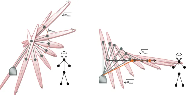
Another possible application of the DI is to define an area of the robot operating space where the human presence or approaching area is relatively safe (see Fig. 4.22 a). If the user suddenly moves closer to the robot, the potential collision impact force will be much higher than if the robot was in a low inertia configuration. Minimizing the hazard criterion during the planning stage ensures that the robot is in a low inertia configuration when the collision occurs.
Once the path for the robot's movement has been generated, the velocity profile along the trajectory can be determined.
Danger Index Control Integration Methods
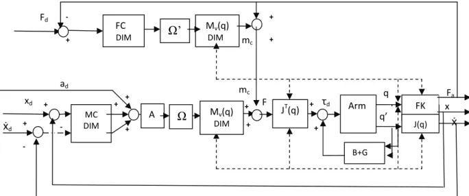
Danger index module (DIM) is integrated in the power control block, which enables online monitoring of the error resulting from the difference between desired power and its actual value. In the proposed solutions, only robot controller output characteristics are involved in modification according to the hazard index approach without interfering with its internal operation. The hazard index-based safety module described in this chapter provides a methodology to ensure human safety during a human-robot interaction.
The risk index module in the control algorithm is proposed as a separate unit, which independently monitors the kinematic and dynamic properties of the robot, the proximity of personnel (PSD) and other characteristics of the protective system (SS).
Safety Mode Controller
- Approach Overview
- Safety Modes Evaluation
- Modes Categories and Functional Domains
- Conditions for the Safety Modes Transition
- SMC and Safety Criteria Integration
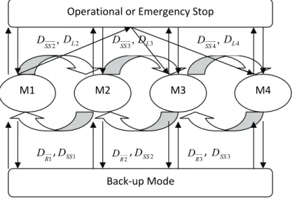
Boundaries for the domain related to the robot (DR) and its set (Ri) are evaluated based on a hazard index approach, where the parameters of the robot, e.g. The method of termination depends on the hazard of the operation and the degree of interaction. An example of the integration of safety measures is given for the PUMA robot with performance characteristics discussed in Chap.
It is assumed that the working space of the robot (d1) is 0.6 m, while the maximum elongation of the PUMA robot arm (d2) is about 1 m.
Human Awareness Interface
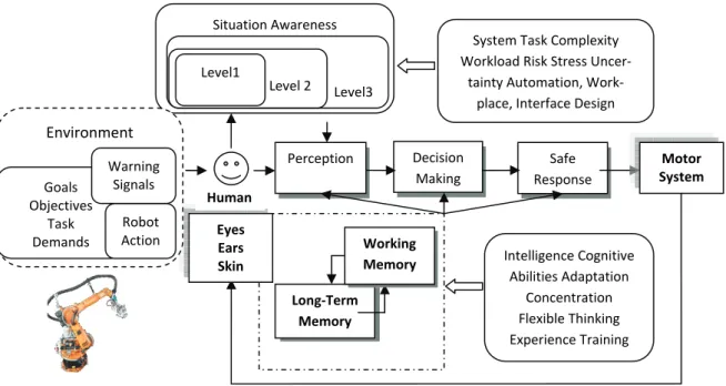
Situational Awareness and its Role in HRI
Cognitive science studies would be essential to create a better understanding of the human attention mechanism, which enhancement would significantly reduce the potential for error. These systems usually require advanced, sophisticated support devices to maintain situational awareness at the appropriate level, but these solutions still rely on the personnel's own attention, skills and concentration abilities, which can be easily influenced by a number of factors. Therefore, the most reliable and simple solution should be found by increasing the staff's perceptual abilities to the warning signals at the time of the danger, regardless of the current cognitive or physical state of the staff.
Human Nature Presentation. Abilities and Constrains
- Reaction Time Effect
- Human Perceptual Modalities
However, in robotic work cells, the operator is often exposed to the high level of noise generated by the robotic mechanisms or other machines, which can cause simultaneous simultaneous simultaneous stimuli that may exceed the capacitance channel for this modality. There is potential competition between visual attention and other cognitive tasks for limited working memory capacity, additional sensory cues can reduce the demands of visual attention on working memory, and attention is focused on only one of the presented objects. To develop an augmented human awareness interface, it was chosen to transmit the warning signals through the combination of visual and tactile signals.
Despite the fact that the information about a dangerous situation is represented by 2 stimuli (tactile, visual), which usually means 2 alternatives, due to the fact that each cueing provides the same information and requires the same response, it does not result in an RT -increase or in any signal recognition ambiguity.
Awareness Interface design
- Related Studies
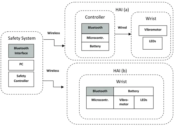
- Interface Architecture and Constituting Elements
- Operation Algorithm and Integration to the Safety System
Since the speed and amplitude of the vibration are directly related to monitoring the vibration waveform, an accelerometer can be used. Keeping the vibration source in good contact with the body is a major problem, so the vibrator(s) must be placed fairly close to the body. The main function of the notification interface is to immediately warn the operator of the dangerous state of the system through tactile/visual signals with different signal intensity/color depending on the severity of the danger of the case and the predefined response framework.
The specification of the range of intensity and type of stimuli is based on the Weber Fechner law and hand sensitivity thresholds.
Integrated Safety Monitoring System for HRI Domain
Safety Elements Interconnection (SES, SMC, HAI)
- Safety Monitoring System Functional Algorithm
Else
Safety criteria for the robot-related and distance-related parameter definition were taken from the example given in the tab.
Case Study Scenario Modeling
- Task Description
- Robot Trajectory Planning and Safety Criteria Evaluation
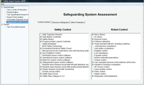
- Safety Expert System Assessment and Safety Modes Evaluation
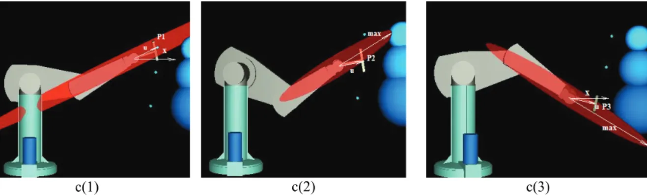
Analysis has been provided with the assumption that the scanning process is performed at three locations (points): P1, P2 and P3 (see Fig.7.5) The robotic human approaching "safe" configurations is defined as shown in Fig. In the robot motion planning, to avoid violating the safety criteria, the continuous move from point to point must be performed with the linear interpolation. The majority of the security systems are already embedded in the KUKA robot and control system.
Transition is only allowed between modes M2 and M3 according to the flow diagram shown in fig.
Conclusion
Thesis Summary and Contributions
The main basis for the estimates is a modeling of human-robot collisions, the thresholds for head injury (cranial fracture, pain) and the likelihood of serious injury occurring. A metric formulated for hazard level estimation in the human-robot interaction domain for use in path planning and control strategies. The safety mode controller is integrated into the overall safety system as an independent unit that makes it possible to ensure the reliability of the decision-making procedure.
The safety mode regulator is integrated into the entire safety system as an independent unit and is intended to ensure the reliability of the decision-making process.
Future work
Hirzinger, The Role of Robot Mass and Velocity in Physical Human-Robot Interaction – Part I: Open Unconstrained Effects, in IEEE International Conference on Robotics and Automation (ICRA), Pasadena, USA, 2008. Hirzinger, The Role of Mass and robot speed in physical human-robot interaction - Part II: Open unconstrained influences, in Proc. Burdick, Dynamic Exact Model and Inertial Parameters of the PUMA 560 Arm Robotics and Automation, Cont.
The Task worksheet consists of groups of tasks (Task n), defined for each interaction level (Ln) and performance description.