Global Software Development (GSD; also known as Global Software Engineering (GSE) and Globally Distributed Software Development (GDSD)) has become the main trend in the field of software engineering. Many specialists recognize globally distributed software development as more complex than even the most complex project managed entirely in-house [8], [6].
Data Sources
Data Analysis
Refining the dependencies between the new problems and tagging the categories with the sources was done through selective coding. Due to the industrial background of the research, customer-related questions were also omitted after data analysis.
Results
3 Particularities of GSD Projects
Global Factors
Indeed, they demonstrate the peculiar nature of globally distributed software development and indicate the forces that act as obstacles during a project. Therefore, we emphasize the uniqueness of globally distributed environments and highlight that awareness of global factors inherent in the nature of globally distributed project environments can help practitioners either reduce the likelihood or magnitude of unexpected negative outcomes.
Global Threats
Global factors inherent in the nature of GSD projects are recognized as root global threats that can jeopardize the success of a global project. Each of the global factors and their combination causes different threats and conditions for negative results.
4 Outcome Predictions in Global Projects
- Basic Concepts
- Approach to Calculate Outcome Predictions
- Survey Overview
- Survey Data Analysis
- Risk Barometer
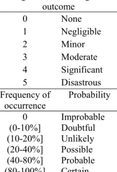
Freq (t, ci,j) – frequency of occurrence of the negative outcome of the certain level of the certain threat;. Magnitude of the negative outcome of each threat is evaluated using a linear scale or its equivalent [None, Negligible, Slight, Moderate, Significant, Disastrous] as described earlier.
5 Discussion
Particularities of Global Projects
Furthermore, practices adopted for global risk mitigation will act as a counterforce to global threats and reduce the impact of global factors and threats on project outcomes (see Figure 4). The magnitude of the impact of global factors and threats on project outcomes shows that they can indeed drive projects to failure if not managed in time.
Application of Risk Barometer
The Global Threat List provides guidance for effective risk identification and shows the different ways global factors can operate. Global threats can lead to a significant negative impact on the project budget, cause schedule deviations and customer dissatisfaction.
Conclusions
12] Smite D., Borzovs J., „A Framework for Overcoming Supplier Related Threats in Global Projects“, In Proceedings of the Int. 13] Smite D., “Project Outcome Predictions: Risk Barometer Based on Historical Data”, In Proceedings of the Int.
Application of Smart Technologies in Software Development: Automated Version Updating
1 Introduction
The other approach foresees that developers ensure the use of software in various environments and their combinations. In fact, all efforts to develop "universally applicable" software result in developing technical solutions for each of the environments.
2 Software Life Cycle Models and Smart Technologies
The objectives of the self-adaptive software [3, 4] partly overlap with the principles of the smart technologies. A detailed analysis of the characteristics of smart technologies can serve as the subject of a separate research paper.

3 Automated Version Updating
- Environment Test
- Installation of Software Version
- Installation of the latest version on the server
- Identification of parameters of the latest version
- Comparison of software versions
- Downloading and installing new components
- Data Migration
- Self-Testing
- Back-up Administration
- Use Cases
- Indications for further research
The system downloads the necessary packages of the latest software versions and installs them on local workstations. Self-testing must be possible at almost any moment of system operation without disturbing users.
Acknowledgements
However, the mechanisms of intelligent technologies need regular adaptation to environmental changes, especially in the case of standardized software. The opportunities offered by intelligent technologies pay off and improve software delivery and user support even if a company has only two geographically separated subdivisions.
Towards a Semantic Execution Environment Testing Model
The paper is further organized as follows: the next chapter describes the background of the research and poses the research questions.
2 Background
Systems Interaction
For example, the organization's customer data can be shared between the CRM (Customer Relationship Management) software system. The integration can be performed by using public interfaces of the hosting system – an API (Advanced Programming Interface), if one exists, or by using internal mechanisms of the host system.
The Research Question
Performance requirements may vary from system to system, and some of them may be conflicting. Of course, the interface that the host system provides and the guest systems depend on may change over time.
3 Related Work
Self-Healing Systems and Built-In Tests
Here, the authors define a term "maintenance mode" [6] for a software system, which is proposed as a special execution mode of the system when built-in tests can be activated, but the business functionality of the system is not touched. Authors of the paper suggest that BITs are used to test whether the component is capable of operating the defined interfaces, ie.
Unit Testing and Test-Driven Development
Authors of [6] suggest that a component should contain one or more BITs that can be executed; and implement a specific interface to be called when the system is running in maintenance mode. It is noteworthy that the authors mention the importance of “Quality of Service” (QoS) testing for the verification of the operating environment, but their proposed model focuses on testing the contracts between the components. Therefore, QoS testing is a “by-product”.
Similar Ideas in Hardware Appliances
During initialization, the camera checks whether the card is currently available, the type and capacity of the flash card. The idea of this paper is similar to the methodology described here - checking whether the external components relied on by the system under test fulfill their tasks.
4 The Proposed Model
- Model Summary
- Motivation for the Proposed Model
- General Architecture of Runtime Validation Framework
- Execution Requirements and External Verification Modules
- Kinds of Data Employed by the SWP Framework
- Creating a Software Profile Document
When the kernel is loaded, it finds the software profile document of the system under test and analyzes it. For a complete list of the essential elements of the Software Profile Framework (hereinafter SWPF), it is necessary to mention the EVM - External Verification Modules.

5 First Practical Experience
Therefore, the items in the inventory list have a property that describes the request XML node name that the current EVM can handle. Some of the computers tested did not have the required short date record, all of them had Windows XP SP 2 installed.
6 Conclusion
In: Proceedings of the Third European Conference on Software Maintenance and Reengineering, IEEE Computer Society, Washington, DC, USA. In: SERA '06: Proceedings of the Fourth International Conference on Software Engineering Research, Management and Applications.
Use of Design Patterns in
PHP-Based Web Application Frameworks
1 Introduction
2 Problems in the Use of Design Patterns
- Design patterns
- Properties of Design Patterns
- The Specifics of Web Applications
- Positioning the Problem
- Benefits from Researching the Existing Situation
- The Method for Studying Design Patterns
Therefore, an examination of several projects can lead to the discovery of general trends in the use of design patterns. Is the use of design patterns in the source code shown openly or is it hidden and therefore difficult to identify.
3 The Research Object
- Design Patterns Used in the Research
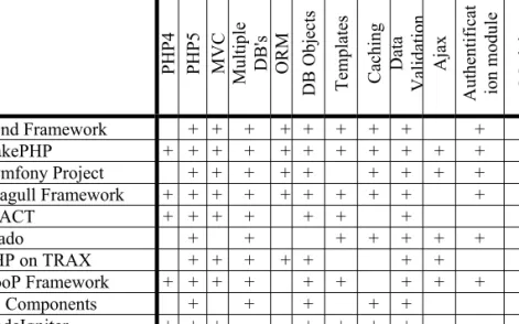
- Frameworks Used in the Research
- The Results of the Study of Frameworks
- Mention of Design Patterns in Documentation
- Mention of Design Patterns in Source Code
- The Timeframe of the Research and Evolution of Frameworks
- alpha alpha
- Conclusions on the Use of Design Patterns
- Additional Observations
In other words, we evaluated the use of design patterns, not the frameworks within which the design patterns were used. Among frameworks in terms of using design patterns, Seagull Framework is the leader with 18 design patterns.
4 Conclusions
More accurate use of design patterns would make it easier for new participants to get involved in projects. Using design patterns is something like a production line, and the creativity of the software designer can only be applied to the details.
Appendix A: Design Patterns
Proxy "Provides access to an object through a surrogate object to enable delayed instantiation or protection of subject methods." Visitor "Defines an algorithm as an object that "visits" each member of an aggregate that performs an operation.
Appendix B: PHP Frameworks
Php On Trax (formerly Php On Rails) is a web application and persistence framework based on Ruby on Rails and includes everything needed to create database-backed web applications following the Model-View-Control separation pattern. The controller processes the incoming requests (such as Save New Account, Update Product, Show Post) by manipulating the model and sending data to the view.
MDA AND MODEL TRANSFORMATIONS
The Base Transformation Language L0+ and Its Implementation
1 Introduction
Most textual model transformation languages are declarative languages that also have some type of model definition facility. However, research in the field of model transformations and effective implementation of model transformation languages is still current.
2 The Base Transformation Language L0
- Basic Ideas
- Precise Definition of L0
- Object-Oriented L0 constructs
- Example of an L0 Transformation
- L0 and Higher Level Model Transformation Languages
If

3 An Extension of the Base Transformation Language L0 – Metamodel Processing Constructs
Choosing Metamodel Processing Constructs
To obtain the value of an attribute of a previously unknown type, a special form (in which the attribute name is given as a String variable) of the get attribute value command must be used. Note that for Void pointers, this is the only way to receive the attribute value.
The Definition of Metamodel Processing Commands
- Metamodel Building Commands
- Meta-Model Element Scanning Commands
If these attributes are not present, The values of lt;strVarClNameOut> and
4 Implementation of L0+
Selection of the Runtime Environment
If there is a generalization relationship between the specified classes, execution control is passed to the next command, otherwise execution control is passed to
Compilation Schema
The main advantage of using this repository is that there are close counterparts for a substantial portion of the L0 and L0+ commands in the repository API. The implementation of the L0_Var_2 class is based on model processing functions from the Repository API.
Elementary Tracing Facilities
Each L0+ command is mapped to a C++ function that relies on the metamodel processing functions from the Repository API. To implement this functionality, some code fragments are added to the generated C++ code to record the program's activities.
5 Conclusions
The implementation of MOLA to L3 compiler, Scientific Papers University of Latvia, "Computer Science and Information Technology", 2008. Communication of the 7th International Baltic Conference on Databases and Information Systems (Baltic DB&IS pp.
Model Transformation Languages L1, L2, L3 and Their Implementation
2 Model transformation language L0
- Command of the Transformation Language L0
- return – returns the control to the calling program;
- DEBUG_ON – turns on the debugging mode;
- DEBUG_OFF – turns off the debugging mode
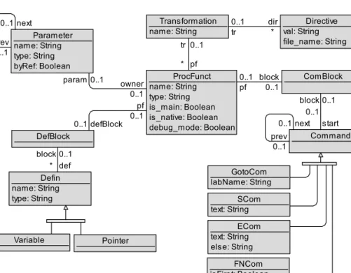
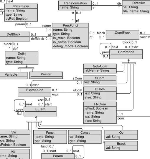
- The Metamodel of the Language L0
- Model Transformation Example in the Language L0
If pointer
3 Model transformation languages L0’ until L3
Transformation Language L0’
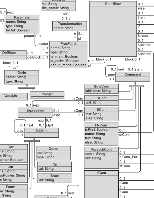
The metamodel of L0' is created by taking the metamodel of L0 and supplementing it with some new classes and associations. The only difference is in those places where a binary expression could appear in the L0 language – now an expression of arbitrary length is allowed in the L0' language.
Transformation Language L1
If the set is found to be empty, control is assigned to the tag specified in the "other" branch (if any). 2) When you reach a "next" command with a
The Comparison of L1 and a First-Order Logic
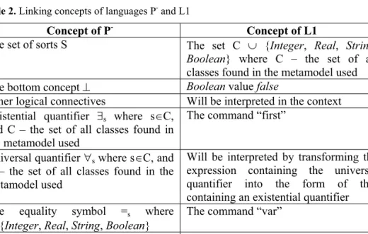
The equality symbol =s where sC and C – the set of all classes found in the metamodel used. For every formula of the predicate language P-, there exists an initial-final expression in the language L1 with the same truth value.
Transformation Language L2
The semantics of the "suchthat" block is the same as in the case of the language L1. Since this block is optional, the semantics of the "foreach" command is as follows - every instance of the specified class that matches the given pattern (if such exists; . otherwise, every instance is considered to be taken) is traversed and all the commands of the "do" block are executed for it.
Transformation Language L3
Since the "else" part is optional, it is possible that no commands should be executed in case of false value of the condition. A complete syntax definition of the transformation language L3 based on Backus-Naur notation [12] is given in Appendix A.
The Main Principles of the Implementation of L0’ Until L3
The main question about the L0' to L0 compiler is whether it is possible to build an equivalent construction in L0 for every arithmetic expression from L0'. A label of the form “___L_i” is considered a new label that cannot be found in an L0' program written by the user.

Main Problems of the Implementation of L0’ Until L3
The answer is even more obvious in this case than in the previous ones - each branching construction can be simulated using "goto" and "label" commands in a standard way (Table 7). Moving on to the next step – the compilation of L1 – a problem arises – a compiler processes the first of two instance finder commands mentioned above and then deletes the pattern definition block from the metamodel (to make the model refer to the L0' program).
In the case of the L0 compilation, some new variables may appear which must be unique within the scope of the entire specific procedure/function. For example, it can be useful in cases where L3 is used as an intermediate language in the compilation of a higher-level language, as is done in the compilation of the graphical model transformation language MOLA [15] – there is no need to perform any initialization tasks, nor the “lexems for L3”.
5 Conclusions and future work
Proceedings of the 7th International Baltic Conference on Databases and Information Systems (Baltic DB&IS'2006), Vilnius, 2006, pp. Kalnins, The implementation of MOLA to L3 compiler, Scientific Papers, University of Latvia, “Computer Science and Information Technologies”, 2008.
Appendix
L3 syntax definition based on Backus-Naur notation
Note – the non-terminal
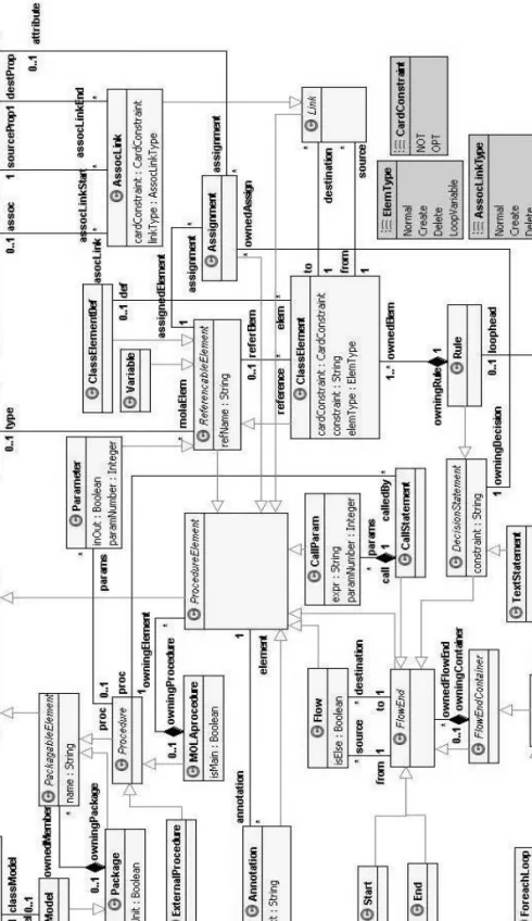
The Implementation of MOLA to L3 Compiler
TLTL
Most of the model transformation languages rely on an EMOF-compatible metalanguage to define metamodels. The general architecture of the MOLA compiler and a brief overview of model-driven compilation are given in chapter 5.
2 MOLA Language
Part of the actions also consists of class elements and bindings, but these are usually creation actions - the corresponding instances and bindings must be created. The loop head is a rule that contains one specially marked (with a bold border) element - the loop variable.
3 Previous Realizations of MOLA
A loop is executed while there are instances to iterate over, then the next construct is executed according to the control flow. The next step in the realization of the model transformation language MOLA was to search for a solution that meets the requirements mentioned above.
- Lx Metamodelling Facilities
- Language L0
- Languages L0’ – L3
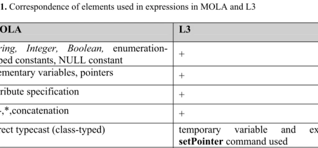
- MOLA and L3
These operations can be mapped to attr inst.

5 Architecture of MOLA Compiler
Implementation of the Lx Language Family
MOLA Compiler
Even less, only the actual code generator in the L0 compiler needs to be rewritten - the lexical and syntax analyzers can be reused. The final compiler (L0 for code) depends on the programming language that implements the model store API, but for most programming languages it is already built and free or open source versions are available.
Model-Driven Compiling
Since graphical language programs are stored as models, the first step can be omitted—the model-to-model transformation that a compiler implements can be applied directly. In this case, a standard parser can be used to obtain the "coding" pattern.

6 Mapping from MOLA to L3
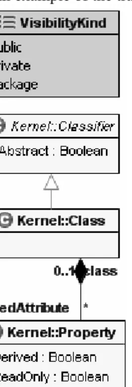
Mapping of Metamodelling Languages
The will block also contains a goto command for the label command of the code block that is generated by the MOLA statement associated with the output stream from the circuit header control. The last command in the main code block is a goto command in the label command of the code block that is generated by the MOLA statement bound by the loop's exit control flow.
Mapping of MOLA Statements
- Call-Statement
- Text-Statement
- For-each loop
A loop condition is expressed using the loop header pattern, which contains a special class element - the loop variable. The loop condition is translated into a so-so foreach block.
7 The surrounding of the MOLA compiler
Error handling in MOLA
Structuring a program in MOLA
Debugging in MOLA
Some debuggers have the ability to change the state of the program while it is running. Since graphical languages are usually represented in diagrams, an animation of the program execution is required.
8 Conclusions and Future Work
Proceedings of the 18th International Conference, OOPSLA'2003 (Workshop on Domain-Specific Modeling), Anaheim, California, USA, October 2003, pp In: Proceedings of the 1st ECOOPWorkshop on Domain-Specific Program Development (DSPD), 3 July. Nantes, France.
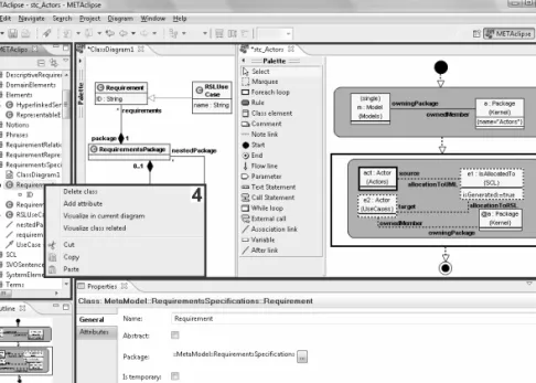
Technical Solutions for the Transformation-Driven Graphical Tool Building Platform METAclipse
In METAclipse, there are no restrictions on the correspondence between the domain and presentation metamodels. The emphasis of this paper is on the structure and functionality of the METAclipse framework itself.
2 Overall METAclipse Architecture
Basic Principles of the METAclipse Framework
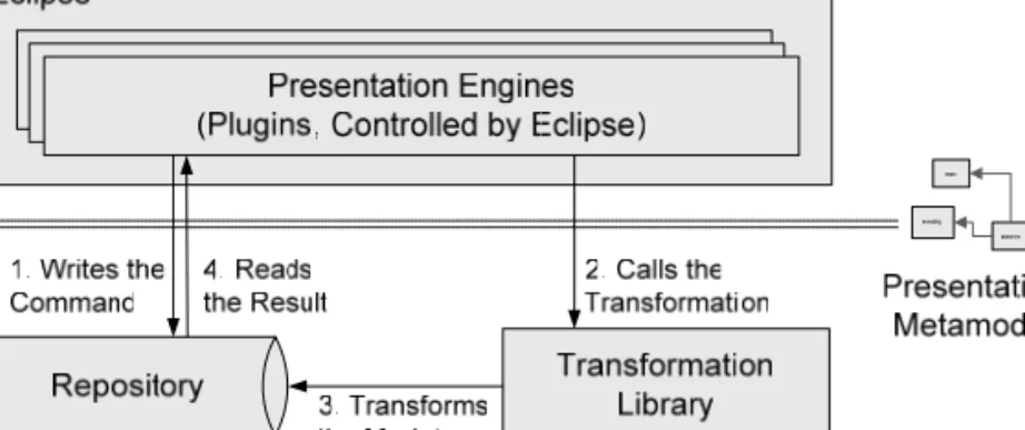
Let's imagine that someone has right-clicked on the node called "menu" in the tree, and the project tree engine has written the ShowMenuCommand instance to the repository (step 1 in Fig. 1). 2 is the part of the presentation model, showing the cases involved in handling the right-click event.
Solutions Chosen for the METAclipse Implementation
The refactoring will detect that the ShowMenuCommand has been written to the repository and will create instances of the presentation metamodel (not shown in Figure 2) that contain the necessary context menu (step 3 in Figure 1). Finally, Eclipse will regain control and the rendering engines will be notified of the changed model elements.
3 Interaction with the Repository and Transformations
Repository Interface
MOLA transformations are currently compiled against the MIIREP repository, which was developed in C++ and released as a Windows DLL file. This implies that the implementation of the MIIREP repository interface currently used in METAclipse (see Figure 3) uses a JNI (Java Native Interface) wrapper for the repository operations (see [30] for information on JNI).
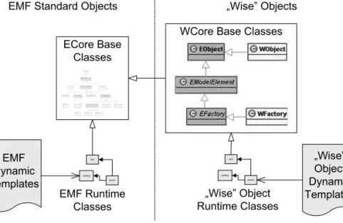
The Link Between Eclipse and the Repository: “Wise” Objects
To be able to read and write repository data, "smart" objects must have an opportunity to map classes, attributes, and associations to corresponding repository objects. However, tracking changes to existing objects had to be included in transformations.
4 Presentation Engines
- Presentation Metamodel Structure
- Interaction between the Transformations and Engines
- Project Tree Engine
- Menu Engine
This results in activation of the project tree engine (discussed in more detail in Section 4.3). When a METAclipse project is opened, the Project singleton is first used to find the ProjectNode instance, which is then interpreted as the root of the project tree.