Body Composition
Procedures Manual
Table of Contents
Chapter Page
1 Overview of Body Composition ... 1-1 1.1 Overview of Dual Energy X-Ray Absorptiometry ... 1-1 1.2 Risks ... 1-2 1.3 Personnel ... 1-3 1.4 Flow of Body Composition ... 1-3 2 Equipment/Supplies/Materials ... 2-1 2.1 Description of Equipment for DXA ... 2-1 2.1.1 Hologic Discovery A ... 2-1 2.1.2 Discovery QDR System Operations ... 2-3 2.1.3 Supplies ... 2-3 2.1.4 Radiation Badges ... 2-4 2.2 Maintenance and Repair of Equipment for DXA ... 2-4 2.2.1 Maintenance and Repair Reports ... 2-5 2.3 Calibration of Equipment for DXA ... 2-7 3 Protocol ... 3-1 3.1 Introduction to the DXA Examination ... 3-1 3.2 Explanation of the DXA Examination ... 3-1 3.3 Discovery A Table and Discovery QDR System
Operation ... 3-2 3.3.1 Startup Procedures for Hologic Discovery A
Table (Start of Session) ... 3-2 3.3.2 End of Session Shutdown Procedures for
Discovery QDR System ... 3-5 3.3.3 End of Day Shutdown Procedures for
Discovery QDR System ... 3-6 3.4 Examinee Preparation for the DXA Examination ... 3-7
3.4.1 Measurement of Weight and Height to
Determine Body Mass Index ... 3-7
Contents (continued)
Chapter Page
3.5 Whole Body DXA Scan ... 3-11 3.5.1 Selecting an SP ... 3-11 3.5.2 Selecting the Type of Scan ... 3-12 3.5.3 Positioning the SP ... 3-13 3.5.4 Reflection Positioning ... 3-15 3.5.5 Completing the Scan ... 3-17 3.5.6 DXA Scan Data ... 3-19 3.6 Proximal Femur Scan ... 3-20 3.6.1 Selecting the SP ... 3-20 3.6.2 Selecting the Type of Scan ... 3-20 3.6.3 Positioning the SP ... 3-22 3.6.4 Positioning the C-Arm and Aligning the Laser ... 3-23 3.6.5 Scanning ... 3-25 3.6.6 Panniculus (Belly Fat Pad) ... 3-27 3.7 AP Lumbar Spine Scan ... 3-28 3.7.1 Selecting the SP ... 3-28 3.7.2 Selecting the Type of Scan ... 3-28 3.7.3 Positioning the SP ... 3-30 3.7.4 Positioning the C-Arm ... 3-31 3.7.5 Scanning ... 3-32 3.7.6 DXA Scan Data ... 3-35 4 Data Entry Screens ... 4-1
4.1 Shared Exclusion Questions... 4-1 4.2 Weight/Height Entry Screen ... 4-6 4.3 Screening and Safety Questions ... 4-8 4.4 DXA Whole Body Data Capture Screen ... 4-13 4.5 DXA Proximal Femur Data Capture Screens ... 4-19 4.6 DXA AP Lumbar Spine Scan Data Capture Screens ... 4-22 4.7 DXA Component Status... 4-24 4.8 Session Pickup List ... 4-28 4.9 Session Preview Report ... 4-29 4.10 Room Log ... 4-30 4.11 Close Exam ... 4-31
Contents (continued)
Chapter Page
5 Referrals and Report of Findings ... 5-1 5.1 Observation Referrals ... 5-1 5.2 Report of Findings for DXA ... 5-3 5.2.1 Sample Preliminary Report of Findings ... 5-4 6 Quality Control ... 6-1 6.1 Equipment and Room Setup Checks ... 6-1 6.1.1 Daily ... 6-1 6.1.2 Three Times Per Week (1st, 3rd, and 5th days of
work week) ... 6-2 6.1.3 Weekly ... 6-2 6.1.4 Start of Stand ... 6-2 6.1.5 End of Stand ... 6-3 6.2 Procedures for Completing QC Scans ... 6-3
6.2.1 Hologic Anthropomorphic Spine Phantom
(HASP) ... 6-3 6.2.2 Step Phantom ... 6-10 6.2.3 Radiographic Uniformity Test ... 6-13 6.2.4 Slim-Line Whole Body Phantom ... 6-19 6.2.5 Hologic Femur/Hip Phantom (Weekly Scan) ... 6-23 6.2.6 Circulating HASP (HSP Q-96) ... 6-27 6.2.7 Circulating Block Phantom (Hologic Block
Phantom NH #1) ... 6-27 6.2.8 Hologic Whole Body Phantom #008 ... 6-28 6.3 QC Scan Checklists ... 6-30
6.3.1 Instructions for Completing Weekly QC Scan
Checklist ... 6-30 6.3.2 Instructions for Completing Start of Stand QC
Scan Checklist ... 6-31 6.3.3 Instructions for Accessing Blank QC Checklist
Forms ... 6-31
Contents (continued)
Chapter Page
6.4 Data Entry Screens for QC on Equipment ... 6-32 6.4.1 QC Daily Checks ... 6-33 6.4.2 QC Weekly Checks ... 6-34 6.4.3 QC Start of Stand Checks ... 6-35 6.4.4 QC Yearly Checks ... 6-36 6.4.5 QC End of Stand Checks ... 6-37 6.4.6 Incomplete QC Checks ... 6-37
Appendix
A DXA Scripts ... A-1 B Shared/Screening/Safety/Exclusion Questions (Spanish
Translation) ... B-1 C Setup Procedures for Body Composition/DXA Room ... C-1 D Start of Stand Discovery QDR System Procedures ... D-1 E DXA Bone Densitometer Report ... E-1 F Start of Stand QC Scan Checklist... F-1 G Weekly QC Scan Checklist ... G-1 H Teardown Procedures and Securing the Discovery System For
Travel ... H-1 I Power Failure Procedures for DXA ... I-1 J Script for Parents ... J-1
Table
1-1 Age groups and gender for body composition ... 1-2 1-2 Pregnancy status information for body composition by age and
gender ... 1-2
Contents (continued)
Figure Page
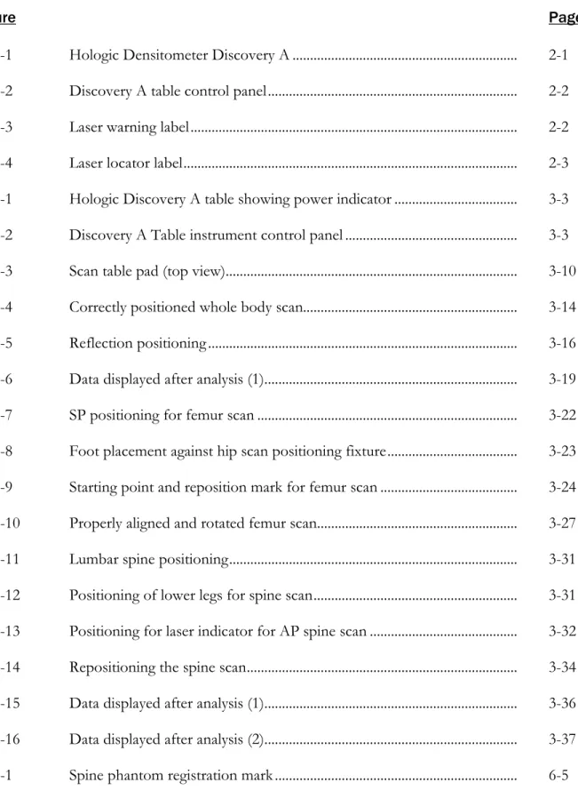
2-1 Hologic Densitometer Discovery A ... 2-1 2-2 Discovery A table control panel ... 2-2 2-3 Laser warning label ... 2-2 2-4 Laser locator label ... 2-3 3-1 Hologic Discovery A table showing power indicator ... 3-3 3-2 Discovery A Table instrument control panel ... 3-3 3-3 Scan table pad (top view) ... 3-10 3-4 Correctly positioned whole body scan... 3-14 3-5 Reflection positioning ... 3-16 3-6 Data displayed after analysis (1)... 3-19 3-7 SP positioning for femur scan ... 3-22 3-8 Foot placement against hip scan positioning fixture ... 3-23 3-9 Starting point and reposition mark for femur scan ... 3-24 3-10 Properly aligned and rotated femur scan... 3-27 3-11 Lumbar spine positioning ... 3-31 3-12 Positioning of lower legs for spine scan ... 3-31 3-13 Positioning for laser indicator for AP spine scan ... 3-32 3-14 Repositioning the spine scan ... 3-34 3-15 Data displayed after analysis (1)... 3-36 3-16 Data displayed after analysis (2)... 3-37
Contents (continued)
Figure Page
6-2 Spine phantom and laser crosshair position ... 6-5 6-3 Slim-Line whole body phantom fully assembled ... 6-19 6-4 Layout of whole body phantom—top view ... 6-29 6-5 Layout of whole body phantom—side view ... 6-30
Exhibit
3-1 Discovery QDR login screen ... 3-4 3-2 Discovery QDR screen with option of system backup ... 3-5 3-3 Discovery QDR screen main menu ... 3-6 3-4 Exiting the discovery QDR system ... 3-7 3-5 Selecting “perform exam” ... 3-11 3-6 Patient selection screen ... 3-12 3-7 Operator field for initials ... 3-12 3-8 Scan selection screen ... 3-13 3-9 Whole body scan parameters screen ... 3-16 3-10 Whole body scan image ... 3-18 3-11 Exit exam/new scan window box ... 3-18 3-12 Scan selection screen ... 3-20 3-13 Default Scan Mode unchecked ... 3-21 3-14 Left Hip Scan Mode Selection ... 3-21 3-15 Scan Parameters window for proximal femur scan ... 3-22
Contents (continued)
Exhibit Page
3-16 Hip scan window ... 3-25 3-17 Repositioning the femur ... 3-26 3-18 Scan selection screen ... 3-28 3-19 AP Lumbar Spine Scan Default Scan Mode unchecked ... 3-29 3-20 AP Lumbar Spine Scan Mode Options ... 3-29 3-21 AP Lumbar Spine Scan Parameters screen ... 3-30 3-22 Spine scan window ... 3-33 4-1 Shared exclusion questions ... 4-2 4-2 Exclusion from DXA due to pregnancy status ... 4-3 4-3 Shared exclusion questions without pregnancy question... 4-4 4-4 Exclusion from DXA due to data effect ... 4-5 4-5 Exam status “not done” due to data effect ... 4-5 4-6 Response options for question “where is the amputation?” ... 4-6 4-7 Weight/height entry screen ... 4-7 4-8 Weight/height information transferred from body measures ... 4-7 4-9 Entering the weight/height information into the screen ... 4-8 4-10 Selection for high-power scan ... 4-8 4-11 Screening questions ... 4-9 4-12 Screening question highlighted with options ... 4-10 4-13 Exclusion from spine scans ... 4-11
Contents (continued)
Exhibit Page
4-15 Scan right hip message ... 4-12 4-16 Scan left hip message ... 4-12 4-17 Whole body data capture (1) ... 4-13 4-18 Whole body data capture with reflection positioning ... 4-14 4-19 DXA data capture (2) ... 4-15 4-20 DXA data capture (comments on scan) ... 4-16 4-21 DXA data capture (scan not completed) ... 4-17 4-22 High-power (HP) message box ... 4-18 4-23 HP error message ... 4-18 4-24 DXA data capture (femur scan) ... 4-19 4-25 DXA data capture (femur scan) Femur Archive file name ... 4-20 4-26 DXA data capture (femur scan) ... 4-21 4-27 DXA data capture (AP spine scan) ... 4-22 4-28 DXA data capture (AP spine scan) AP Spine Archive file name ... 4-23 4-29 DXA data capture (AP spine scan) ... 4-24 4-30 DXA component status (required comments) ... 4-25 4-31 DXA component status ... 4-26 4-32 Session pickup list ... 4-28 4-33 Session preview report ... 4-29 4-34 Room log for body composition ... 4-30
Contents (continued)
Exhibit Page
5-1 Menu to select observation referral ... 5-1 5-2 Pick list of SPs in current session ... 5-2 5-3 Observation referral in body composition ... 5-2 5-4 Observation referral from other components in physician’s
referral review box ... 5-3 5-5 Sample report of findings for body composition ... 5-4 6-1 Discovery main menu ... 6-3 6-2 Daily QC setup box ... 6-4 6-3 System self-test ... 6-6 6-4 System test passed ... 6-6 6-5 Auto QC passed ... 6-7 6-6 Spine Phantom QC—plot for bone mineral density (BMD) ... 6-8 6-7 Spine phantom QC—plot for bone mineral content (BMC)... 6-9 6-8 Step phantom setup window ... 6-10 6-9 Step phantom scan ... 6-11 6-10 Step phantom evaluation completed successfully ... 6-12 6-11 Step phantom QC completed, press Continue ... 6-12 6-12 Selecting radiographic uniformity from patient list ... 6-13 6-13 Operator box for initials ... 6-14 6-14 Selecting whole body in the select scan type screen ... 6-14 6-15 Radiographic uniformity scan parameters screen ... 6-15
Contents (continued)
Exhibit Page
6-16 Radiographic uniformity test ... 6-16 6-17 Selecting radiographic uniformity for SD results ... 6-17 6-18 Low air global stats SD ... 6-17 6-19 High air global stats SD ... 6-18 6-20 Selecting slim-line WB phantom scan ... 6-20 6-21 Operator box for initials ... 6-21 6-22 Selecting whole body in the select scan type screen ... 6-21 6-23 Slim-line scan parameters screen ... 6-22 6-24 Selecting Hologic Femur/Hip Phantom from patient menu ... 6-23 6-25 Operator box for initials ... 6-24 6-26 Selecting Right Hip in the scan selection screen ... 6-24 6-27 Right Hip Scan Mode options ... 6-25 6-28 Hologic Femur/Hip Phantom Scan Parameters screen ... 6-25 6-29 Machine scanning Femur/Hip phantom ... 6-26 6-30 Exit exam/new scan window box ... 6-26 6-31 Quality control reminder message box ... 6-32 6-32 Utilities menu to select quality control ... 6-32 6-33 Quality control logon ... 6-33 6-34 Quality control daily checks ... 6-33 6-35 Quality control weekly checks ... 6-34 6-36 Quality control start of stand checks (1) ... 6-35
Contents (continued)
Exhibit Page
6-37 Quality control start of stand checks (2) ... 6-35 6-38 Quality control yearly checks ... 6-36 6-39 Quality control end of stand checks ... 6-37 6-40 Quality control incomplete entry ... 6-38
Overview of Body Composition 1
Body composition and bone health will be evaluated in the current National Health and Nutrition Examination Survey (NHANES) by anthropometry and dual energy X-ray absorptiometry (DXA).
These methods will be used to (1) monitor secular trends in overweight prevalence; (2) describe the prevalence of obesity; and (3) examine the relationship between overweight and obesity and other examination measures, including blood pressure, glucose intolerance, and a battery of indicators for cardiovascular disease.
1.1 Overview of Dual Energy X-Ray Absorptiometry
Dual energy x-ray absorptiometry (DXA) was included for the first time in the NHANES during NHANES III: 1988–94. Femoral bone mineral density was assessed at that time using pencil-beam bone densitometers (Hologic QDR 1000). In 1999–2006 and 2011–16, the DXA component included acquisition of whole body DXA scans using Hologic QDR 4500A fan-beam bone densitometers. Scans of the proximal femur and anterioposterior (AP) or lumbar spine were collected in 2005–10 and 2013–14.
The NHANES whole body DXA data will be used to examine age, sex, and racial/ethnic differences in body composition (bone mineral, lean soft tissue, and fat mass) during the life cycle to explore the relationship between body composition and behavioral factors such as diet and physical activity and physiologic factors such as hypertension, diabetes, cardiovascular disease, and muscle strength. All individuals 8–59 years are eligible for the whole body scan, with the exception of pregnant females.
The femur and AP lumbar spine scans will provide information on osteoporosis and low bone mass for participants ages 50 years and older.
The DXA Whole Body scan will be completed on all individuals 8 through 59 years (see Table 1-1).
The femur and AP spine will be completed on sample persons (SPs) 50 years and older. Pregnancy status will be assessed on all females 12 through 59 years and menstruating 8- to 11-year-olds. If the result of the pregnancy test is positive, the SP will be excluded from the entire exam. If a pregnancy test for an SP who is 8–17 years old comes back positive, a second test will be done for
Overview of Body Composition
1
confirmation. In addition, women aged 12 through 59 years will be asked to self-report their pregnancy status and will be excluded if they respond “Yes” or “Don’t Know,” even if the
pregnancy test was negative. Self-report on pregnancy status for 12- to 15-year-old females will be asked in the Physician’s Exam. Females 8 through 11 years of age will not be asked about pregnancy status (see Table 1-2).
Table 1-1. Age groups and gender for body composition
Component Age Gender
DXA (whole body) 8–59 Males and females
DXA femur 50 + Males and females
DXA AP spine 50 + Males and females
Table 1-2. Pregnancy status information for body composition by age and gender
Pregnancy status Age Gender
Pregnancy status—urine test 12–59 years Females
Pregnancy status—urine test Menstruating 8-11 years Females
Pregnancy status—self report 12–59 years Females
Pregnancy status—self report (Asked in Physician’s Exam) 12–15 years Females Pregnancy status—self report (Shared Exclusion Question) 18–59 years Females
1.2 Risks
The risk from DXA scans is low. The average effective dose to an individual in the United States from background radiation is approximately 3600 microsieverts (μSv) per year. A standard diagnostic x-ray of the spine, for example, delivers an effective radiation dose of 1100 µSv.
The total estimated effective radiation dosage in µSv by age:
8–59 years: 4.2 to 5.2 for whole body scans;
50–59 years: 15.6 for whole body, femur, and AP lumbar spine; and
60+ years: 11.4 for femur and AP lumbar spine.
Overview of Body Composition
1
1.3 Personnel
A certified radiology technologist will conduct all DXA scans.
1.4 Flow of Body Composition
The body composition exam will begin with the whole body DXA scan, followed by the femur scan, and the AP spine scan. Participants will receive one or more scans, with a maximum of three DXA scans. Under no circumstances should a whole body scan be repeated. If a problem occurs during any of the scans, it should be documented in the Integrated Survey Information System (ISIS) Data Capture screen and/or an Unusual Field Occurrence (UFO) if necessary.
Equipment/Supplies/Materials 2
2.1 Description of Equipment for DXA 2.1.1 Hologic Discovery A
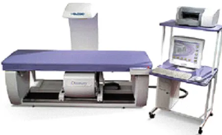
The Hologic Discovery A (Figure 2-1) is a fan beam x-ray bone densitometer, which uses two different energy levels produced by an energy tube to estimate bone mineral content (BMC) and bone mineral density (BMD). The Discovery A uses a low level of x-rays, and under standard operating conditions, the entrance dose to the examinee for a whole body scan is less than 1 mR1 (a standard x-ray is approximately 35 mR).
Figure 2-1. Hologic Densitometer Discovery A
The densitometer produces ionizing radiation in the form of x-rays and uses laser radiation to position scans, although the radiation exposure is so low that no shielding of the room or of health technologists is required.
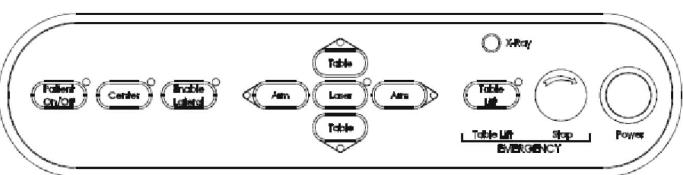
The x-ray ON indicator is an amber light located in the upper right corner of the instrument control panel (see Figure 2-2). When the x-ray lamp is lit, x-rays are being produced.
Equipment/Supplies/Materials
2
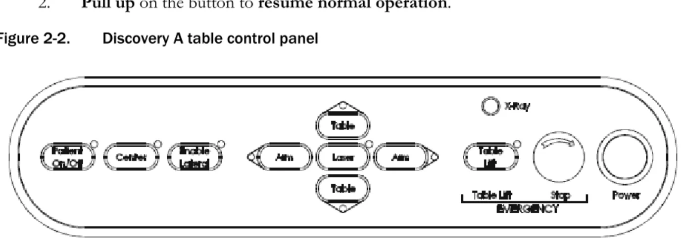
The Emergency Stop Button is a round red button at the right end of the Discovery A table control panel that is used for emergencies. When this button is pressed, the X-rays and the table are disabled and scanning stops immediately. Pulling on the button resumes normal operation.
1. Press down on the button to stop the scan.
2. Pull up on the button to resume normal operation. Figure 2-2. Discovery A table control panel
Laser positioning. The Laser-On Lamp is an amber light above the laser switch on the Discovery A table control panel. It alerts the user that the laser position indicator is active. The laser position indicator unit produces 1 mW laser emission. The examinee and technologist should avoid looking directly into the beam or placing reflective objects in the path of the beam.
The Discovery A table includes a laser safety feature that turns the laser off if the distance between the top (right side) of the table is less than approximately 15.5 inches from the laser light spot. This feature is there to help prevent shining the laser light in the examinee’s eyes. Figure 2-3 shows the laser warning label located on the scanner arm.
Figure 2-3. Laser warning label
Equipment/Supplies/Materials
2
Arrows marked “Laser Aperture” mounted on the scanner arm note the location of the laser beam.
Figure 2-4 shows the laser locator label.
Figure 2-4. Laser locator label
2.1.2 Discovery QDR System Operations
See Section 3.3 in Chapter 3 for Startup and Shutdown Procedures for the Discovery QDR System.
See Appendix I for Power Failure Procedures.
2.1.3 Supplies
Disposable exam paper is used for all sample persons (SPs). A clean layer of the paper is placed on the exam table between each SP.
A Velcro strap is used to prevent movement of the feet during the whole body scan.
This is tied around the SP’s ankles with his or her toes pointing up.
A radiolucent contour pillow can be used to support the head for SPs who have trouble lying flat due to back problems or difficulty breathing.
Foam wedges can also be used to support the head, or they may be placed under the knees for SPs having difficulty lying flat.
Foam sponges may be used to separate the hands from the torso during the whole body scan, or between the feet to prevent any overlapping.
A plexiglass ankle positioning tool is used to assist in positioning the leg for the femur scan.
A large cube positioning tool is used to assist in positioning for the spine scan.
Equipment/Supplies/Materials
2
2.1.4 Radiation Badges
Health technologists operating the densitometers are required to wear radiation badges for densitometry processing. A badge specific for each mobile examination center (MEC) is placed in the room on the computer cart beside the densitometer. A control badge for each team is kept in a radiation free-area on the MEC, such as the staff lounge. This control badge travels with the team to each stand.
2.2 Maintenance and Repair of Equipment for DXA
If the component lead health technologist (CLHT) needs to contact Hologic for repair, notify the MEC manager and the home office of the problem. Be sure to document the call in the Hologic Call Log. The Hologic contact number and other important information are listed below:
Call Hologic customer support at 1-800-321-4659.
Provide the model number and the serial number for your machine.
–
Model number for all MECs is Discovery A.–
Serial number for MEC 1 = 85257.–
Serial number for MEC 2 = 85286.–
Serial number for MEC 3 = 85148. Provide the location of the MEC at the time the service will be needed.
–
Confirm with the Hologic person making the reservation and with the Hologic Service Technician the location of the MEC. They often confuse this with the last place the MEC was when it was serviced.Equipment/Supplies/Materials
2
2.2.1 Maintenance and Repair Reports
When the Hologic densitometer is serviced or repaired, it is the responsibility of the CLHT to confirm that all required reports are completed, stored, and sent to the appropriate people. These reports include the following:
2.2.1.1 Regular Reports:
1. Field Service Report (FSR):
When the Hologic densitometer is serviced or repaired:
The Hologic service technician will complete an FSR and will send the FSR to the Facilities and Equipment Specialist (FES) or CLHT.
The FES will email the FSR to the home office project person and copy the CLHT and MEC Manager.
The CLHT will confirm that the FSR was sent to the home office project person and put a copy of the FSR in the service report binder kept in the DXA room.
2. DXA Bone Densitometer Report (BDR):
When the Hologic densitometer is serviced or repaired, the CLHT will do the following:
Complete a “DXA Bone Densitometer Report (BDR)”;
Scan and send an electronic copy of the DXA BDR to the home office, which will send this report to NCHS and the Quality Control Reading Laboratory; and
Place a copy of the DXA BDR in the service report binder kept in the DXA room.
Blank DXA BDR forms are stored electronically in the Integrated Survey Information System (ISIS) system. Open Word, select File/Open, and look in the directory for Mecstaff/Blank
forms/DXA_serv.doc.
3. Hologic Customer Service Log (Call Log):
When the Hologic densitometer is serviced or repaired, the CLHT will do the following:
Enter the date, description of the problem, the solution, and the CHLT’s initials for
Equipment/Supplies/Materials
2
At the end of the stand, scan and send an electronic copy of the Call Log to the home office, which will send it to NCHS and the Quality Control Reading Laboratory.
2.2.1.2 Preventative Maintenance Reports:
Preventative Maintenance (PM) will be completed on each of the densitometers twice a year.
The first Preventative Maintenance of the year will be completed prior to the first stand of the year for each of the mobile examination center (MECs) (January/February). This will require coordination between the FES and CLHT on the MEC where the Preventative Maintenance is to be completed. Because this Preventative Maintenance will be completed prior to the setup at that stand, this means the CLHT will be scheduling a Preventative Maintenance for a location where the survey will be going next. The CLHT will have to get the information for that MEC. It is the
responsibility of the CLHT to follow up with the FES and Hologic service technician to confirm that the PM is scheduled and completed prior to setup. See Section 2.2 for the information needed to contact Hologic for the Preventative Maintenance.
The second Preventative Maintenance of the year will be completed approximately 6 months following the previous one (July/August). The Preventative Maintenance will be scheduled prior to setup and will also require coordination between the FES and CLHT on the MEC where it is to be completed. The coordination, responsibility, and followup are the same as for the first Preventative Maintenance.
The reports associated with Preventative Maintenance include the following:
1. Field Service Report (FSR):
The FSR for the Preventative Maintenance is the same form used for regular service. Note that if you have to schedule a service for another problem with the machine, the Hologic service technician will complete two separate FSRs, one for the Preventative Maintenance and one for the issue with the machine or software.
2. Preventative Maintenance Checklist (PMC):
When the Preventative Maintenance service is completed by the Hologic service technician:
The Hologic service technician will complete the PMC and email it to the FES;
Equipment/Supplies/Materials
2
The FES will email the PMC to the home office project person and copy the CLHT and MEC Manager; and
The CLHT will confirm that the PMC was sent to the home office project person and put a copy of the PMC in the service report binder kept in the DXA room.
3. Radiation Measurement Report (RMR):
When the Preventative Maintenance service is completed by the Hologic service technician:
The Hologic service technician will complete the RMR and email it to the FES;
The FES will email the RMR to the home office project person and copy the CLHT and MEC Manager; and
The CLHT will confirm that the RMR was sent to the home office project person and put a copy of the RMR in the service report binder kept in the DXA room.
2.3 Calibration of Equipment for DXA
Refer to Chapter 6 for complete instructions regarding calibration and quality control scanning procedures.
Protocol 3
3.1 Introduction to the DXA Examination
The technologist should briefly explain the examination when the sample person (SP) is brought into the room. The exam should be explained in more detail as it is being conducted. The objective is to inform the SP about the exam and to position the SP as quickly as possible. Below is a
suggested introductory script, but the examiner should use his or her own words for this explanation. This is an explanation, not a standard script, so the technologist may adjust the explanation to the level of understanding of the examinee.
Suggested introduction to component (English version):
“In this room, we are going to be doing one or more scans of your body that will tell us how strong your bones are and how much body fat you have. I will explain in more detail as I do the exam. Please have a seat up here on the table and get as comfortable as possible. I am going to ask you a few questions before I start the exam.”
3.2 Explanation of the DXA Examination
The technologist is scanning the ID wristband of the examinee during the explanation of the exam.
The explanation should be used as a guideline only and the technologist should adjust the explanation to the level of understanding of the SP. The script used for an 8-year-old will be
different from the script used for a 59-year-old. The scripts below provide suggested explanations of the body composition and the DXA exams.
Suggested explanation of whole body DXA scan (English version):
“For this examination, I will be doing a scan of your body with this machine. It will tell us how much body fat you have. Now please lie down on the table and I will position you for the scan. I’m going to pull up on your shoulders to straighten you. I will position your arms and feet correctly for the scan and then wrap these Velcro straps loosely around your ankles to hold them in place. The scan will take about 3 minutes to complete and you will not feel anything except for the table movement. As the machine scans your body, the table will move up and down and back and forth. This overhead arm (the C-arm) will also be moving. In order to
Protocol
3
receive a good quality scan, it is important that you lie perfectly still during the scan and do not talk.”
Suggested explanation of femur scan (English version):
“This scan will be of your hip; it will tell us how strong your bones are. For this scan, please continue to lie still with your legs flat against the table. I will rotate your left leg inward slightly and then keep it in place using this foot brace. Please place your arms across your chest. You will not feel anything during the scan. Please be as still as possible and do not talk during the scan.”
Suggested explanation of AP lumbar spine scan (English version):
“These spine scans will also tell us how strong your bones are. For these spine scans, you will lie flat on the table. I’m going to place a pillow under your head. Then I am going to bend your legs at a 90º angle at the hip and knee by placing them on this large, soft, cube-shaped pillow. You will not feel anything during this scan. Please be as still as possible and do not talk during the scan. For the last two scans I will need you to place your arms over your head and hold your breath for 10 seconds.”
Suggested explanation after completion of scans (English version):
“Please stay lying down until I have moved the overheard arm out of the way. Now you can sit up. You will receive the results in the mail in 12-16 weeks. Let’s find out where you go next.”
3.3 Discovery A Table and Discovery QDR System Operation
The Discovery QDR system should be turned on at the beginning of the day and off at the end of each session for that day. See Appendix C for setting up the Discovery A table for operations.
Routine Discovery QDR system startup procedures for the beginning of a session are outlined below in Section 3.3.1. See Appendix H for securing the Discovery A table for travel. Routine shutdown procedures are outlined in Section 3.3.2. See Appendix I for power failure procedures for DXA.
3.3.1 Startup Procedures for Hologic Discovery A Table (Start of Session)
Confirm these settings first.
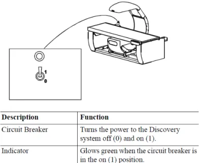
Verify that the green indicator on the back of the left pedestal is on. (This light indicates
Protocol
3
power failure occurs. See Figure 3-1 below. If the green light is not on, check and see if the UPS (uninterruptible power supply) is plugged into the outlet; if not, plug it in and then make sure the circuit breaker switch is in the on (1) position. If the green indicator does not light up, notify the Facilities and Equipment Specialist (FES).
On the control panel, the POWER green indicator light should be on. If not, press the POWER button to turn it on. See Figure 3-2.
The Hologic COMPUTER POWER switch located underneath the workstation should be ON. (This is left ON to allow network backup overnight.)
Figure 3-1. Hologic Discovery A table showing power indicator
Figure 3-2. Discovery A Table instrument control panel
Protocol
3
Turning the Hologic Discovery QDR System ON (Start of Session Routine Procedure):
When the Discovery QDR system login screen is displayed, double-click on QDR (soccer ball icon). See Exhibit 3-1. If the QDR database has not been backed up, a dialog Windows box will appear: “A backup of your QDR system’s database has not been performed in # days! Do you want to perform a system backup now?” Click
“No.” See Exhibit 3-2.
The X-ray table will turn on and the Discovery QDR Main Menu will be displayed (see Exhibit 3-3).
Log in to the Integrated Survey Information System (ISIS). A message will be displayed:
“Drive P successfully mapped.” Exit and do not save this file.
NOTE: DO NOT log on to ISIS until the startup for the Hologic computer has been completed. If the ISIS computer is opened before the Hologic computer, a message will be displayed after the scan is completed: “Unable to find drive specified.” If you get this message, call the ISIS Help Line.
Open the DXA/Body Composition application on the ISIS screen.
Exhibit 3-1. Discovery QDR login screen
Protocol
3
Exhibit 3-2. Discovery QDR screen with option of system backup
3.3.2 End of Session Shutdown Procedures for Discovery QDR System
Close the DXA/Body Composition application. The screen should display the Discovery QDR Main Menu. (See Exhibit 3-3.)
Protocol
3
Exhibit 3-3. Discovery QDR screen main menu
3.3.3 End of Day Shutdown Procedures for Discovery QDR System
Click Exit (bottom right corner). Then select “Exit QDR without Shutdown” and click OK. See Exhibit 3-4. Leave the monitor at blue screen. The Hologic computer should always be kept on through the duration of the stand.
Reboot ISIS.
Protocol
3
Exhibit 3-4. Exiting the discovery QDR system
3.4 Examinee Preparation for the DXA Examination
The sample person (SP) should be logged into ISIS as soon as possible after he or she has entered the room.
3.4.1 Measurement of Weight and Height to Determine Body Mass Index
After answering the Shared Exclusion Questions, the next screen displayed will be the weight/height data entry screen. See Exhibit 4-8 in Chapter 4. If the SP was in the anthropometry (body measures) component prior to this test, the weight and height will already be uploaded and displayed on the ISIS screen, along with the component it transferred from (e.g., body measures). See Exhibit 4-9 in Chapter 4. If the information is not displayed, you will need to measure the SP’s weight and height using the floor scale and stadiometer in the room. The system will use the weight and height measurements to calculate the body mass index, which will determine whether the SP needs the high-power whole body scan or not. The same precision to take the weight and height
measurements in the anthropometry component must be used in this component.
Protocol
3
3.4.1.1 Weight
Follow these steps to take the SP’s weight:
1. Make sure the scale weight is in kilograms by checking the switch on the underside of the digital display.
2. Place the scale on the floor.
3. Switch on the scale by gently pressing the blue ON button. Have the SP remove his or her shoes and any outer clothing such as sweaters, jackets, etc.
4. Wait until the display 0.0 kg and the Ready/Complete symbol O appear on the digital display. Have the SP step on the scale with his or her feet positioned in the center.
5. Ask the SP to stand straight and remain still.
6. The scale will display “----” while it is taking the SP’s measurement. Record the weight in kilograms in the weight field.
7. Ask the SP to step off the scale. The scale switches off automatically after 45 seconds of inactivity.
If the SP’s weight is more than 450 pounds, he or she will be excluded from the entire body composition component due to the weight limitation of the table. If the SP is greater than 450 pounds after weighing, the application will still ask you to obtain the height. After you enter the height, the SP will be excluded from the exam, and the exam status will be set to “Not Done” due to
“weight limitation on equipment.”
3.4.1.2 Height
Follow these steps to take the SP’s height:
1. Ask the SP to remove his or her shoes if necessary.
2. Place the stadiometer a few inches away from the wall. Check to be sure the
measurement column on the stadiometer is completely inserted into the floor piece. Pull the sliding top bar section up and open the head piece to allow the SP to step under the head piece.
3. Ask the SP to stand erect on the floorboard with his or her back to the vertical piece of
Protocol
3
4. Ask the SP to evenly distribute weight on both feet. The heels are placed together with the feet pointed slightly outward at a 60º angle. The arms hang freely, by the sides of the trunk, with palms facing the thighs.
5. Position the head in the Frankfort horizontal plane. The head is in the Frankfort plane when the horizontal line from the ear canal to the lower border of the orbit of the eye is parallel to the floor and perpendicular to the vertical backboard. Many people will assume this position naturally, but for some it may be necessary to make a minor adjustment. If required, gently tilt the head up or down until proper alignment is
achieved with the eyes looking straight ahead. Lower the headpiece snugly to the crown of the head with sufficient pressure to compress the hair. Once correctly positioned, ask the SP to inhale deeply and to stand fully erect without altering the position of the heels.
6. Hold the top sliding bar in place at the junction and ask the SP to step out away from the stadiometer.
7. Record the measurement in centimeters (measurements printed on right side of bar) at the orange line on the measuring bar.
If the SP is greater than 6’5”, he or she will be excluded from the whole body scan due to limitations of the table. The exam status will be set to “Not Done” with the comment “Exceeds height
limitation.”
3.4.1.3 Body Mass Index
After entering the SP’s weight and height, the ISIS application will calculate the body mass index (BMI) for the SP. If the SP is a male with a BMI > 31, or a female with a BMI > 32, they will be selected for the high power option. A pop-up message will come up stating, “This SP has been selected for the HP Whole Body Scan.” Be sure to select this scan under the scan type in the Hologic Discovery QDR system. The high-power whole body scan will be performed only on SPs 18 years or older.
3.4.2 Preparing the SP
The next screen will have the screening and safety exclusion questions. Go through the questions with the SP, and then have him or her remove all metal objects from his or her body (jewelry, belts, snaps, underwire bras). If the SP has small objects such as rings that will not come off, mark “No”
in the screening questions and proceed with the exam. (Inability or refusal to remove jewelry is not
Protocol
3
exclusion for DXA; however, the SP should be encouraged to remove all metal objects if possible.) False teeth and hearing aids do not have to be removed. If a female SP needs to remove her bra for the scan, pause the exam and escort her to the nearest restroom at this time.
Before moving the table or C-arm:
Confirm that the runner area of the table is clear of objects that might interfere with table movement; and
Check that the table scan area is clear of articles that might interfere with table movement.
Press the left arm switch on the Discovery A table Control Panel to allow the C-arm to move to the far left and extend the table out from the base. See Figure 3-2 earlier in this chapter. This will make it easier for the SP to get on (or off) the table.
After the C-arm and table stop moving, have the SP lie down on his or her back with his or her head to your right as you face the table. Press the “Center” switch on the Control Panel, and wait for the C-arm to position itself to the center of the table.
Make sure that the SP’s body is entirely within the scan limit borders on the pad, especially the SP’s head (see Figure 3-3.)
Figure 3-3. Scan table pad (top view)
Protocol
3
3.5 Whole Body DXA Scan
Make sure all Shared Exclusion, Screening, and Safety Exclusion Questions in ISIS have been answered and you are up to the Data Capture screen in ISIS before performing a scan. In the Hologic computer click the “Perform Exam” icon or “Exam” in the top menu bar and select
“Perform Exam” from its drop-down menu (Exhibit 3-5).
Exhibit 3-5. Selecting “perform exam”
3.5.1 Selecting an SP
In the “Patient Selections” screen, enter the SP ID from the ISIS screen into the blank white field for Patient Name, or highlight the SP ID from the list of IDs under the Patient Name column.
Double-check that you entered the correct SP ID by asking the SP for his or her date of birth. Press “OK.” See Exhibit 3-6.
Protocol
3
Exhibit 3-6. Patient selection screen
Enter your initials in the “Operator” field and click OK. See Exhibit 3-7.
Exhibit 3-7. Operator field for initials
3.5.2 Selecting the Type of Scan
The next screen will display the types of scans to choose from. In the “scan selection” screen, select the scan type by clicking on “Whole Body” with the mouse. The scan type is highlighted. See
Protocol
3
Exhibit 3-8. Click the “Next >>“ button.Note that if the SP was selected for the high-power whole body option, select HP Whole Body from the scan selection screen.
Exhibit 3-8. Scan selection screen
The Whole Body Scan Parameters screen will display. See Exhibit 3-9 later in this chapter.
Verify the SP ID under Patient Name and the scan type in the upper left corner. Stop here and position the SP for the scan.
3.5.3 Positioning the SP
Check to make sure the SP is in the center of the table with respect to the center lines at the head and foot of the pad. One method to check this is to position yourself at the foot of the table and look at the alignment of the body. Visualize a straight line from the nose, center of the body, and down through the knees and toes.
Leave at least two finger spaces between the top border line and the SP’s head to avoid clipping the head in the scan.
During the head positioning the chin should be straight to avoid the neckline being cut through the shoulder bone.
The SP should lie flat on the table without a pillow. If the SP has trouble lying flat due to back problems or difficulty breathing, use the radiolucent pillow to support the head.
The pillow should be covered with the disposable exam paper. If the pillow does not provide sufficient support, use the radiolucent foam block or one of the foam wedges.
These may also be used under the knees if the SP has difficulty lying flat.
Protocol
3
If the SP continues to have difficulty lying flat or with the head slightly supported, exclude him or her from the exam.
Gather the disposable scrub top on top of the belly area for proper hip positioning and tuck the disposable bottom under the hip area for leg positioning.
The legs must be positioned together with the feet relaxed and toes pointed upwards.
Use the Velcro strap around the ankles to support the legs in this position and to prevent any movement. Do not wrap the Velcro strap too tightly and make sure there is at least half an inch to an inch space between the feet. See Figure 3-4 for proper
positioning of the whole body scan.
Place the SP’s arms straight at his or her sides, palms down, with separation from the torso. Verify that the arms are within the scan border. If necessary, with larger SPs the hands may be placed in a lateral position next to the hips to remain within 1” of the scan border. Do not tuck the hands under the body.
There must be a space between the SP’s arms and sides whenever possible.
Remind the SP to breathe normally during the scan and pay attention to the SP while the C-arm is moving. Coach the SP through the scan; for example: “That was the first pass,” “You are doing well,” or “We’re almost done.”
Figure 3-4. Correctly positioned whole body scan
Protocol
3
3.5.4 Reflection Positioning
There are several challenges in the scanning and analysis of heavy SPs. Reflection positioning should be used when an SP does not fit within the scan border. A “Reflection” protocol is where the patient is positioned off the center line of the scan table to ensure that one side, typically the right side, is completely included in the scan field. On the resulting image, the pelvis must be totally included. All SPs ages 18-59 who require reflection positioning should receive a high-power whole body scan if not already identified by their BMI values.
Positioning:
Position the subject the same as for a normally centered scan.
Offset the SP to his or her left so the right side is included in the scan area; try to keep the torso within the scan area.
The right side of the body and the left pelvis area should be at least one inch from the scan border. The entire pelvis including the bones and soft tissue must be within the scan border.
Make sure the spine is straight (parallel to the center lines).
There should still be separation of the hands and arms with the body.
With the offsetting, the left arm has to be out of the scan area up to and including the elbow for the “Reflection” technique to activate. See Figure 3-5. The right hand should be flat on the table or lateral to the table to allow for separation between the hand and arm and the body (you may have to feel for the separation with some SPs).
Place the cover over the control panel to prevent the emergency button from getting pushed.
Scan the SP as usual.
Be sure to mark Reflection positioning under the scan comments.
Protocol
3
Figure 3-5. Reflection positioning
Exhibit 3-9. Whole body scan parameters screen
After the SP is positioned correctly for the whole body scan, check one more time to ensure there are no objects that will interfere with the movement of the table or the runner belt. Press “Start Scan” to begin the scan.
The machine will complete the scan.
Protocol
3
Warning: If the Control Panel X-ray indicator fails to shut off within 10 seconds after the end of the scan, press the red Emergency Stop button immediately. Call the Hologic service representative before resuming operation.
Positioning (Last Resort):
If an SP is very large and the technician is not able to image both sides of the torso on reflection, use the “last resort” procedure to attempt to obtain as much data as possible.
Position the SP in the center of the table with both hands at his or her sides (same as for a normally centered scan under Section 3.5.3).
Check to ensure there are no objects (including SP’s hands) that will interfere with the movement of the table or the runner belt. In this case, the main focus is the trunk and not including hands and arms is acceptable.
Press “Start Scan” to begin the scan.
Make sure to document this under the scan comments to be communicated with QC Reading Center.
3.5.5 Completing the Scan
The Scan window displays with the image appearing on the left side. The flashing “X-rays On”
indicator at the top of the window continues until the scan stops. See Exhibit 3-10.
Make sure the SP’s arms are included in the scan on the first and last pass of the C-arm. The SP should remain still until the scan is complete. Allow the scan to complete.
Protocol
3
Exhibit 3-10. Whole body scan image
The analysis will be done later by the QC Reading Center.
Go to the ISIS screen and complete the DXA Data Entry screen.
Remove the Velcro strap from the SP’s ankle and clean it with a Sani-wipe.
See Chapter 5 for a description of the information provided to the SPs from this test.
When the exam completes, an Exit/New Scan window box displays. See Exhibit 3-11.
Click on “Exit Exam.”
Exhibit 3-11. Exit exam/new scan window box
Protocol
3
3.5.6 DXA Scan Data
Analysis of the scans will be done at the QC Reading Center.
Figure 3-6 shows the data displayed after the regions of interest are selected and the analysis is completed.
This figure also displays the percent fat by region and for the total body. The percent total body fat for the hypothetical SP in the example is 23.6 percent.
Figure 3-6. Data displayed after analysis (1)
Protocol
3
3.6 Proximal Femur Scan 3.6.1 Selecting the SP
If this is the first scan for the SP, click the “Perform Exam” icon or “Exam” in the top menu bar and select “Perform Exam” from its drop-down menu. See Exhibit 3-5 earlier in this chapter.
If the Whole Body scan has already been performed, click “New Scan” from the Exit/New Scan window (see Exhibit 3-11) earlier in this chapter.
3.6.2 Selecting the Type of Scan
At the “scan selection” screen (Exhibit 3-12), choose left hip, unless answers to safety exclusion questions warrant using the right hip.
Exhibit 3-12. Scan selection screen
Protocol
3
Click to uncheck the “Use Default Scan Mode” (Exhibit 3-13) and click “Next >>.”
Exhibit 3-13. Default Scan Mode unchecked
In the Left Hip Scan Mode window (Exhibit 3-14) select “Fast Array (f)” and click “Next >>.”
Exhibit 3-14. Left Hip Scan Mode Selection
The Scan Parameters window appears (see Exhibit 3-15). Verify the SP ID and scan type in the upper left corner.
Protocol
3
Exhibit 3-15. Scan Parameters window for proximal femur scan
3.6.3 Positioning the SP
The SP should be positioned with his or her head to your right as you face the table. Make sure that the SP is straight and centered on the table. The hip region should be within the two sets of hash marks on either side of the long edge of the table (see Figure 3-7).
Figure 3-7. SP positioning for femur scan
Protocol
3
On the control panel, press the Center Table switch to move the table and C-arm to the center position.
Place the foot positioner under the SP’s legs, and align the center of the positioner with the patient’s midline. The leg to be examined should be rotated inward so that the foot can be placed against the foot positioner and secured with the Velcro strap (Figure 3-8).
A soft rubber ball can be used between the heel of the foot and the foot positioner.
The foot should be flexed toward the ceiling. Adjust the abduction of the leg so that the shaft of the femur is straight and parallel with the center of the table.
NOTE: In rotating the leg inward, place one hand above the knee and one hand below the knee and gently rotate the leg to ensure the whole leg is rotated, as opposed to just the lower portion of the leg. Another option is to pick up the leg, bend it outward at the knee, then rotate the leg inward, sliding the foot down the foot positioning device. Do not rotate more than is needed to minimize the lesser trochanter.
Make sure that the SP’s arms are placed across his or her chest outside of the scanning area to prevent the SP from placing his or her thumb or fingers under the hip.
Figure 3-8. Foot placement against hip scan positioning fixture
3.6.4 Positioning the C-Arm and Aligning the Laser
Locate the SP’s greater trochanter. This can be done as described below:
Grasp the leg to be scanned near the ankle and gently rotate the leg inward and outward several times. Press firmly on the outside of the thigh while rotating the leg. You should feel the greater trochanter roll under your fingertips.
Protocol
3
If you are not able to feel the trochanter, have the SP bend the leg at the knee and lift (may be necessary to assist the SP). Locate the crease formed at the top of the leg and use this as an approximate location of the greater trochanter.
In both cases, these are approximate location(s) to begin the scan.
Move the C-arm until the laser crosshair is 2 inches below the level of the greater trochanter and is on the center shaft of the femur (Figure 3-9). See “Starting Point Left”
and “Starting Point Right.”
Align the femoral shaft so it is parallel to the horizontal line of the laser.
Figure 3-9. Starting point and reposition mark for femur scan
Protocol
3
3.6.5 Scanning
Reconfirm that the SP is properly positioned and press “Start Scan” to begin the scan. The Scan window displays with the image appearing on the left side. The flashing “X-rays On” indicator at the top of the window continues until the scan stops. The image will appear on the screen, one line at a time from the bottom up (Exhibit 3-16).
Exhibit 3-16. Hip scan window
Inspect the image as it is generated. If the hip is positioned correctly, allow the scan to complete. If the hip is not positioned correctly, click the “Reposition Scan” button to stop the scan when the outer edge of the greater trochanter can be identified. If needed, straighten the femur shaft when scanning and continue the scan until the flexion between the head of the femur and the neck of the femur can be seen. Then reposition the image to the correct centering point and obtain the scan.
NOTE: An acceptable hip scan includes the following:
The femoral shaft is straight and parallel to the edge of the scan image.
The scan includes the entire femoral head, neck, and approximately 3 inches of the shaft.
The greater trochanter is centered vertically in the window.
Protocol
3
A 25º internal hip rotation of the hip showing minimal or no lesser trochanter on the scan image.
NOTE: If the scout scan reveals that the SP has a hip replacement or pin previously not reported, stop the scan and proceed with scan on the other hip, if possible. If this is not possible, discontinue the scan and complete the Femur Scan data entry scan to document the reason for the incomplete scan.
Reposition the image up, down, left, or right using the scroll bars or cursor hand to include the entire femoral head, neck, and approximately 3 inches of the shaft (see Exhibit 3-17, Repositioning the femur). If the femoral shaft is not parallel with the edge of the scan, move the SP’s leg away from or toward the midline.
The new starting point is automatically adjusted to have the correct amount of soft tissue lateral to the greater trochanter.
Exhibit 3-17. Repositioning the femur
Press “Restart Scan” to return to the scan parameter screen.
When the Scan Parameter screen re-appears, press “Start Scan” to repeat the scanning process.
Protocol
3
The scanning will start from the corrected starting point. Repeat the re-scan process one more time if necessary. The scan should only be repositioned a maximum of 2 times...
See Figure 3-10 for an example of a properly aligned and rotated femur scan.
Figure 3-10. Properly aligned and rotated femur scan
Lesser trochanter is barely visible
Shaft of femur is straight
The analysis will be done later by the QC Reading Lab.
Go to the ISIS screen and complete the Femur Scan screen. Be sure to inspect the scan thoroughly to include any comments that may be necessary.
Remove the SP’s leg from the hip positioning device.
3.6.6 Panniculus (Belly Fat Pad)
On very obese SPs, the fat pad of the belly can overlie the head of the femur, changing the bone mineral density (BMD) value. This is a major source of error that will cause the analysis of the scan to be inaccurate.
When presented with an obese SP, gently palpate the area to determine if there will be obesity noise.
Ask the SP to hold the fat pad out of the way with his or her hands by pulling it up and away from the femoral area. If unsure from palpation, start the scan, and if obesity noise is present, repeat the scan with the panniculus retracted.
Document this on the DXA Proximal Femur Data Capture Screen in the “Other” text box under
“Comment on scan” by typing, for example, “Belly fat pad retracted.”
Protocol
3
3.7 AP Lumbar Spine Scan 3.7.1 Selecting the SP
If this is the first scan for the SP, click the “Perform Exam” icon or “Exam” in the top menu bar and select “Perform Exam” from its drop-down menu. See Exhibit 3-5 earlier in this chapter.
If the femur scan has already been performed, click “New Scan” from the Exit/New Exam windows box. See Exhibit 3-11 earlier in this chapter.
3.7.2 Selecting the Type of Scan
In the “scan selection” screen select the scan type by clicking on “AP Lumbar Spine” with the mouse. The scan type is highlighted. See Exhibit 3-18.
Exhibit 3-18. Scan selection screen
Uncheck the “Use Default Scan Mode” (Exhibit 3-19) and click “Next >>.”
Protocol
3
Exhibit 3-19. AP Lumbar Spine Scan Default Scan Mode unchecked
In the AP Lumbar Spine Scan Mode window (Exhibit 3-20) select “Fast Array (f)” and click “Next
>>.”
Exhibit 3-20. AP Lumbar Spine Scan Mode Options
The AP Lumbar Spine Scan Parameters screen will display. See Exhibit 3-21. Verify the SP’s name and scan type in the upper left corner.
Protocol
3
Stop here and position the SP and the C-arm.
Exhibit 3-21. AP Lumbar Spine Scan Parameters screen
3.7.3 Positioning the SP
The SP should be positioned with his or her head to your right as you face the table. Make sure that the SP is straight and centered on the table and that his or her shoulders are 3-4 inches below the upper scan limit hash marks on the long edges of the table. See Figure 3-11.
NOTE: It may be helpful to stand at the head end of the DXA table, reach under the SP’s underarms, and gently pull toward you to straighten the spine.
On the control panel, press the center table switch to move the table and C-arm to the center position.
Place the large cubed cushion under the SP’s lower legs with the thighs as close to a 90- degree angle to the body as possible. Use the proper dimension of the cushion since the longest dimension could lift the SP’s buttocks off the table, causing the SP to rotate. It
Protocol
3
is important to have the SP stable and positioned. (See Figure 3-12.) Have the SP rest his or her arms comfortably at his or her sides.
Scoliotic SPs should be positioned using the same guidelines. The spine should be centered in the scan field and straight as much as possible without causing undue discomfort to the SP.
Figure 3-11. Lumbar spine positioning
Figure 3-12. Positioning of lower legs for spine scan
3.7.4 Positioning the C-Arm
Locate the SP’s iliac crest. Using the arm motion controls on the control panel, bring the laser indicator vertical line to approximately 2 inches below the iliac crest. The laser indicator horizontal
Protocol
3
line should coincide with the midline of the SP (see Figure 3-13). The laser indicator is projected when the motion control is activated.
Figure 3-13. Positioning for laser indicator for AP spine scan
3.7.5 Scanning
Prior to beginning the scan, confirm that the SP’s body is straight with respect to the laser, the table, and the lines on the table pad. Press “Start Scan” to begin the scan.
The Scan window displays with the image appearing on the left side. The flashing “X-rays On”
indicator at the top of the window continues until the scan stops. See Exhibit 3-22.
Protocol
3
Exhibit 3-22. Spine scan window
Make sure that the spine is centered and straight, there are even amounts of soft tissue on each side of the entire spine, and that a small amount of the iliac crest is visible in the lower corners of the screen. If not, click “Reposition Scan” to stop the scan before it is completed.
NOTE: An acceptable AP Lumbar Spine scan includes the following:
The scan starts in the middle of L5.
The iliac crest is evenly displayed in both lower corners of the image area.
The spine is straight and centered in the middle of the scan window.
There are even amounts of soft tissue on each side of the spine.
The scan includes all of T12.
The image acquired so far displays with scroll bars on the right and bottom. See Figure 3-14.
Position the cursor over the spine image. The arrow cursor changes to a hand. Click and drag the image (or use the scroll bars) so that the iliac crest is at or below the blue horizontal positioning line and within the lower portion of the scan field. The center of the lumbar spine should be aligned with the blue vertical positioning line.
Protocol
3
Figure 3-14. Repositioning the spine scan
If the spine is not straight, move the SP’s upper torso either left or right to straighten the spine. When the spine is repositioned correctly, click the “Restart Scan” button. The Scan Parameters window displays. Click the “Start Scan” button to start a new scan at the new position. The Scan window displays with a flashing “X-rays On” message. The image displays. The AP Lumbar spine scan can be repositioned a maximum of two times.
When you see the ribs attaching at T-12 (see Figure 3-14), click the “Stop Scan” button after all of T-12 has been scanned. When the scan completes, the Exit/New Exam window displays. See Exhibit 3-11 earlier in this chapter.
The analysis will be done later by the QC reading lab.
Go to the ISIS screen and complete the DXA Data Entry screen.
3.7.5.1 Adjusting the Default Length of the AP Spine Scan
For the majority of SPs, the default length settings for the spine scan will be appropriate and will result in a spine scan that properly shows a small amount of iliac crest in the lower corners of the scan, L1 through L5, and the ribs attaching at T-12 at the top of the scan. However, it is possible that for a tall SP, this length may not be adequate to include all necessary points of interest. If during
Protocol
3
the scout scan it becomes apparent that the default length of the scan will not be adequate, it will be necessary to adjust the default length of the scan. This should be done as follows:
As soon as it is apparent that the length of the scan is not adequate, press “Reposition Scan” to stop the scan.
Make any adjustments that may be necessary and press “Restart Scan” to accept the new starting position.
The scan parameters screen (see Exhibit 3-21) will be displayed. To change the scan length, place the cursor in the Scan Length field and type the new length, number “10,”
and press “Start Scan.” The system may change the number entered to match the pre- programmed step size of the scanning mechanism.
As a general rule, for SPs 5’8” or taller, the scan length should be increased prior to scanning.
3.7.6 DXA Scan Data
Analysis of the scans will be done at the QC Reading Center.
Figure 3-15 shows the data displayed after the regions of interest are selected and the analysis is completed.
This exhibit also displays the percent of fat by region and for the total body. The percent of total body fat for the hypothetical SP in the example is 23.6 percent.
Protocol
3
Figure 3-15. Data displayed after analysis (1)
Protocol
3
Figure 3-16 displays the bone mineral density (BMD) for the SP. In addition, the box below the graph gives the T-score and the Z score for the BMD for this SP.
Figure 3-16. Data displayed after analysis (2)
Data Entry Screens 4
4.1 Shared Exclusion Questions
The Shared Exclusion Questions may be answered in several components in the MEC. If these questions have been answered in a previous component in the MEC, the questions and responses will be displayed in read-only format. If the sample person (SP) is excluded from this exam based on his or her answers to the Shared Exclusion Questions in another component, the SP would be blocked from the body composition by the Coordinator System and would not be sent to this exam.
The Component Status for body composition for this SP would be set to “Not Done” with a comment specific to the reason for exclusion (safety exclusion, physical limitation, etc.).
NOTE: Not all of the Shared Exclusion Questions will exclude the SP from the DXA component.
If you get a “Yes” response to certain Shared Exclusion Questions, the SP will not be excluded immediately. You must ask the remaining Shared Exclusion Questions and press the Next button before the SP is excluded. Other components will use the responses to these questions to determine eligibility. See Exhibit 4-1 for the Shared Exclusion Questions.