You will need to write your own custom computer programs and thoroughly understand how you want your models to behave. If the thought of writing computer programs to customize the details of how the EnergyPlus model works scares you, be aware that EMS is not for all (or even most) users.
Background
However, if you enjoy the idea of being able to write small computer programs that override some annoying behavior, you may find that writing Erl programs can solve many problems faced by energy modelers. EMS is a complicated feature, and this application guide supplements the input/output reference by providing an overall discussion of how to use EMS.
Organization
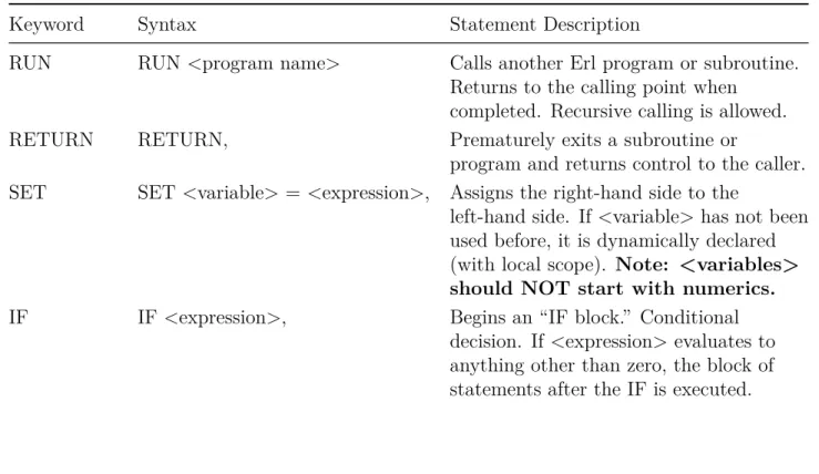
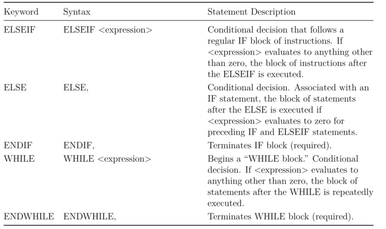
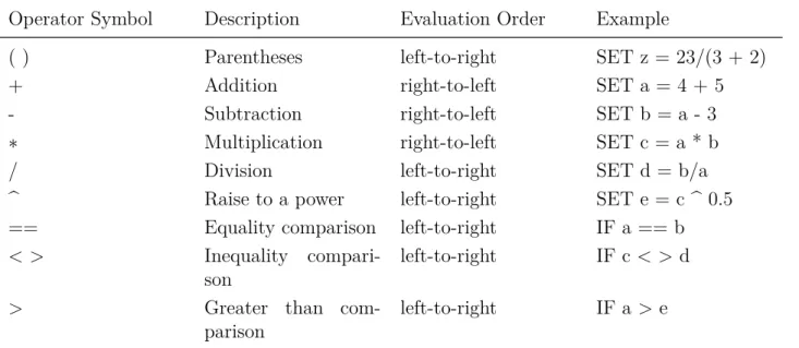
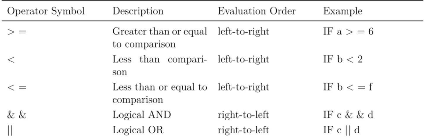
Rules for IF blocks
If there are many ELSEIF statements, the first one in the list that evaluates to true (1.0) is used, and execution jumps to the ENDIF for that IF block.
Rules for WHILE blocks
As with most EnergyPlus objects, each field is separated by a comma and usually given a separate line of text for readability. Each field starts with a keyword that identifies what that particular line of code is doing.
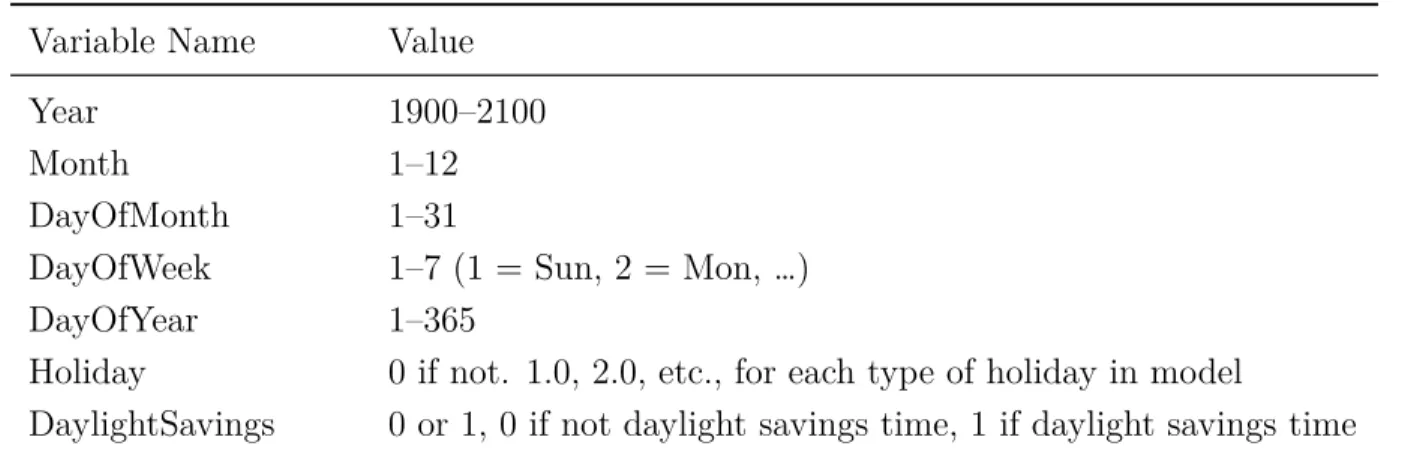
Variables
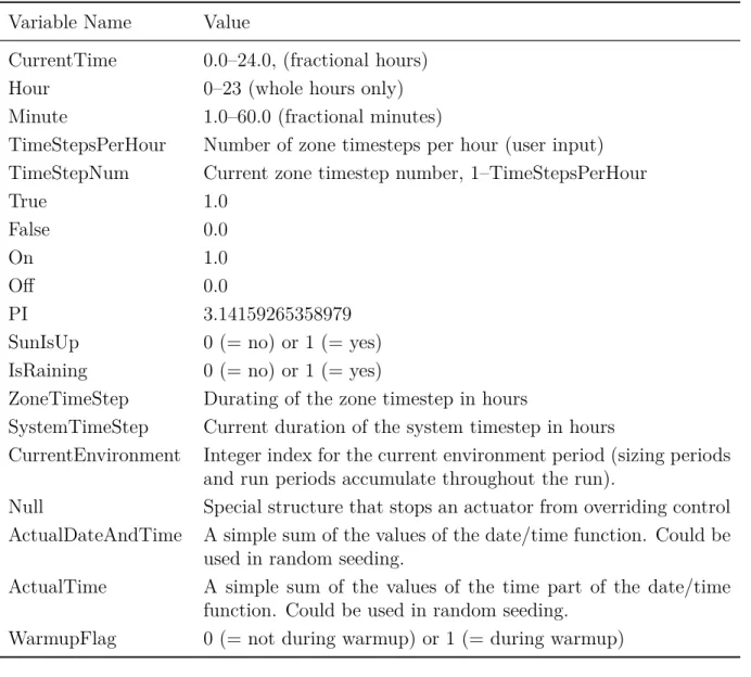
Built-In Variables
Null Special structure that prevents an actuator from overriding control ActualDateAndTime A simple sum of the values of the date/time function. ActualTime A simple sum of the values of the time portion of the date/time function.
Trend Variables
For exact index values, please check in the file eplusout.sql (table of EnvironmentPeriods) or see the order of the environment reports in the eio output. The logging of data is first-in-first-out, which means that the oldest data is pushed to the back of the log to make room for the newest data.
Expressions
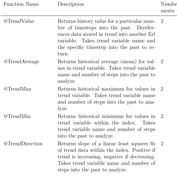
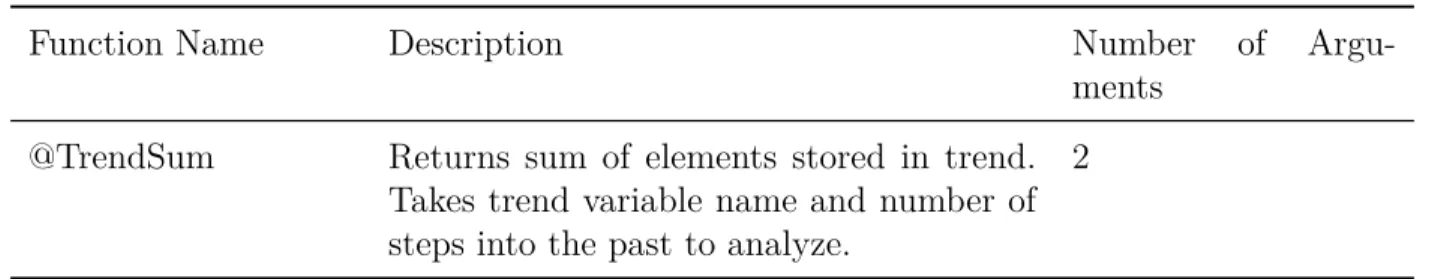
Trend variables differ from other Erl variables in that they can only be used by the built-in trend functions (see Table 2.6). Trend functions provide a number of ways to analyze trend data and extract data from the log.
Built-In Functions
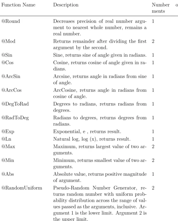
- Built-in Math Functions
- Built-In Simulation Management Functions
- Built-in Trend Variable Functions
- Built-in Psychrometric Functions
- Built-in Curve and Table Functions
- Built-in Weather Data Functions
The accessor functions listed in Table 2.6 are used to retrieve data from a trend variable during the execution of an Erl program. These differ from built-in variables in that they may or may not be created in each simulation and have user-defined names that distinguish between different instances of the same data type.
Internal Gains
People Count Design Level
Lighting Power Design Level
Plug and Process Power Design Level
Gas Process Power Design Level
Process District Heat Design Level
Process Steam District Heat Design Level
Other Equipment Design Level
Simple Zone Baseboard Capacity
HVAC Systems
- AirTerminal:SingleDuct:ConstantVolume:NoReheat
- Fan Nominal Ratings
- Unitary HVAC Nominal Ratings
- Outdoor Air Mixer Nominal Ratings
- Pump Nominal Ratings
- Unitary Systems
- Low Temperature Radiant Hydronic
- Boiler Nominal Ratings
- Chiller Nominal Ratings
The internal variable called "Pump Maximum Mass Flow Rate" provides information about the size of the pump. This internal variable is useful for scaling the flow rates applied to the "Water Mass Flow Rate" control in the.
On-Site Electricity Production
Generator Nominal Ratings
Electrical Storage
Sizing
Sizing:Zone
Sizing:System
Sizing:Plant
This output file is often needed to develop EMS inputs, so you may need to do an initial run of the model with traditional controls to get an RDD file. The RDD file from a similar model with the same types of components and systems can also be used as a guide to what will be available in a specific model.
Schedules
- System Node Setpoints
- Zone HVAC Control
- Plant Supervisory Control
- Outdoor Air System Node Conditions
- AirLoopHVAC Availability Status
- Ideal Loads Air System
- Fan
- DX Cooling Coils
- DX Thermal Storage Coils
- Unitary Equipment
- AirTerminal:SingleDuct:ConstantVolume:NoReheat
- Outdoor Air Controller
- Plant Equipment Operation
- Plant Load Profile
- Pump
- Window Air Conditioner
- Low Temperature Radiant Hydronic
- Variable Refrigerant Flow Heat Pump Air Conditioner
- Variable Refrigerant Flow Terminal Unit
An actuator named "AirLoopHVAC:UnitaryHeatPump:AirToAir" is available with the "Autosized Supply Air Flow Rate" control type. An actuator named "Pump" is available with control type "Pump Mass Flow Rate" (in kg/s).
Thermal Envelope
- Window Shading Control
- Slat Angle
- Surface Convection Heat Transfer Coefficient
- Material Surface Properties
- Surface Construction State
- Surface Boundary Conditions
- Conduction Finite Difference
Mass air temperature by convection." This is the temperature of the ambient air exposed to the surface, in degrees C. The coefficient of heat transfer by convection." This is the heat transfer coefficient, in W/(m-K) used for surface convection boundary conditions on the outer, outer, or other side of the surface.
Air Movement
- Zone Infiltration
- Zone Ventilation
- Zone Mixing
- Zone Cross Mixing
- Zone Refrigeration Door Mixing
- Zone Thermal Chimney
- Airflow Network Openings
An actuator called "Zone Thermal Chimney" is available with a control type called "Air Exchange Flow Rate" (m3/s). An actuator called "AirFlow Network Window/Door Opening" is available with a control type called "Venting Opening Factor". It is available in models that have operational openings in the Airflow Network model and are entered using either AirflowNetwork:MultiZone:Component:DetailedOpening, AirflowNetwork:MultiZone:Component:SimpleOpening, or AirflowNetwork:MultiZone:Component:HorizontalOpening input objects.
Internal Gains and Exterior Lights
People
Lights
Electric Equipment
Gas Equipment
Hot Water Equipment
Steam Equipment
Other Equipment
Baseboard
Exterior Lights
On-Site Electricity Production
Generator Dispatch
Electrical Storage
Refrigeration
Condenser Operation
General
Schedules
Curves
Weather Data
Sizing
Sizing:Zone
System Sizing
These EMS call points correspond to places within the EnergyPlus program where and when the EMS can be called to do something. EMS CALL POINTS Several time-step based call points shown schematically in Figure 6.2 will also be called.
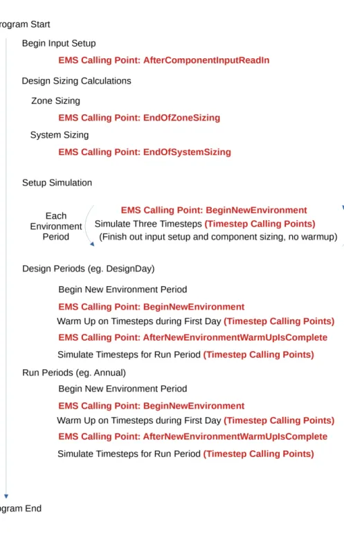
Begin Zone Timestep Before SetCurrentWeather
However, they are automatically reinitialized to 0.0 at the beginning of each new environment period, and this callpoint is executed again to repeat the initializations. Significant repetition can be avoided by designing Erl programs to use this call point for initializations and calculations that are needed only once for each environment period.
After New Environment Warmup Is Complete
This callpoint will not be useful for control actions, but is useful for initializing variables and calculations that do not need to be repeated at each time step. Once a value is set, Erl variables remember the value for the rest of the environment period.
Begin Zone Timestep Before Init Heat Balance
Begin Zone Timestep After Init Heat Balance
Begin Timestep Before Predictor
After Predictor Before HVAC Managers
However, if conflicts occur, EMS control actions may override other SetpointManager or AvailabilityManager actions.
After Predictor After HVAC Managers
Inside HVAC System Iteration Loop
End of Zone Timestep Before Reporting
End of Zone Timestep After Reporting
End of System Timestep Before HVAC Reporting
End of System Timestep After HVAC Reporting
End of Zone Sizing
End of System Sizing
After Component Model Input has Been Read In
User Defined Component Model
This section first introduces the common characteristics of user-defined component models and then goes into more detail on each of the available component model models that are used to connect user-defined models and algorithms to the rest of the simulations. of HVAC and EnergyPlus plant. While most EMS internal variables are constant, those intended for use with user-defined components are populated each time the component is simulated and change over time with the most current data available.
Zone Forced Air Unit
- Primary Air Connection
- Secondary Air Connection
- Plant Connections
- Water Use
- Ambient Zone
An actuator called "Secondary Air Connection" should be used, with control type "Outlet Humidity Ratio", at [kgWater/kgDryAir]. An actuator called "Secondary Air Connection" should be used, with control type "Outlet Mass Flow Rate", in [kg/s].
Air Terminal Unit
- Primary Air Connection
- Secondary Air Connection
- Plant Connections
- Water Use
- Ambient Zone
An actuator called “Plant ConnectionN” with control type “Outlet Temperature” should be used in [C]. An actuator called "Plant Connection N" with control type "Mass Flow Rate" in kg/s should be used.
Air Coil
- Air Connections
- Plant Connections
- Water Use
- Ambient Zone
An actuator named "Plant Connection" with the control type "Minimum Mass Flow Tempo," in [kg/s], must be used. An actuator named "Plant Connection" with the control type "Design Volume Flow Rate," in [m3/s], must be used.
Plant Component
- Plant Connections (User Defined)
- Plant Component (Temperature Source)
- Air Connection
- Water Use
- Ambient Zone
- Problem Statement
- EMS Design Discussion
- EMS Input Objects
An actuator called "air connection" with control type "output temperature" in [C] should be used. An actuator called "Air Connection" with control type "Outlet Mass Flow Rate" in [kg/s] should be used.
Example 2. Traditional Setpoint and Availability Managers
Problem Statement
EMS Design Discussion
Instead, we use a simpler temperature-based control to start and stop the air system for the night cycle. Then a series of logical statements are used to compare temperatures and decide what the availability status of the air system should be.
EMS Input Objects
To control the air system's operation status, we use an EnergyManagementSystem:Actuator object assigned to an "AirLoopHVAC" component type using the control variable called "Availability Status". EnergyPlus recognizes four availability conditions that govern the behavior of the air system. It then finds the maximum and minimum zone temperatures for all the zones connected to the air system.
Example 3. Hygro-thermal Window Opening Control for Airflow Network
Problem Statement
EMS Design Discussion
EMS Input Objects
Example 4. Halt Program Based on Constraint
Problem Statement
EMS Design Discussion
EMS Input Objects
Example 5. Computed Schedule
Problem Statement
EMS Design Discussion
EMS Input Objects
Example 6. Window Shade Control
Problem Statement
EMS Design Discussion
When the direct incidence angle of the sun is less than 45 degrees, we want to tighten the curtain. Although the user-defined name for the WindowShadingControl is "INCIDENT SOLAR ON BLIND", the unique name of the actuator component that is available is called.
EMS Input Objects
Set Zn001_Wall001_Win001_Shading_Deploy_Status = Shade_Status_Interior_Blind_On , ELSEIF Zone_Sensible_Cool_Rate > 20, . Power Scheme:GlobalVariable , Shade_Status_Interior_Shade_On ; Power Scheme:GlobalVariable , Shade_Status_Switchable_Dark ; Power Scheme:GlobalVariable , Shade_Status_Exterior_Shade_On ; Power Scheme:GlobalVariable , Shade_Status_Interior_Blind_On ; Power Scheme:GlobalVariable , Shade_Status_Exterior_Blind_On ; Power Scheme:GlobalVariable , Shade_Status_Between_Glass_Shade_On ; Power Scheme:GlobalVariable , Shade_Status_Between_Glass_Blind_On.
Example 7. Constant Volume Purchased Air System
Problem Statement
EMS Design Discussion
EMS Input Objects
Example 8. System Sizing with Discrete Package Sizes
Problem Statement
EMS Design Discussion
To obtain this result for use in an Erl program, we use an EnergyManagementSystem:InternalVariable input object to set up a variable for the data called "Intermediate air system main supply volume flow rate." We can then use this value in our algorithm to find a discrete system size. For this we use an EnergyManagementSystem:Actuator input object to establish control over "Sizing:System" type component using "Main Supply Volume Flow Rate" control type.
EMS Input Objects
The EMS call point for air system sizing is called "EndOfSystemSizing". So we put this in the program's call manager. For this example, we modify the example file named "RefBldgStripMallNew2004_Chicago.idf". This file has 10 separate packed units, so instead of repeating the algorithm several times, we use a subroutine so that the same Erl code can be reused for each air system.
Example 9. Demand Management
Problem Statement
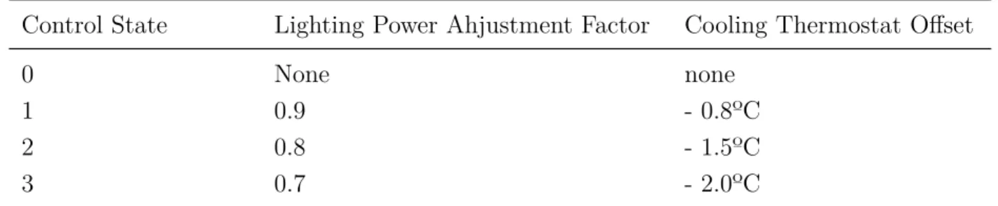
EMS Design Discussion
The control state determination Erl program determines the current status of the demand management controls. Once the control state is determined, the Erl programs will use EMS actuators to override controls based on the state.
EMS Input Objects
Therefore, we make a copy of the cooling setpoint schedule, named CLGSETP_SCH_Copy, and use the copy in an EnergyManagementSystem:Sensor object to get the current scheduled setpoint value. SET Set_Cooling_Setpoint_Sched = Null, SET Set_Basement_Lights = Null, SET Set_Core_bottom_Lights = Null, SET Set_Core_mid_Lights = Null, SET Set_Core_top_Lights = Null, SET Set_Perimeter_bot_ZN_3_Lights = Null, SET Set_Perimeter_bot_ZN_2_Lights = Nu ll, SET Set_Per meter_bot_ZN_1_Lights = Null, SET Set_Perimeter_bot_ZN_4_Lights = Null, SET Set_Perimeter_mid_ZN_3_Lights = Null , SET Set_Perimeter_mid_ZN_2_Lights = Null, SET Set_Perimeter_mid_ZN_1_Lights = Null, SET Set_Perimeter_mid_ZN_4_Lights = Null, SET Set_Perimeter_top_ZN_3_Lights = Null, SET Set_Perimeter_top_ZN_2_Lights = Null, SET Set_Perimeter_top_ZN_1_Lights = Null , SET Set_Perimeter_top_ZN_4_Lights = Null;.
Example 10. Plant Loop Override Control
Problem Statement
Core_bottom_Lights, !- Internal Data Index Key Name Lighting Power Design Level; !- Internal data type.
EMS Design Discussion
If the outside temperature of the dry bulb falls below a certain value, the loop and pump actuators are set to zero. When modifying this specific input file, it was found that the external dry bulb temperature that removed these warnings was six degrees Celsius.
EMS Input Objects
If the outside temperature is equal to or higher than this value, the actuators are set to Null, returning control to normal operating patterns. We also create a custom output variable called “EMS Condenser Flow Override On” to easily record when overrides have occurred.
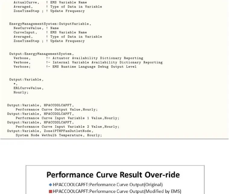
Example 11. Performance Curve Result Override
Problem Statement
EMS Design Discussion
Zone1PTHPOAMixerOutletNode , !- Mixed Air Node Name Zone1PTHPOAInNode , !- Outdoor Air Stream Node Name Zone1PTHPExhNode , !- Relief Air Stream Node Name Zone1PTHPAirInletNode; !- Return Air Stream Node Name. Note that the Total Cooling Capacity function of Temperature curve name is HPACCool-CapFT and the inlet air node for this cooling coil is Zone1PTHPFanOutletNode.
EMS Input Objects
Zone1PTHPFanOutletNode , !- Output:Variable or Output: Meter Index Key Name System Name Node Temperature; !- Output: Variable or Output: Meter Name. Zone1PTHPOAInNode , !- Output:Variable or Output: Meter index System key name Node temperature; !- Output: Variable or Output: Meter Name.
Example 12. Variable Refrigerant Flow System Override
Problem Statement
EMS Design Discussion
EMS Input Objects
Example 13. Surface Construction Actuator for Thermochromic Window
Problem Statement
EMS Design Discussion
The temperature of the glazing is used in a long block IF-ELSEIF-ELSE-ENDIF to select the correct construction to allocate the surface. Here we use the temperature of the outside surface because it is closer to the temperature of the center pane (which can be much higher in direct sunlight).
EMS Input Objects
The original thermochromic example file already contains a series of WindowMaterial:Glazing input objects that correspond to the properties of the thermochromic glass at different temperatures. In this case, the native thermochromic model has an important advantage in that the dedicated model can access the temperature of the middle pane in a triple-glazed window, while the EMS model can only access the temperature of the outer or inner pane.
EDD File
Line Trace
Debugging Strategies