Intrinsically safe toxic and oxygen gas detector
Introduction
The installation must be in accordance with the recognized standards of the relevant authority in the country concerned. The detector must be mounted where the gas to be detected is most likely to be present. To detect lighter-than-air gases, detectors should be mounted at high level and Crowcon recommends the use of a Collector Cone (Part No. C01051) and Accessory Adapter (Part No. M04666).
For outdoor mounted detectors, Crowcon recommends using a Deflector Spray (Part No. C01052) and additional adapter (Part No. M04666). For example, ammonia is normally lighter than air, but if it is released from a cooling system, the gas may fall instead of rise. Sensor placement should be determined following the advice of experts who have specialized knowledge of gas distribution, plant processing equipment, and safety and engineering issues.
Installation
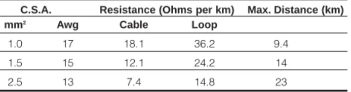
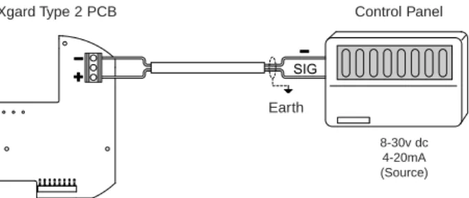
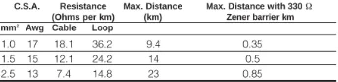
Care must be taken when installing the detector to avoid damaging the painted surface of the junction box and sensor holder. Cables for Xgard must conform to the recognized standards of the relevant authority in the country concerned and meet the electrical requirements of the detector. Ensure that there is a minimum of 8 volts at the detector, taking into account the voltage drop due to the cable resistance, the Zener barrier (if fitted) and the sensing resistance of the control panel to which it is connected.
The table is a guide only, actual cable parameters for each application must be used to calculate maximum cable distances. The terminals are marked '+' and '-' and correct polarity must be observed when connecting the detector to control equipment. Open the detector junction box by unscrewing the cover anti-clockwise (after loosening the retaining screw first).
Apply power to the detector and ensure that the minimum supply voltage of 8 V DC is present at the '+' and '-' terminals of the detector. Apply calibration gas (concentration should be at least 50% of sensor full scale) to the detector at a flow rate of 0.5 - 1 liter/minute via a flow adapter (Part No. C03005).
Operation
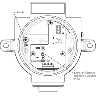
Adjust the 'ZERO' pot on the amplifier (which is accessible via a hole in the PCB cover) until the DVM reads 40 mV. Allow the gas reading to stabilize (usually 30 to 60 seconds) and adjust the 'CAL' pot until the DVM reads the appropriate reading. 11. Close the detector junction box, making sure the lid is securely tightened and the thumb screw is attached.
Remove the amplifier PCB cover and move the LINK on the amplifier board from 'RUN' to 'SET ZERO'. The operating life of the sensors depends on the application, frequency and amount of gas seen. Under normal conditions (6-month calibration with periodic exposure to CAL gas) the lifetime of toxic sensors is 2-3 years.
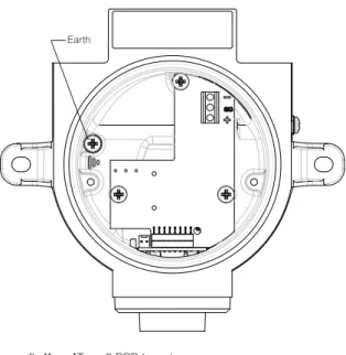
15 When performing maintenance on Xgard, ensure that the sensor holder and the junction box cover O-rings are present and in good condition to maintain the intrusive protection of the product. Fit the replacement sensor (after checking that the part number matches what is stated on the detector junction box label), ensuring that the locating pins are correctly aligned with the slots in the junction box.
Specification
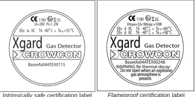
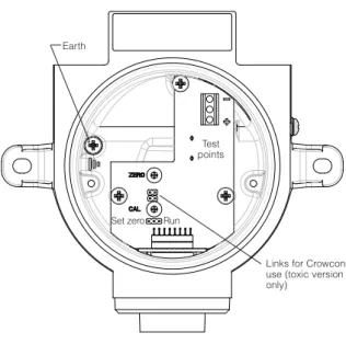
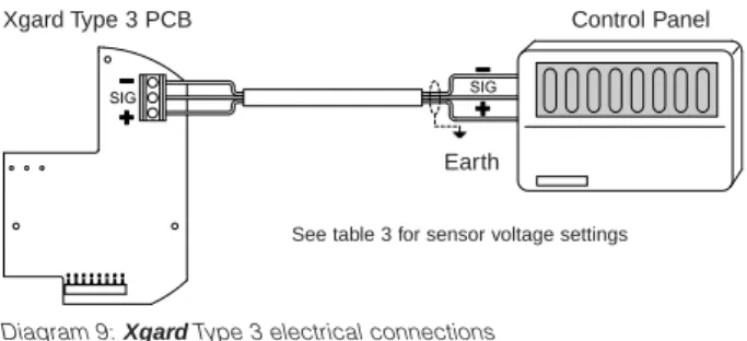
The detector is certified II 2 G EExd IIC T6, and is suitable for use in zone 1 and zone 2 hazardous areas. Electrical connections to the detector are made via the terminal strip on the amplifier's circuit board shown below. Electrical connections to the detector are made via the terminal strip on the printed circuit board shown below.
This will vary depending on the part number of the sensor fitted (see 'Sensor Type' on the label fitted to the junction box). The terminals are marked '+', 'sig' and '-' and correct polarity must be observed when connecting the detector to control equipment. 10. Close the detector junction box, making sure the lid is securely tightened and the thumb screw is attached.
This version of Xgardis a high temperature (150°C / 302°F) flame resistant gas detector designed to detect flammable gas present in ambient air in concentrations not exceeding the lower explosive limit (LEL) of the target gas for which it is calibrated. . The detector is certified II 2 G EExd IIC T3 and is suitable for use in hazardous areas of Zone 1 and Zone 2. Measure the voltage at the "+" and "-" terminals and adjust according to the type of pellistor installed (see Table 5 ).
Close the detector junction box, making sure the lid is securely tightened and the tip screw is secured. The detector relies on there being a significant difference in the thermal conductivity properties of the gases in the mixture being monitored. The Xgard Type 6 is powered by 24vDC (nominal) and provides a 4-20mA signal (sink or source) proportional to the gas concentration.
12. Close the detector junction box and make sure the cover is securely screwed on and the fitting is in place. The lifetime of the sensor depends on the application for which it is used. Sensors are prone to damage from vibration and shock, so steps must be taken to ensure that these influences do not affect the detector.
The supply voltage should be set to 6.5 Vdc, measured between the '+' and '-' terminals of the detector (observe correct polarity, as incorrect connection will damage the sensor). Connect a digital voltmeter (DVM) to the test points on the amplifier PCB as shown in Figure 16. It is strongly recommended that the head voltage potentiometer on the control card be set to minimum before connecting the detector.
Changes in electrochemical sensor performance at extreme temperatures; contact Crowcon if the detector will be exposed to ambient temperatures below -20°C or above +40°C (-4 and 104°F).
Flameproof toxic and oxygen gas detector
Flameproof flammable gas detector
Flameproof high temperature flammable gas detector . .33
Flameproof flammable gas detector with 4-20mA output .41
Flameproof thermal conductivity type gas detector
Flameproof Sulphistor hydrogen sulphide gas detector .59