The data may undergo changes deemed necessary to improve the product at any time and without obligation to any notice thereof. Risks to the safety of the user or third parties or even damage to the devices and other objects may still occur in case of incorrect use. Provide the following installation instructions with all the supplementary documentation to the user of the device, who is responsible for keeping the instructions so that they are always available when needed.
It is forbidden to pull, disconnect or twist the electrical cables of the unit, even if it has been disconnected from the mains.
Warnings on the documentation
Intended use
Conserving the documentation
Essential safety rules
Product identification
Description of the unit
Available models
Depending on the characteristics of the selected pump, it provides a useful head to overcome the pressure drop in the system. DRE Allows to reduce the starting current required by the machine during the start-up phase. It is advisable to keep a machine book (not supplied, but provided by the user), to keep track of the operations on the unit.
Check the operation of the high and low pressure switches; replace them if they malfunction.
Available versions
Configurator
Y Mechanical thermostatic valve low water temperature (down to -6°C) X Electronic thermostatic valve also for low water temperature (down to -6°C). 01 Low-head water accumulator and single pump 02 Low-head water accumulator and stand-by pump 03 High-head water accumulator and single pump 04 High-head water accumulator and stand-by pump. 05 Water accumulator with holes for additional electric heater, low head and single pump 06 Water accumulator with holes for additional electric heater, low head and backup pump 07 Water accumulator with holes for additional electric heater, high head and single pump 08 Water accumulator with holes for additional electric heater, high head and backup pump 09 Double hydraulic ring.
P2 Without water accumulator, with low head pump and backup pump P3 Without water accumulator, with high head pump.
Description of components
- Nrl 0750 - 1250 high efficiency
- Nrl 1400 - 1800 high efficiency
- Chiller circuits, hydraulic (A - E)
- Chiller circuits, hydraulic (HA - HE)
- Chiller circuit
- Frame and fans
- Hydraulic components
- Safety and control components
- Electrical components
Plate type (AISI 316), externally insulated with closed-cell material to reduce thermal dispersion. Fixed calibration, located on the low pressure side of the refrigeration circuit, stops the operation of the compressor in case of abnormal operating pressures. With a fixed calibration installed on the high-pressure side of the refrigeration circuit, it shuts down the compressor in case of abnormal working pressure.
Located on the high pressure side of the chiller circuit, it communicates the operating pressure to the control card and sends a pre-alarm in case of abnormal pressure.
Accessories
The electrical panel can be accessed by disconnecting the power and then using the opening lever on the panel itself. TP2 Enables the compressor suction pressure value to be displayed (one per circuit) on the microprocessor card display. Placed on the low-pressure side of the refrigeration circuit, it shuts down the compressor in case of abnormal operating pressure.
It consists of an electronic control card that varies the speed of the fan based on the condensing pressure (read by the high pressure transducer) to keep it high enough for the proper operation of the unit.
Technical data
Technical data versions (A - E)
Technical data versions (HA - HE)
Operating limits
Cooling mode
Heating mode
Correction factors
- Cooling capacity and input power
- Heating capacity and input power
- For ∆t different from the rated value
- Fouling factors
The heat capacity achieved and the electrical input capacity under conditions other than the nominal conditions are obtained by multiplying the rated values (Pt, Pa) by the respective correction coefficients (Ct, Ca). The chart allows you to get the correction coefficients; in line with each curve you will see the heat treated water temperature to which it refers, assuming a 5°C condenser inlet and outlet temperature difference. To obtain correction factors for a cooling capacity and input power different from ∆t 5°C, use Table 9.3.1.
The performance levels shown in the technical data refer to conditions with clean pipes, with a contamination factor = 1.
Ethylene glycol solution
How to read the glycol curves
Pressure drops
Total pressure drops
Useful heads
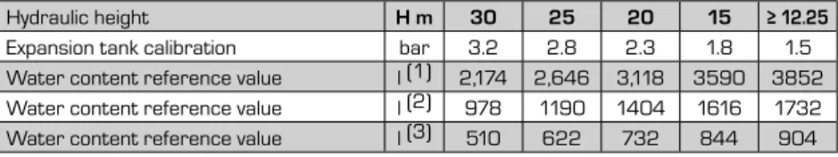
Accumulation
Maximum/minimum water content in the system
Minimum water content recommended
Capacity control
Desuperheater
Pressure drops
Sound data
Safety and check parameter setting
Dimensions
Minimum technical clearances
Position of plumbing connections position of vibration dampers
Nrl 750 high efficiency
Nrl 1650 - 1800 high efficiency
Nrl 0750 desuperheater (high efficiency)
Weight distribution and centres of gravity
Percentage weight distribution
Percentage weight distribution
Safety warnings and regulations
Receiving the product
Transport and handling
Positioning
Handling example
Hydraulic circuits
Internal hydraulic circuit nrl "00"
Internal hydraulic circuit nrl" P1-P2-P3-P4"
It must be kept clean, so it is necessary to check its clean condition after installing the unit and check it regularly. You are advised to check the characteristics of the mains supply to ensure that it is suitable for the levels indicated in the electrical data table, also taking into account any other equipment that may be operating at the same time. Check that the general power supply cables are of a suitable section, can withstand the overall absorption of the unit (see electrical data), and that the unit is properly earthed.
Check that the electric heater(s) of the compressor casing is working by measuring the rise in temperature in the oil sump. At least 24 hours before starting the unit (or at the end of each period of prolonged inactivity), the unit must be started to allow the compressor crankcase heaters to evaporate any refrigerant present in the oil. Check the correct operation of the flow switch: if the shut-off valve at the heat exchanger outlet is closed, the shut-off alarm should appear on the screen.
Commissioning of machines must be agreed in advance based on the system build times. Before the intervention of the AERMEC After Sales Service department, all works (electrical and sanitary connections, filling and venting of the installation) must be completed. Record in the booklet the date, the type of operation performed (routine maintenance, inspection or repair), description of the operation, measures taken.
Check that the screws on the fan grills (and the fans themselves) are tight, as well as the compressors and electrical box and the unit's outer panels. Accidental opening of the electrical panel with the machine in operation is prevented by the door lock's sectioning device.
Internal hydraulic circuit nrl "01-02-03-04-05-06-07-08" .44
Filter maintenance
- Filter cleaning procedure
- Lines and electric data for the unit
- Electrical data
- Connection to the electrical power supply
Loosen the hex nut on the filter head, remove the metal ring nut and clean it. Replace the ring nut on the filter housing and retighten the hex nut. type of filter mounted only on the version with water accumulator and pump). The presence of the filter should be considered mandatory and its removal will void the warranty.
The installation of the shut-off valves is recommended to be able to disconnect the machine from the system, or for maintenance operations. The selection and installation of components apart from the NRL is the responsibility of the installer, who must. The hydraulic pipes for connection to the machine must be properly sized for the actual water flow rate required by the plant during operation.
Check that all power cables are correctly attached to the terminals when it is first switched on and after 30 days of use. The wiring diagram together with the manuals must be kept in good condition and readily ACCESSIBLE FOR FUTURE OPERATIONS ON THE UNIT. The units are fully wired in the factory, so only need to be connected to the mains.
2 Turn the door lock release switch handle to OFF, then lock and set the warning notice.
Start-up
Preliminary operations
Start-up
The refrigerant gas: The gas must be removed with suction devices that work in a closed circuit so that there is no gas leakage into the environment. Disposal of refrigerant gas, possibly glycol water and any other material or substance must be carried out by qualified personnel and in accordance with the applicable legislation in order to avoid damage to things or people or contamination of the surrounding area. When awaiting disposal, the unit can also be stored outdoors, as exposure to the elements and temperature changes will not cause harmful effects to the environment as long as the unit's electrical, cooling and hydraulic circuits are closed and in good condition.
During the disassembly phase, the fan, motor and coil, if working, can be taken from specialized centers for possible reuse. Do not insert or allow objects to fall through the fan motor grills. The machine must not exceed the limit values of pressure and temperature, which are indicated in the table in the chapter "Operational limits".
The machine is equipped with safety valves which, in case of excessive pressure, can discharge high-temperature gases into the atmosphere. In case of contact with the liquid, warm the frozen tissue with water and call a doctor. Skin contact: if the skin comes into contact with the rapidly evaporating liquid, it may cause tissue freezing.
In case of fire or overheating, there is an increase in pressure and the container may explode. Greenhouse effect potential of halogenated hydrocarbons: HGWP (R Bio-accumulation Virtually non-biaccumulative: log Pow = 0.21.
Loading and draining the system
Maintenance
All routine and emergency maintenance operations must be performed by qualified personnel only. Before starting any cleaning or maintenance operation, it is advisable to disconnect the unit from the power supply. Check the seal of the coolant circuit and make sure that the pipes in it are not damaged.
Disposal
Disconnecting the unit
Dismantling and disposal
Improper use
Important safety information
Refrigerant gas R410a
Possibility of the occurrence of hazardous reactions in the event of a fire due to the presence of F and/or CI groups. However, it can become flammable when mixed with compressed air and exposed to strong sources of ignition. The vapors are heavier than air and can cause suffocation, making less oxygen available for breathing.
Contiene gas fluorurati con effetto invernale regolati dal Protocollo di Kyoto R410A (Potencial de calontamiento atmosférico 1980). Contient des gaz à effet de serra fluorés relativo al protocollo di Kyoto R410A (Potentiel de rehautement planetaire 1980). Contiene gas fluorurati ad effetto serra contemplati dal Protocollo di Kyoto R410A (Global Warming Potential 1980).
Contém gases fluorados com efeito de estufa abrangidos pelo Protocolo de Quioto R410A (Potencial de Aquecimento Global 1980).