The installation, connection, operation and maintenance of the device is carried out by qualified personnel in accordance with the instructions contained in this manual. For unloading the units, please observe the procedures as indicated in the illustrations below, which are also affixed to the original packaging of the unit.
SHOCK-ABSORBING FEET
RAIN CANOPY
WATER CONNECTIONS
- CONDENSATE DRAIN AND SIPHONS
- WATER-COOLED CONDENSERS
- WATER COILS
- HEAT RECOVERY CIRCUIT
- INTERNAL ELECTRODE HUMIDIFIER
- MAINS STEAM VALVE
The diameters of the pipes and the inlet and outlet connections are indicated in the order confirmation. A shut-off damper (to be supplied by the installer) must be installed upstream of the system.
REFRIGERANT CIRCUIT CONNECTIONS
- DISCHARGE OR HOT GAS LINE
- LIQUID OR RETURN LINE
- NON-RETURN VALVES ON DISCHARGE AND RETURN LINES
- VERY LOW EXTERNAL TEMPERATURE KIT
- SOLENOID VALVE ON THE LIQUID LINE
- ROUTING OF THE REFRIGERANT CIRCUIT PIPES
- DIAMETERS OF REFRIGERANT CIRCUIT CONNECTION PIPES
- REFRIGERANT CHARGING
CEA air condensers, combined with Tecnair LV air conditioners with direct expansion, are equipped as standard with air condensation pressure regulation via reduction of the air flow rate in accordance with the reduction of the condensation pressure. At external temperatures below this level and above all in the case of longer periods without use of the cooling circuit, the temperature of the liquid refrigerant can become so low that the low-pressure pressostat is triggered despite the above-mentioned delay. when starting the compressor, which makes starting impossible. To avoid this problem, we recommend the "very low temperature kit", which consists of a condenser flood valve installed on the refrigerant connections of the air condenser.
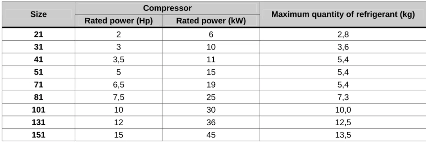
It is therefore necessary to compare the refrigerant charge in the circuit, calculated as the sum of the contents of the various components of the circuit, with the maximum amount compatible with proper operation without the solenoid valve in the liquid pipe, as shown in the table. lower. Correct routing of the refrigerant circuit pipes is essential for the successful operation of the air conditioner. The counter-siphon should be at least as high as the highest part of the condenser coil;.
Pipe supports must prevent the transmission of vibrations and at the same time allow for the normal expansion and contraction of pipes due to temperature changes during operation. A 1/4" service valve should be installed on both pipes, as close as possible to the outdoor unit, to allow draining and charging of the circuit. It is also necessary to add oil to the circuit in an equal amount with approximately 5% of the total amount of coolant in the circuit.
ELECTRICAL CONNECTIONS
- INSTALLATION OF THE REMOTE CONTROL INTERFACE
- INSTALLATION OF THE TEMPERATURE/HUMIDITY SENSOR SUPPLIED WITH THE UNIT
- INSTALLATION OF THE AMBIENT DIFFERENTIAL PRESSURE SWITCH
- POSITIONING OF THE AMBIENT DIFFERENTIAL PRESSURE SWITCH
If the full terminal or reduced version is to be mounted in a panel or in a niche, the maximum thickness of the panel must be 6 mm; if the terminal is to be flush mounted in a wall, a masonry box must be provided with internal dimensions sufficient for the terminal and connecting cables. The user terminal must be connected to the motherboard via a 6-wire telephone cable. To establish the connection, it is enough to insert one of the telephone connectors into one of the terminals of the TCON6 board, and the other into the terminal connector, as shown in the wiring diagram.
For a secure connection, use the toroid that comes with the user terminal to avoid interference on the line that could damage the memory or components of the board itself. Installation within the supply air duct at the point closest to the outlet vents. The humidity sensor must be installed on the machine in the return air area.
The differential pressure switch installed in the room to be controlled is fundamental as it continuously transmits the measured ambient pressure to the microprocessor controller. The pressure switch uses two air inlets and an electrical terminal block that connects to the electrical panel terminal block with a shielded 3x0.35 cable (AWG22) as shown in the wiring diagram. Connect the pipe with the free end in the room to the positive socket of the differential pressure switch, even if there is negative pressure in the room, which protrudes a few centimeters from the wall or ceiling.
5 CHECKS AND FIRST STARTUP
DATE PLACE
OPERATOR’S SIGNATURE
CUSTOMER’S SIGNATURE
REFRIGERANT CIRCUIT CHECKS
10 Check that the refrigerant circuit valves are open, including the valve on the hot gas injection line. Check that the refrigerant piping connections between the condenser and the evaporator are in the opposite direction of the airflow and refrigerant flow. Check that the condenser is positioned correctly, well away from walls and/or other condensers to prevent recirculating air currents that could impede operation.
WATER CIRCUIT CHECKS
ELECTRICAL POWER SUPPLY CHECKS
NOTES ON ANOMALIES ENCOUNTERED DURING CHECKS
6 DEACTIVATION, DISASSEMBLY AND SCRAPPING
7 USE OF THE AIR CONDITIONING UNIT
- TEMPERATURE CONTROL
- PROPORTIONAL CONTROL
- PROPORTIONAL + INTEGRAL CONTROL
- PROPORTIONAL + INTEGRAL + DERIVATIVE CONTROL
- SERIES H DIRECT EXPANSION AIR CONDITIONERS
- CHILLED WATER AIR CONDITIONER
- COOLING CAPACITY CONTROL WITH HOT GAS INJECTION VALVE
- COOLING CAPACITY CONTROL WITH HOT GAS INJECTION VALVE AND ELECTRONIC EXPANSION VALVE
- HUMIDITY CONTROL
- SERIES H DIRECT EXPANSION AIR CONDITIONERS
- CHILLED WATER AIR CONDITIONER
- SIMULTANEOUS HUMIDIFICATION AND COOLING
- DEHUMIDIFICATION LOCK
- SPECIFIC FUNCTIONS OF THE CONTROL SOFTWARE
- NIGHT-TIME STAND-BY
- UPS CONNECTION
- SUPPLY TEMPERATURE CONTROL (LIMIT)
- ANTIFREEZE SYSTEM
- STERILIZATION CYCLE
- UNIT SHUTDOWN: in this stage the unit is shut down completely so as to allow the sterilizing agent to work. (Default 1 hour)
- WASHING: the unit activates both fans at 100% and shuts completely the recirculation damper
- EMERGENCY OPERATION WITH UNIT IN NEGATIVE PRESSURE
The injection of hot gas downstream of the thermostatic valve reduces the cooling capacity in proportion to the demand from the control system. The electronic expansion valve (EEV) allows superheat control in the intake line for more efficient and versatile operation of the cooling system. Once the component has been activated, the control continues by adjusting the cooling capacity, in the case of hot gas bypass or water cooled coil, to the set point.
The cooling capacity is never lowered below 60% of the total to allow the effect of dehumidification. If the air conditioner is dehumidifying and the temperature is above 150% of the proportional band, the microprocessor will inhibit dehumidification and give priority to temperature control. Refer to the installation manual supplied with the unit for more detailed descriptions of the components and accessories involved in the processes.
In the event of an emergency, standby can be deactivated at any time to restore normal operation of the unit. If the unit is connected to a UPS system via the specific digital input (see connection diagram), it will be possible to reduce the unit's electricity consumption to a minimum, while still guaranteeing the sterility of the air in the room. In this way, the sterilizing agent reaches and saturates all components of the aeraulic circuit.
8 ROUTINE AND MAJOR MAINTENANCE
- PROGRAMMED MAINTENANCE CHART
- MAINTENANCE OF THE FANS
- REFRIGERATION CIRCUIT CHECKS
- MAINTENANCE OF THE ELECTRICAL BATTERY
- MAINTENANCE OF THE ELECTRICAL PANEL
- MAINTENANCE OF THE AIR FILTERS
Check the calibration and operation of the control valves X Check the refrigerant charge level and for leaks in the circuit X REFRIGERANT. Check remote condenser controller calibration X Check remote condenser is properly powered X Check water cooled condenser pressure control valve X CONDENSERS. Maintenance work on the fan must be carried out under maximum safety and always with the unit switched off.
Regularly check that the fan blades are clean and remove all dirt and encrusted deposits that can affect the balance of the rotor and thus damage the bearings. It is sufficient to check that the battery is clean and that the current consumption in amperes corresponds to the specifications in the technical data sheet. If the machine is equipped with a modulating electric battery, it is advisable to also check from time to time that the modulator is working properly.
To do this, it is enough to check that the machine behaves correctly during the heating operation, with the relative side of the screen showing a voltage of 0-10 V for the output of the microprocessor to the modulator. To ensure the effectiveness of the filters, it is necessary to install a 15x3 mm gasket. We also recommend the installation of an external air pre-filtration system with an efficiency of at least G3 to avoid frequent clogging of the F6 filters and thereby reduce the operating costs of the system.
9 WASHING, CLEANING AND DISINFECTION
- WARNINGS
- CLOTHING TO BE WORN DURING CLEANING OPERATIONS
- CLEANING SYSTEMS
- TECHNICAL COMPARTMENT: the part of the air conditioner containing the control systems and the compressors. In this zone there is no air circulation and therefore disinfection is not normally required
- EXTERIOR OF THE AIR CONDITIONER: the exterior of the unit is made from enamelled sheet steel and should only be cleaned in accordance with the criteria and the procedures specifically indicated in this manual
- DISPOSAL OF USED CLEANING MATERIALS
Since air conditioners contain electrical components (electric motors, terminal blocks, sensors, etc.) that can be damaged by high-pressure water jets or high temperatures, and a cooling system that should not be subjected to high pressures, the use of steam or pressurized water for cleaning operations is strictly prohibited. Unless otherwise indicated by the physician in charge of the room, used vacuum cleaner filters should not necessarily be disposed of as contaminated waste. This area is subject to an outside air leak in the operating room after appropriate treatment and at the site of the leak.
Despite the filtration systems present in the air intake, return and distribution system and in the air conditioner itself, this zone can harbor bacteria that can spread when the unit is inactive, creating a health hazard the next time the unit is put into use . However, as the frequency and manner in which operating rooms are used can vary widely, the responsibility for deciding when washing and disinfection of these rooms is necessary rests solely with the person in charge of the medical department. Remove the preheat water coil (if present) as it may otherwise limit the effectiveness of any cleaning of the cold coil.
If the air conditioning unit is installed inside the operating room or in a room that is connected (anesthesia room, recovery room, post-operative observation room, etc.), its exterior must be cleaned and disinfected at the same time as its operating rooms, unless the head of the department determines otherwise. If the unit is installed in a technical room that is not connected to the operating room, it is enough to clean the exterior when traces of dust or grease are visible. When cleaning air conditioners, solid (old filters, operator's clothing, worn drive belts, etc.) and liquid waste materials (remains of washing liquid and rinsing water) are produced.
10 FAULT DIAGNOSIS
- MALFUNCTION OF THE FAN CONTROL INVERTER
- DIRECT EXPANSION AIR CONDITIONERS – REFRIGERATION CIRCUIT PROBLEMS
- CHILLED WATER AIR CONDITIONERS – WATER CIRCUIT PROBLEMS
- HEATING SECTION PROBLEMS
- DEHUMIDIFICATION PROBLEMS
- VENTILATION PROBLEMS
The following table shows the fault codes, causes and remedies for problems with fan control inverters. The inverter has detected that the current at the output terminals is too high (>4*IH) Sudden increase in the load. In case of temporary interruption of the power supply, reset the fault and restart the inverter.
Current measurement has determined that there is no current on one of the motor phases. Check that the commutation frequency is not too high in relation to the ambient temperature and the load on the motor. The thermistor input on the optional board has detected an increase in motor temperature.
Check the thermistor connection (if the thermistor input of the optional board is not used, it should be shorted).
11 GLOSSARY
12 NOTES
