Do not use chemical products or solvents to clean any part of the fan coil unit. Do not spray water on the external or internal surfaces of the fan coil unit (this may cause short circuits). In cooling mode, water vapor may be present in the air supply of the fan coil unit.
Water probe upstream of the valve: the probe measures the temperature of the water in the system. SW4 probe: As an optional extra, a probe can be installed to measure the temperature of the water in the system. With the help of the flanges (accessories), the ducts (for renewal of the ambient air and/or delivery to an adjacent room) can be connected to the sides.
Performance values refer to the following conditions:. at the maximum motor speed;. the total input power is determined by adding the input power for the unit to the input power for the accessories connected and explained in the corresponding manuals. The sound pressure and power levels of the fan coils at the different speeds are shown in the tables.
FCL (Standard)
4-pipe system2-pipe system
FCL (V2)
FCL (Standard) with electric heater 4-pipe system
FCL (V2) with electric heater 4-pipe system
FCL (VL) without valves
RXLE
Only for models and confi gurations
Performance certified EUROVENT 6/3 - Acoustic tests certified EUROVENT 8/2 (ISO 3741/2001)
C] = wet bulb inlet air temperature Ta D.B.[°C] = dry bulb inlet air temperature Pc [w] = total cooling capacity. If significant power values are above the total power, this means that cooling is carried out without dehumidification. To determine the cooling capacity according to the speed (air flow), the values shown in the table must be multiplied by the following factors (k):.
COOLING CAPACITY CORRECTION FACTORS
COOLING CAPACITY CORRECTION FACTORS 5
COOLING CAPACITY CORRECTION FACTORS 11
HEATING CAPACITY CORRECTION FACTORS
FCL 102
FCL 104
FCL 122
FCL 124
Pressure drops [kPa] with water 50°C
Water fl ow rate [l/h] FCL32 FCL36 FCL42 FCL62 FCL72 FCL82 FCL102 FCL122
Pressure drops [kPa] with water 70°C
Water fl ow rate [l/h] FCL34 FCL38 FCL44 FCL64 FCL84 FCL104 FCL124
Pressure drops [kPa] with water 7°C
GLYCOL WATER AT 10%
GLYCOL WATER AT 35%
GLYCOL WATER AT 20%
COOLING FUNCTION MODE HEATING FUNCTION MODE
FCL34
FCL36 FCL38
FCL42 FCL44
FCL62 FCL64
FCL72
FCL82 FCL84
FCL102 FCL104
FCL122 FCL124
SOUND PRESSURE LEVEL expressed in db (a)
Suction and delivery grille units
Standard control panels (electronic and electromechanical)
Intake and delivery grille units with electronic thermostat incorporated for the VMF System
Wall-mounted control panel for the VMF System
Accessories Perimeter casing accessory for ceiling installation
Accessory for air purifi cation
Accessories for air delivery in an adjacent room and for connection to a fresh air intake
Probe accessories for standard control panels (also consult the control panel documentation) SW3**
SWA**
Interface card accessories for standard control panels
Obligatory accessories, essential for unit operation
The GLL, GLL_R and GLL_N range intake and delivery grille units with electric box are compulsory accessories as the FCL units are dispatched without these components (they also include the electrical box for the FCL)
Requires GLL_M, GLL_R or GLL_N
Electric resistor accessories
Accessories for VMF System (FCL with GLL_N grille) Obligatory accessories, essential for unit operation
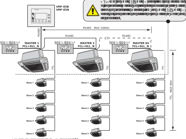
The individual or network master units are required to be combined with the VMF-E4 / VMF-E4D control panel
The Slave network units do not require the VMF-E4 / VMF-E4D control panel, they simply need to be connected (TTL) to the Master unit
Each network Master unit can have up to 5 Slave units connected to it
The Master network units can be connected to a VMF-E5B or VMF-E5N main interface panel to manage the system
VMF System control panel accessory (connected to the individual units or only to the Master units)
M ain interface panel Accessory to manage the VMF System network (connected to the Master units)
Accessory water temperature probe for a 2-pipe system
Accessories water temperature probes for a 4-pipe system
GLL10 (600x600) GLL20 (840x840)
Intake and delivery grille unit (obligatory accessory)
GLL10 - GLLI20 INTAKE AND DELIVERY GRILLE UNITunits are compulsory accessories as the
GLL10M INTAKE AND DELIVERY GRILLE UNIT WITH MOTORISED FINS GLL10M (600x600)
Intake and delivery grille unit with motorised fins and remote control (obligatory accessory)
GLL10R (600x600) GLL20R (840x840)
GLL10R - GLL20R INTAKE AND DELIVERY GRILLE UNIT
The GLL_N accessory consists of
GLL10N (600x600) GLL20N (840x840)
Intake and delivery grille unit with "VMF System" advanced electronic thermostat (obligatory accessory)
FCLMC10
FCLMC20
FCLMC SUCTION FLANGE
FCLMC10 FCLMC20
KFLD
KFL20 (***)
KFLD SUCTION FLANGE
KFL20
KFLD20
KFLD20 (***)
VHL2 - VHL22
Obligatory accessory for 4-pipe systems with variable flow rates
VHL2 - VHL22 2-WAY VALVES KIT
VHL1 - VHL20
Obligatory accessory for 4-pipe systems
SIT3
SIT3 - SIT5 INTERFACE CARDS
The electronic control panels or those with valve control must be interfaced with a SIT 5
The electromechanical control panels with just the speed control can be fitted directly to the SIT 3 without the SIT 5
RXLE RXLE20
This accessory can only be used with the FCL models fitted with GLL_M, GLL_R or GLL_N range grilles
SW4 WATER TEMPERATURE PROBE FOR
2-PIPE SYSTEMS
HOT WATER CIRCUIT IN 4-PIPE SYSTEMS SW4
SW3 MINIMUM WATER TEMPERATURE SENSOR
SWA MINIMUM WATER AND AIR TEMPERATURE PROBE
Wired control panel, user interface for thermostats built into GLL10N and GLL20N grid units, and for all other VMF thermostats. Supervisor-controlled operation mode (VMF-E5B / VMF-E5N) See the accessories manual for full information on this.
VMF-E4 / VMF-E4D
FCL + GLL10N FCL + GLL20N
VMF-E4
PANTONE COOL GRAY 1C
VMF-E4D
PANTONE 425C (METAL)
FCL+GLL_N
WARNING: The VMF-E5B / VMF-E5N panel allows management of the individual masters; The slave units connected to each master cannot be managed individually from the VMF-E5B / VMF-E5N panel, but they get the settings from the master they are connected to. Heat recovery units: Allow up to 3 per programmable recovery units based on timing and/or by metering.
See the accessories manual for complete information on its features
The most important feature is the possibility to manage the plant by means of dedicated algorithms to achieve a comfortable environment with energy saving in mind. Thermostat for fan coils installed in systems with 4 pipes, 2 pipes and 2 pipes with heater, with the possibility of connecting two On - Off valves to shut off the water feeding the coils.
See the accessories manual for complete information on its features
WMT10 CONTROL PANEL WITH ELECTROMECHANICAL THERMOSTAT
PX: control panel with selector
PX CONTROL PANEL WITH SPEED SELECTOR
ATTENTION: before carrying out any work, wear the appropriate individual
ATTENTION: The appliance must be installed in compliance with national
ATTENTION: the electric connections, the installation of the fan coils and
In particular, for the electric connec- tions, checks relative to the following
Measurement of the electric plant iso- lation resistance
Continuity test of the protection wires
ATTENTION: Install a device, master switch or electric plug that allows to
Do not install at height of above three metres
2-pipe system with resistance (Only for models and confi gu-
4-pipe system with resistance (Only for models and confi gu-
SYSTEM EXAMPLES
Choose where to install the machine according to the layout of the room, the number of units to be installed and any constraints imposed by the architecture. Remove the box, it is recommended to cut the corners of the box and remove the cardboard one by one. Operate the nut to adjust the height, finally check that the unit is installed in a horizontal position.
Run the hydraulic lines through the suspended ceiling to the mounting plate on the unit;. Vent the system, the vent valve for the two-pipe circuit is located externally on the connection plate. The vent valve for the heating circuit of the 4-pipe system is internal, remove the polystyrene tray to access it.
Instructions for mounting and connecting the electrical cabinet are in the manual that comes with the network accessories. After you have completed the connections and the electrical box is inserted into the housing in the FCL unit, secure it with two screws. ATTENTION: attach the safety cable to the screw terminal of the electrical box, which is located on the side of the hydraulic connections.
For GLL10M and GLL10R only: apply any air probe (SA) to the center of the fan grill, secure the cable with the supplied ties, lay the excess cable in the grooves made in the polystyrene. The grill frame should be positioned so that the AERMEC logo holder matches the corner of the electrical box. For GLL10M and GLL10R only: make the connections between the electrical box and the receiver.
Using the nuts, adjust the position of the unit against the support bracket so that the unit is level and the frame rests slightly on the suspended ceiling.
INSTALLATION IN PROXIMITY OF A WALL
Do not handle the unit using the hydraulic connections but use the
ATTENTION!! tighten the screws with maximum coupling torque
ATTENTION: fix a safety cable snap hook must then be attached to the grid
Disassembly for maintenance - Before performing any operation on
Electric box maintenance
In the 4-pipe version of the unit, it is mandatory to install the hot water coil valve accessory. For this purpose use the gaskets provided, the accessory has gaskets for connection to the system. Flow and return pipes must be equal, dimensioned and suitably insulated to avoid heat dissipation and dripping during operation in cooling mode.
CONDENSATE DRAIN CONNECTIONS During functioning in cooling mode the
The draining hole must always be closed again using the rubber cap
The electrical supply to the pump-float device must never be interrupted
SC = Condensate drain (male Ø 16mm)
CONNECTIONS FOR THE INTAKE OF EXTERNAL FRESH AIR
CONNECTION FOR THE AIR FLOW CONDITIONED IN AN ADJOINING ROOM
4) out(2) out
4) out (2) out
4) in Air out
The fan coils of the FCL cassette must be powered by 230V ~ 50Hz power and have a ground connection. The mains voltage must remain within the tolerance of ±10% in relation to the nominal value. The electrical power supply cable must be type H07 V-K or N07 V-K with 450/750V insulation if inside a pipe or raceway.
GLL10 GLL20
GLL10M - GLL10R - GLL20R - GLL10N - GLL20N
GLL10N - GLL20N
INSTALACIÓN Y SUSTITUCIÓN DEL FILTRO "Módul 600"
PERICOLO: Togliere tensione prima d’iniziare le operazioni di pulizia del filtro e/o dell’unità
DANGER: Switch off power supply before cleaning filter and/or unit
DANGER: Couper la tension avant de commencer les opérations de nettoyage du filtre et/ou de l'unité
GEFAHR: Vor der Reinigung des Filters und/oder des Gerätes die Strom versorgung abschalten
PELIGRO: Quitar la tensión antes de iniciar las operaciones de limpieza del filtro o de la unidad
PELIGRO: Apague la alimentación antes de comenzar a limpiar el filtro o la unidad.
INSTALACIÓN Y SUSTITUCIÓN DEL FILTRO "Módul 840"
KFLDKFL
FCL 36
IN OUT
IN OUT OUT
KFLD20 KFL20
FCL 102
Die Schaltpläne werden ständig aktualisiert, daher sollten Sie sich immer an dem Schaltplan orientieren, der dem Gerät beiliegt. AMP=Contatto alarme pump ràjo condensa Contact alarm entladung der kondensat pumpe Contact d'alarme de decharge de pompe. M = Morsettiera • Anschlussplatte Boitier • Anschlussplatte Placa de bornes DM = Motore aletta Louvre motor Moteur defl eteur Motorklappe Lamas motorizadas MP = Pompa ràjo condensa.
GND Erdungsanschluss Mise à terre Erdungsanschluss Toma de tierra RE = Resistenza elettrica RXLE Elektroheizung Resistance électrique Elt. Heizregister Resistencia eléctrica SA = Raumfühler Raumfühler Raumfühler Raumfühler Raumtemperaturfühler Raumfühler SC = Steuerungsschema. Die Schaltpläne werden ständig aktualisiert. Beachten Sie daher immer den dem Gerät beiliegenden Schaltplan.
GLL10 / GLL20
VHL1 / VHL2 + VHL20 / VHL22
RXLEGLL10M
VHL1 / VHL2 + RXLE
RXLEGLL10R / GLL20R
WMT10 + VHL1 / VHL2
PXAE
FMT10
GLL10 /GLL20
MARO
GLL10N / GLL20N
FCL_VL
SA LED
PXAE SIT3
AERMEC S.p.A