SPECIFICATIONS
Steering, Driving mechanism Inverter steering, Directly driven by motor Inverter steering, Directly driven by motor. External finish Pre-coated galvanized steel sheets (+powder coating for -BS . type) Pre-coated galvanized steel sheets (+powder coating for -BS type). Inverter circuit (COMP. / FAN) Overheat protection, Overcurrent protection Overheat protection, Overcurrent protection.
Heat exchanger Salt resistant cross fin & copper tube Salt resistant cross fin & copper tube. HIC circuit (HIC: Heat Inter-Changer) Copper tube, tube-in-tube structure Copper tube, tube-in-tube structure. Control , Drive Mechanism Inverter Control, Direct Driven by Motor Inverter Control, Direct Driven by Motor.
FAN Type x Quantity Propeller Fan x 1 Propeller Fan x 1 Propeller Fan x 1. Control , Drive Mechanism Inverter Control, Direct Driven by Motor Inverter Control, Direct Driven by Motor Inverter Control, Direct Driven by Motor. Compressor Type x Quantity Inverter scroll hermetic compressor Inverter scroll hermetic compressor Inverter scroll hermetic compressor Manufacture AC&R Works, MITSUBISHI ELECTRIC.
EXTERNAL DIMENSIONS
When the height of the front, rear or side walls
Build the foundation in such a way that the angle i. securely supported as shown in the right figure. Fig.A, B) When using a rubber insulating pad, please make sure that it is to cover the entire width of each of the unit's legs. The pipe section before the Twinning pipe (sections "a" and "b" in the figure) must have at least 500 mm of straight section (*including the straight pipe supplied with the twinning pipe).
Twinning pipe for liquid
CENTER OF GRAVITY
ELECTRICAL WIRING DIAGRAMS
SOUND LEVELS
CAPACITY TABLES
Based on the values of the nominal cooling/heating capacity and the ratios below, the capacity for different temperatures can be found. PUHY- RP850YSJM-B RP900YSJM-B (There is no difference in cooling performance between standard mode and COP priority mode.). The following tables can be used to find the maximum capacity to ensure that the system is installed with sufficient capacity for a given application.
Using the following correction factor according to the equivalent length of the pipes shown at 6-3-1 and 6-3-2, the capacitance can be observed. Equivalent length = (actual piping length to furthest indoor unit) + (0.35 x number of bends on the piping) [m]. Equivalent length = (actual piping length to furthest indoor unit) + (0.42 x number of bends on the piping) [m].
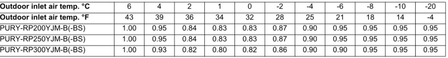
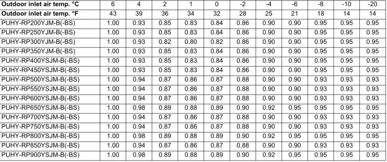
Equivalent length = (Actual pipe length to the farthest indoor unit ) + (0.50 x number of bends on the pipe) [m]. Due to frost at the outdoor heat exchanger and the automatic defrost operation, the heating capacity of the outdoor unit can be calculated by multiplying the correction factor shown in the table below.
OPTIONAL PARTS
UNIT SELECTION
If the distributed capacity of the indoor unit obtained in step 5) on the previous page is equal to or greater than the rated capacity of the indoor unit, the following formula will be used to calculate the capacity of the indoor unit: "Rated capacity x return air temperature correction factor x pipe length correction factor ( x pipe diameter correction factor)". The standard outside air temperatures used to obtain the return air temperature correction factor are 35ºCDB for cooling and 6ºCWB for heating. The heat load (13.5 kW/room), indoor unit return air temperature correction factor, and pipe length correction factor are used to calculate the required indoor unit capacity, based on which the model 125 indoor unit is tentatively selected.
The pipe length correction factor that can be obtained from the diagram for the system whose total indoor unit capacity is 250 would be 0.96. The correction factor for the return air temperature at 18.5ºCWB is 0.99 (at the standard outdoor dry bulb temperature of 35ºC), and this value can be inserted into the following formula to obtain the capacity. The cooling capacity of the tentatively selected outdoor unit divided by each indoor unit is 15.8 kW, which exceeds the rated cooling capacity of the model 125 unit (14.0 kW).
The heating capacity of the tentatively selected outdoor unit divided by each indoor unit is 16.8 kW, which exceeds the rated cooling capacity of the model 125 unit (16.0 kW). Pipe length: 50 m Capacity correction factor 0.99 (at standard indoor wet bulb temperature of 19ºC) Capacity correction factor: 0.97. The thermal load of 13 kW per room and the indoor unit return air temperature correction factor are used to calculate the required indoor unit capacity, based on which a model 125 indoor unit is selected in advance.
The result shows that the maximum capacity of the outdoor unit Qm (34.9 kW) exceeds the heating load Qi (29 kW). Capacity correction factor 0.99 (at standard indoor wet bulb temperature of 19ºC) Capacity correction factor: 0.97. Capacity correction factor 1.00 (at the standard indoor dry bulb temperature of 20ºC) Defrost correction factor is 0.975.
Calculate the total capacity of the indoor unit (N). calculations for both cooling and heating) Select the outdoor unit capacity (X). Correct the standard outdoor unit capacity (Qs) for the outdoor air temperature and the piping length to obtain the corrected capacity (Qm). In cases where indoor units from P100 to P140 are connected to only 1 port of BC controller (set BC controller DIP-SW 4-6 to OFF position), the cooling capacity of the indoor unit must be multiplied by a correction factor of 0 .97.
Refer to the correction factor chart for the outdoor unit whose capacity is closest to the system's total thermal load (Qi). Find the pipe length correction factor from the chart that corresponds to the total indoor unit capacity (N). If the thermal load exceeds the capacity of the indoor unit in one or more rooms, increase the size of the indoor unit as long as it does not exceed the maximum connection capacity of the outdoor unit.
Qm = Qs x Pipe length correction factor x Outdoor air temperature correction factor x Defrost correction factor (for heating only) x Pipe diameter correction factor.
Electrical work
Mains Wire Thickness, Switch Capacities and System Impedance Model Minimum Wire Thickness (mm2). When proceeding with wiring and connections, consider the environmental conditions (ambient temperature, direct sunlight, rainwater, etc.). Power cords for outdoor appliance parts shall not be lighter than polychloroprene sheathed flexible cord (Model 245 IEC57).
Be sure to use specified wires for connections and ensure that no external force is applied to terminal connections. Check the existing wires for insulation damage by measuring the resistance between the lead and ground with a 500V ohmmeter. This device is intended for connection to a power supply system with a maximum allowable system impedance shown in the above table at the interface point (power service box) of the user's supply.
The user must ensure that this device is only connected to a power supply system that meets the above requirements. If necessary, the user can ask the public power supply company for the system impedance at the interface point. This equipment complies with IEC, provided that the short-circuit power Ssc is greater than or equal to Ssc(*2) at the interface point between the user's supply and the public system.
It is the responsibility of the installer or user of the equipment to ensure, in consultation with the distribution network operator if necessary, that the equipment is only connected to a supply with a short circuit power Ssc greater than or equal to Ssc (*2).
M-NET control
Piping Design
Outdoor Installation
Caution for refrigerant leakage