Keep the operating instructions and other valid documents, such as the circuit diagram or motor instructions, with the multibox. Work on the electrical equipment of the fan may only be carried out by a qualified electrician or person with electrical training. Warranty for our products is based on the contractual terms, our quotations and also as a supplement to our General Business Terms and Conditions.
Multibox is suitable for conveying clean air, air with low dust and fat content, media up to the maximum. The maximum permissible operating data on the nameplate apply to an air density of 1.2 kg/m³ (sea level) and a max. 34; Pay attention to all defects in the connection cable, terminal box and rotor, cracks in the box, too.
34; Transport the fan either in the original packaging or on the supplied transport equipment (e.g. lifting lugs) with use. 34; When transporting by hand, consider acceptable human lifting or carrying capacity (see nameplate weight). EC technology is based on the optimal utilization of motors controlled by built-in electronics.
They lose less of their efficiency in part-load operation than asynchronous motors of the same power.
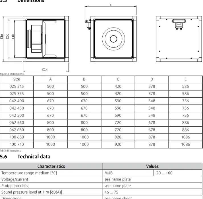
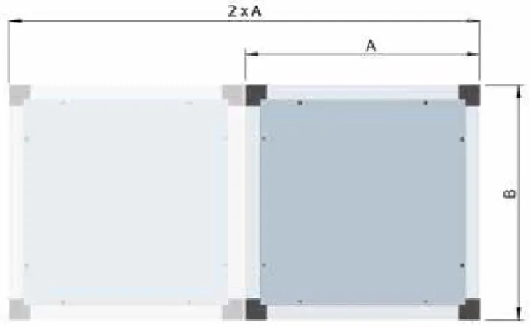
Dimensions
Technical data
Three-stage speed control as per EU Regulation 1253
Type key
MUB-CAV/VAV 025 315 EC
Motor data
Sensor-control module for differential pressure and volume PCA1000/6000D2
- General
- functionality constant air volume (CAV)
- functionality constant pressure - variable air controll (VAV)
- Volumenstrombestimmung für Einstromdüsen mit Druckentnahme
- constant pressure5.10.1 constant airflow
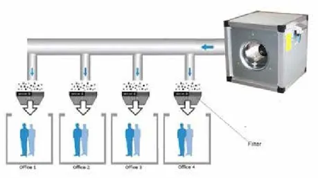
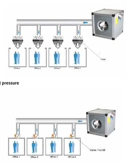
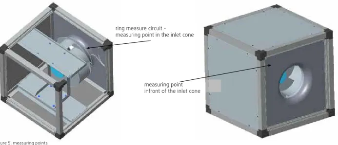
If the air volume (factory setting) is to be kept constant, the differential pressure in front of the inlet cone and in the inlet cone must be kept constant. If the pressure is to be kept constant in the duct system, the differential pressure between atmosphere and duct system must be kept constant. For this operating mode, the position of the measuring tubes must be changed with the "constant pressure set" (article no.: 75625).
The manual to change from CAV to VAV is included in the constant pressure kit. The volume of air can be calculated from the differential pressure. differential pressure between the measuring point in the inlet cone and in front of the inlet cone). If the air volume (factory setting) is constant, the differential pressure must be kept constant.
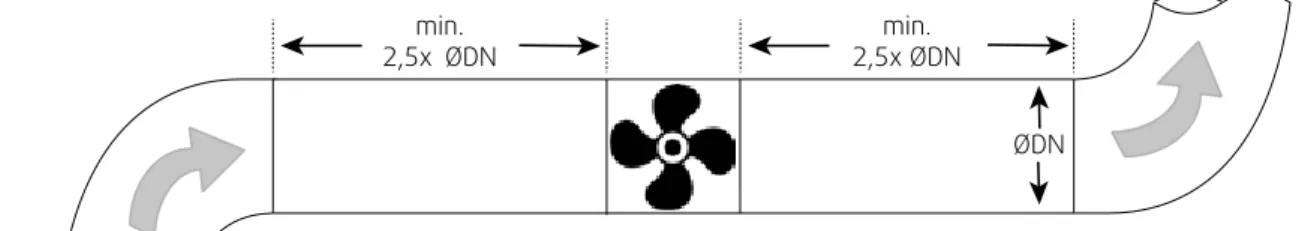
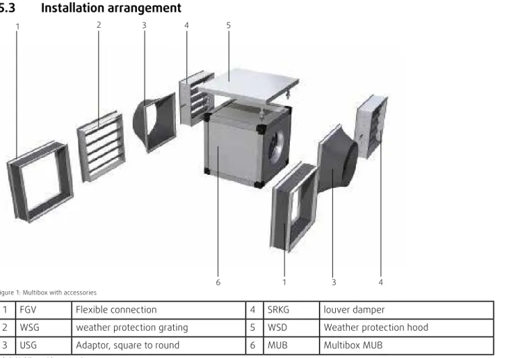
Installation
- Safety information
- Installation conditions
- Instructions for installation NOTE
NOTE
- Floor installation
- Wall or ceiling installation WARNING
- Shaft extensions CAUTION
- Steel shaft extension .1 Disassembly
- Rotor with screw-down hub made from aluminium or steel .1 Disassembly
- Rotor with taper clamping bush .1 Disassembly
- Electrical connection
- Safety information
- Cables
- Cablebushing panel
34; Seal the contact area between the base frame and the base or surface with foam tape or foam tape. The ball bearings of the motor and the counterweight rotor can be damaged by strong shocks in the assembly. Attach the rotor and/or shaft extension to the shaft or rotor without heavy impact.
The hub can be heated for easier assembly and disassembly, for example with a hot air blower. Tools: matching hex wrench and suitable tools for removal, torque wrench for the taper bushing. Attach the shaft extension so that the sleeve is over the shaft extension so that it can be fitted.
Tighten the two sleeve screws with a hex key so that they press against the shaft pin. 34; Punch the nominal breaking point in the aluminum hub and attach the removal tool there. Note that the mounting screws press against the flat side of the shaft extension if the shaft extension is small.
Drive a screw into the center of the three threaded holes and remove the collet from the shaft. Tighten the two screws evenly with the torque wrench with the tightening torque according to Tab. 34; Use only cables configured for the amperage according to the rating plate.
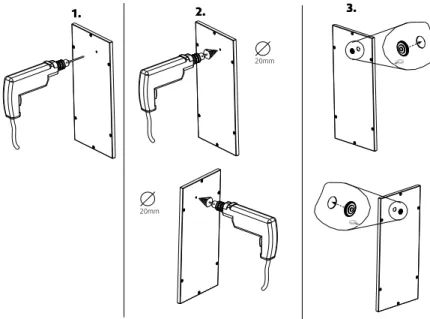
If a cable grommet is required through the panel, pay attention to the following notes and the instruction picture (Figure 8).
Vorsicht
Connection
You will find the electrical circuit diagram on the base plate of the motor or in the junction box. 34; Lay the connection cables in the junction box in such a way that the lid of the junction box can be closed. 34; Tighten the nuts of the cable ducts well to guarantee protection class IP.
34; Next, seal the cover screw connections on the plastic junction boxes (if used) with sealant.
CAUTION
- Mains deactivation if multiple devices are installed in parallel CAUTION
- Protecting the motor
- Earth wire transition resistance according to EN 61800 -5-1WARNING
- Residual current circuit breaker
- Commissioning
- Safety information
- Preconditions
- Notes
- Tests when activated
34; Avoid phase failures: If using 3-phase motors, use an all-pole C or K circuit breaker (see nameplate for current consumption). Observe the 5 electrical safety rules when performing any type of work on the engine (see section 2.5). Check compliance with the impedance specifications according to EN 61800-5-1 for the earth connection circuit in the final application.
Connect another protective earth wire via the additional connection point on the device, depending on the installation situation. 34; This prevents pulsating charging currents from the capacitors in the built-in EMC filter when. Material remaining from the installation and foreign objects are removed from the fan and ducts.
An EMC fi lter is integrated to meet the limit values for emitted interference and interference resistance. This means that reactive currents in the power supply line can still be measured even though the motor is stationary and the power supply is activated. Due to the locked rotor protection, the inrush current (LRA) is equal to or less than the rated current (FLA).
WARNING
- Checking the safety elements
- Check that safety elements and protective grilles are securely fastened
- Switching the device on
- Switching the device off
- Switching the device off during operation
- Switching the device off for maintenance work WARNING
- Operation
- Safety information
- Operating conditions
- Integrated protective function NOTE
- Operation/use
- Switching the device off
- Switching the device on
- Troubleshooting/maintenance/repair
- Safety information
- Switching the device off for maintenance work
- Preconditions
- Faults and troubleshooting
- Switching the device on
- Maintenance/repair .1 Replacing the bearings
- Spare parts WARNING
- Cleaning
- Safety information
- Switching the device off WARNING
- Procedure Note
- Switching the device on
- Uninstalling/disassembly
- Safety information
- Disconnecting
- Disassembly
34; Before switching on the device, check the device for external visible damage and make sure that the protective. The integrated protective functions ensure that the motor switches off automatically in the event of any of the faults described in the table. 34; Use the Multibox only in accordance with these instructions for use and the instructions for use of the.
Fan air output too low Incorrect direction of rotation of rotor Contact the manufacturer Excessive pressure loss in the lines Change the wiring Flow regulators not or only partially open Check opening position on site Intake or pressure channels are blocked Remove the blocks. The temperature monitoring has responded Let the engine cool down, find and remedy the cause of the error, release the reactivation lock if necessary. 34; Please contact the manufacturer's customer service in case of any kind of damage, e.g.
Use a voltage that corresponds to the peak value of the AC voltage required in the standard. The interior of the Multibox may only be cleaned by a trained electrician or trained and trained specialist personnel. The device may only be switched off and uninstalled by a trained electrician or trained and trained qualified personnel.
13 Disposal
Disposal of the fan .1 Safety information
- Final disassembly and disposal
When selecting the lifting equipment and fitting material, pay attention to the weight, tendency to vibrate and shear forces (weight information on the nameplate).