Manuale d’installazione User manual
humidifi ers for steam baths
umidifi catori per bagni turchi
WARNINGS
The CAREL S.p.A. humidifi ers are advanced products, whose operation is specifi ed in the technical documentation supplied with the product or can be downloaded, even prior to purchase, from the website www .carel. com. Each CAREL S.p.A. product, in relation to its advanced level of technology, requires setup/confi guration/programming/commissioning to be able to operate in the best possible way for the specifi c application. The failure to complete such operations, which are required/indicated in the user manual, may cause the fi nal product to malfunction; CAREL S.p.A. accepts no liability in such cases.
The customer (manufacturer, developer or installer of the fi nal equipment) accepts all liability and risk relating to the confi guration of the product in order to reach the expected results in relation to the specifi c fi nal installation and/or equipment. CAREL S.p.A. may, based on specifi c agreements, acts as a consultant for the installation/commissioning/use of the unit, however in no case does it accept liability for the correct operation of the humidifi er and the fi nal installation if the warnings or suggestions provided in this manual or in other product technical documents are not heeded. In addition to observing the above warnings and suggestions, the following warnings must be heeded for the correct use of the product:
DANGER OF ELECTRIC SHOCK
The humidifi er contains live electrical components. Disconnect the mains power supply before accessing inside parts or during maintenance and installation.
DANGER OF WATER LEAKS
The humidifi er automatically and constantly fi lls/drains certain quantities of water. Malfunctions in the connections or in the humidifi er may cause leaks.
DANGER OF BURNS
The humidifi er contains high temperature components and delivers steam at 100°C/ 212°F.
Important Important:
The installation of the product must include an earth connection, using the special yellow-green terminal available in the humidifi er.
The environmental and power supply conditions must conform to the values specifi ed on the product rating labels.
The product is designed exclusively to humidify rooms either directly or through distribution systems (ducts).
Only qualifi ed personnel who are aware of the necessary precautions and able to perform the required operations correctly may install, operate or carry out technical service on the product.
Only water with the characteristics indicated in this manual must be used for steam production.
All operations on the product must be carried out according to the instructions provided in this manual and on the labels applied to the product. Any uses or modifi cations that are not authorised by the manufacturer are considered improper. CAREL S.p.A. declines all liability for any such unauthorised use.
Do not attempt to open the humidifi er in ways other than those specifi ed in the manual.
Observe the standards in force in the place where the humidifi er is installed.
Keep the humidifi er out of the reach of children and animals.
Do not install and use the product near objects that may be damaged when in contact with water (or condensate). CAREL S.p.A. declines all liability for direct or indirect damage following water leaks from the humidifi er.
Do not use corrosive chemicals, solvents or aggressive detergents to clean the inside and outside parts of the humidifi er, unless specifi cally indicated in the user manual.
Do not drop, hit or shake the humidifi er, as the inside parts and the linings may be irreparably damaged.
CAREL S.p.A. adopts a policy of continual development. Consequently, CAREL reserves the right to make changes and improvements to any product described in this document without prior warning. The technical specifi cations shown in the manual may be changed without prior warning.
The liability of CAREL S.p.A. in relation to its products is specifi ed in the CAREL S.p.A. general contract conditions, available on the website www . carel. com and/or by specifi c agreements with customers; specifi cally, to the
•
•
•
•
•
•
•
•
•
•
•
•
•
•
•
exemplary, special or consequential damage of any kind whatsoever, whether contractual, extra-contractual or due to negligence, or any other liabilities deriving from the installation, use or impossibility to use the product, even if CAREL S.p.A. or its subsidiaries are warned of the possibility of such damage.
DISPOSAL
The humidifi er is made up of metal parts and plastic parts. In reference to European Union directive 2002/96/EC issued on 27 January 2003 and the related national legislation, please note that:
WEEE cannot be disposed of as municipal waste and such waste must be collected and disposed of separately;
the public or private waste collection systems defi ned by local legislation must be used. In addition, the equipment can be returned to the distributor at the end of its working life when buying new equipment;
the equipment may contain hazardous substances: the improper use or incorrect disposal of such may have negative eff ects on human health and on the environment;
the symbol (crossed-out wheeled bin) shown on the product or on the packaging and on the instruction sheet indicates that the equipment has been introduced onto the market after 13 August 2005 and that it must be disposed of separately;
in the event of illegal disposal of electrical and electronic waste, the penalties are specifi ed by local waste disposal legislation.
Warranty on the materials: 2 years (from the date of production, excluding consumables).
Approval: the quality and safety of CAREL S.P.A. products are guaranteed by the ISO 9001 certifi ed design and production system, as well as by the mark.
1.
2.
3.
4.
5.
Content
1. INTRODUCTION AND ASSEMBLY 7
1.1 humiSteam Wellness (UEW*) ... 7
1.2 Dimensions and weights ... 7
1.3 Opening the packaging ... 7
1.4 Positioning on the wall ... 7
1.5 Wall-mounting... 7
1.6 Removing the front cover ... 8
1.7 Fitting the front cover ... 8
1.8 Components and accessories ... 9
2. WATER CONNECTIONS 10
2.1 Supply water ... 112.2 Drain water ... 11
3. STEAM DISTRIBUTION 12
3.1 CAREL jet distributors (SDPOEM00**) ... 123.2 CAREL linear distributors (DP***DR0) ... 12
3.3 Steam hose ... 12
3.4 Condensate drain hose ... 13
4. ELECTRICAL CONNECTIONS 14
4.1 Preparing the electric cableways ... 144.2 Power cable connection ... 14
4.3 Temperature probe connection (M2.1- M2.8) ... 14
4.5 Alarm contact (M6.1 - M6.3) ... 15
4.6 Utility connections (light, fans, sanitisation, essences) ... 15
5. REMOTE TERMINAL, GSM MODEM AND SUPERVISORY NETWORK 17
5.1 Remote display terminal ...175.2 GSM network connection (send SMS) ...17
5.3 Supervisory network (J19) ...17
6. STARTING AND USER INTERFACE 18
6.1 Starting ... 186.2 Stopping ... 18
6.3 User interface ... 18
6.4 Management menu ... 19
7. MAIN CONFIGURATIONS 21
7.1 Language ... 217.2 Date and time ... 21
7.3 Temperature probes ... 21
7.4 Essences ... 21
7.5 Time bands ...22
7.6 Fans ...22
7.7 Sanitisation ...23
7.8 Advanced settings (qualifi ed personnel only) ...23
7.9 Copying the settings (backup) ...24
7.10 GSM (send SMS on alarms) ...25
7.11 Enable supervisor network ...25
7.12 Manual procedures (qualifi ed personnel only) ...25
7.13 Displaying the alarms ...26
7.14 Info-menu ...27
7.15 Mechanically draining the water in the cylinder ...27
8. MAINTENANCE AND SPARE PARTS 28
8.1 Spare parts for models UE001 to UE018 ...288.2 Spare parts, models UE025 to UE065 ...30
8.3 Cleaning and maintenance of the cylinder ...32
8.4 Cylinder connection, three-phase models UE025 to UE065 ...32
8.5 Cleaning and maintenance of the other components ...32
9. WIRING DIAGRAMS 33
9.1 Diagram of single-phase models UE001 to UE009 ...339.2 Diagram of three-phase models UE003 to UE018 ...34
9.3 Diagram of three-phase models UE025 to UE065 ...35
10. CARATTERISTICHE GENERALI E MODELLI 36
10.1 humiSteam Wellness models and electrical specifi cations ...3610.2 Technical specifi cations ... 37
10.3 Models of steam hoses ... 37
10.4 Models of concentrated jet steam distributors ...38
10.5 Models of linear distributors ...38
installer user ser vic e 1. INTRODUCTION AND ASSEMBLY
1.1 humiSteam Wellness (UEW*)
Range of CAREL isothermal immersed electrode humidifi ers with liquid crystal display for the control and distribution of steam in steam baths.
Models available (identifi able from the code shown on the product):
UE001, UE003, UE005, UE008, UE009, UE010, UE015, UE018: smaller models with steam production capacity up to 18 kg/h, water connections under the base of the humidifi er;
UE025, UE035, UE045, UE065: larger models with steam production capacity from 25 to 65 kg/h, water connections on the side of the humidifi er.
1.2 Dimensions and weights
Models UE001 to UE018 Models UE025 to UE065
Fig. 1.a
UE001…
UE008
UE009…
UE018
UE025…
UE045
UE045**…
UE065 dimensions
(mm)
A 365 365 545 635
B 275 275 375 465
C 620 712 815 890
weights (kg)
packaged 16 20 39 51
empty 13.5 17 34 44
installed* 19 27 60.5 94
Table 1.a
*= in operating conditions fi lled with water;
**= 230 Vac model
1.3 Opening the packaging
make sure the humidifi er is intact upon delivery and immediately notify the transporter, in writing, of any damage that may be due to careless or improper transport;
move the humidifi er to the site of installation before removing from the packaging, grasping the neck only from underneath the base;
open the cardboard box, remove the protective material and remove the humidifi er, keeping it vertical at all times.
1.4 Positioning on the wall
the unit is designed to be mounted on a wall that is strong enough to support the weight in normal operating conditions (see Wall-mounting below). Models UE025 to UE065 can stand on the fl oor;
to ensure correct steam distribution, position the humidifi er near the point of steam distribution;
make sure the humidifi er is level, allowing the minimum clearances (see Fig. 1.b) for maintenance operations.
Important
Important: during operation the metal casing heats up and the
•
•
o
o o
•
•
•
Distance from the walls
Models UE001 to UE018 Models UE025 to UE065
Fig. 1.b
1.5 Wall-mounting
Fit the humidifi er on the wall using the support bracket and the screw kit supplied (for the dimensions in mm see Fig. 1.d).
Assembly instructions:
unscrew the wall bracket from the humidifi er bracket;
fasten the wall bracket (see Fig. 1.c), checking horizontal position with a spirit level; if installed on a masonry wall, the plastic anchor plugs (dia. 8 mm) and screws (dia. 5 mm x L= 50 mm) supplied can be used;
hang the appliance to the bracket using the slot on the top edge of the rear of the appliance;
secure the appliance to the wall through the hole in the centre on the rear of the unit. For the weights and dimensions see Tab.1.a.
Models UE001 to UE018
X
bracket
Models UE025 to UE065
X
bracket
Fig. 1.c 1.
2.
3.
4.
installer user ser vic e
Spacing of the holes on the wall
Models UE001 to UE018 Models UE025 to UE065
= X
Y
X
Y
Z
= =
= =
=
Fig. 1.d
distance (mm)
Models
UE001…UE018 UE025…UE045 UE045*…UE065
X 270 310 400
Y 360 655 730
Z - 250 315
* 230 Vac models only
1.6 Removing the front cover
Models UE001 to UE018:
1 2
4 3 5
Fig. 1.e
turn oval-shaped label with the Carel logo, revealing the head of the earth screw below;
remove the screw using a screwdriver;
hold the cover by the sides and lift it around 200 mm, releasing it from the protruding edges of the humidifi er;
remove the cover by moving it forwards;
remove the protective fi lm.
1.
2.
3.
4.
5.
Modelli UE025…UE065:
1
3 2 4
Fig. 1.f
remove the screws from the top of the humidifi er using a screwdriver;
hold the cover from the top and lift it around 200 mm;
remove the cover by moving it forwards;
remove the protective fi lm (from all the outside surfaces of the humidifi er).
1.7 Fitting the front cover
Models UE001 to UE018:
1
3 4
2
Fig. 1.g
turn the red oval-shaped plate with the CAREL logo, revealing the fastening hole below;
slip the cover onto the frame (keeping it slightly raised and tilted), until it rests on the rear edges;
tighten the earth screw using a screwdriver;
turn the red oval-shaped plate with the CAREL logo until covering the fastening holes.
1.
2.
3.
4.
1.
2.
3.
4.
installer user ser vic e
Models UE025 to UE065:
1 2
Fig. 1.h
slip the cover onto the frame (keeping it slightly raised and tilted), until it rests on the rear edges;
tighten the screws on the top of the humidifi er using a screwdriver.
Important
Important: in models UE025 to UE065 open the electrical compartment on the humidifi er using the lock with slot.
Fig. 1.i 1.
2.
1.8 Components and accessories
Once having opened the packaging and removed the front cover of the humidifi er, make sure the following are included:
kit of screws with plugs for wall-mounting;
o kit code 98C565P009 of
connectors for the electronic board
o
kit code 98C565P012 of connector with label and cable gland for the connection of the utility cables (light, fans, essences and sanitisation pump)
o fi lter code 98C565P016 for fi ll
solenoid valve o
kit code 98C565P018 of connectors for terminals with voltage-free contacts
o models UE025 to UE065 only:
code FWHDCV0000 non- return valve with connection pipe
o
UE025 to UE065 only: angular plastic hose (drain water connection).
o
installer user ser vic e
2. WATER CONNECTIONS
Important: before proceeding, disconnect the power supply.
Models UE001 to UE018 Models UE025 to UE065
Fig. 2.a
Water connections:
o 1. install a manual valve upstream of the installation (to be able to cut off the water supply);
o 2. connect the humidifi er to the water supply, and fi t the fi lter supplied (code 98C565P016) to the inlet of the fi ll solenoid valve.. On models UE001 to UE0018, use a hose with 3/4’’G fi ttings (see par. “10.2 Technical specifi cations” page 37, compatible CAREL hose: code FWH3415000). On models UE025 to UE065 connect the hose with the non-return valve supplied (code FWHDCV0000) to prevent the water inside the humidifi er from coming into contact with the mains water;
o 3. install a mechanical fi lter to trap any solid impurities (to be connected downstream of the tap);
o 4 connect a section of non-conductive pipe or hose for draining (resistant to temperatures of 100 °C and with a minimum inside diameter of 40 mm);
o 5 prepare a funnel to interrupt continuity in the drain line;
o 6 connect a drain trap to prevent the return of bad odours (minimum inside diameter 40 mm);
o 7 in models UE025 to UE065: connect a drain hose from the bottom tank of the humidifi er (this can run into the drain funnel).
Important
Important: when installation is completed, fl ush the supply hose for around 30 minutes by piping water directly into the drain, without sending it into the humidifi er. This will eliminate any scale or processing residues that may block the drain pump and cause foam when boiling.
Fittings provided for the water connections:
Models UE001 to UE018 Models UE025 to UE065
Key:
A. supply water inlet B. drain water outlet
C. bottom tank drain water outlet (models UE025 to UE065 only)
Fig. 2.b
installer user ser vic e
2.1 Supply water
Only use mains water with:
pressure between 0.1 and 0.8 MPa (1 and 8 bars), temperature between 1 and 40 °C and an instant fl ow-rate no lower than the rated fl ow of the fi ll solenoid valve, the connection is G3/4M (see par. “10.2 Technical specifi cations” page 37);
hardness no greater than 40°fH (equal to 400 ppm of CaCO3), conductivity: 125 to 1250 μS/cm;
no organic compounds.
supply water characteristics
unit of measure
normal water
water with low salt content min. max. min. max.
Hydrogen ions (pH) 7 8.5 7 8.5
Specifi c conductivity at 20°C (σR, 20 °C)
μS/cm 350 1250 125 350
Total dissolved solids (cR) mg/l (1) (1) (1) (1) Dry residue at 180°C (R180) mg/l (1) (1) (1) (1) Total hardness (TH) mg/l CaCO3 100 (2) 400 50 (2) 160 Temporary hardness mg/l CaCO3 60 (3) 300 30 (3) 100
Iron + Manganese mg/l Fe+Mn = 0.2 = 0.2
Chlorides ppm Cl = 30 = 20
Silica mg/l SiO2 = 20 = 20
Residual chlorine mg/l Cl- = 0.2 = 0.2
Calcium sulphate mg/l CaSO4 = 100 = 60
Metallic impurities mg/l 0 0 0 0
Solvents, thinners, detergents, lubricants
mg/l 0 0 0 0
Tab. 3.a
(1)= values depend on the specifi c conductivity; in general:
CR≅0.65 * σR, 20 °C; R180≅0.93 * σR, 20 °C
(2) = not less than 200% of the chloride content in mg/l CL
(3) = not less than 300% of the chloride content in mg/l CL-
There is not reliable relationship between hardness and conductivity of the water
Important:
Important:
do not treat the water with softeners, this may cause the entrainment of foam, aff ecting the operation of the unit;
do not add disinfectants or anticorrosive compounds to the water, as these are potential irritants;
the use of well water, industrial water or water from cooling circuits and, in general, any potentially chemically or bacteriologically contaminated water is not recommended.
2.2 Drain water
this contains the same substances dissolved in the supply water, however in larger quantities;
it may reach a temperature of 100 °C;
it is not toxic and can be drained into the sewerage system.
•
•
•
•
•
•
•
•
•
installer user ser vic e
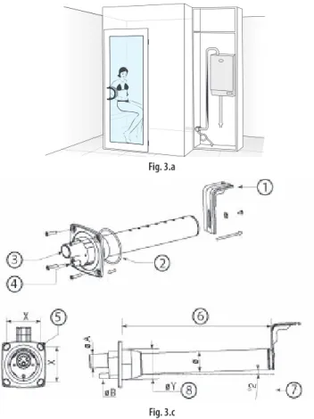
3. STEAM DISTRIBUTION
For the correct delivery of steam, a steam distributor must be used, sized according to output of the humidifi er.
In addition, the distributor must be installed in a part of the steam bath that is easily reached by the hoses running from the humidifi er (see Fig.
3.a as an installation example).
3.1 CAREL jet distributors (SDPOEM00**)
These can be fi tted horizontally or vertically (hole facing upwards).
See par. “10.4” page 38 for the models of distributors that are compatible with the humidifi ers.
Assembly instructions (see Fig.3.b):
make a series of holes on the wall according to the distributor drilling template;
insert the distributor;
fasten the fl ange using 4 screws.
Fig. 3.b Key:
A. steam inlet B. condensate drain C. steam outlet.
the dimensions of the hole vary depending on the models of distributor:
model SDPOEM0000: hole made manually, up to 30 mm in diameter);
model SDPOEM0012: diameter of the hole 12 mm;
model SDPOEM0022: diameter of the hole 22 mm.
D drilling template
Note: if steam hoses with an inside diameter of 30 mm are used, remove the 22 mm steam inlet section.
3.2 CAREL linear distributors (DP***DR0)
These can be fi tted horizontally. See par. “10.5” page 38 for the models of distributors that are compatible with the humidifi ers.
Assembly instructions (see Fig.3.c):
make a series of holes on the wall according to the distributor drilling template (included in the packaging with the distributor);
insert the distributor with the steam holes facing upward;
fasten the fl ange using 4 screws.
•
•
•
•
•
•
Fig. 3.a
Fig. 3.c Key:
1 “L”-shaped mounting support (where featured) 2 fl ange gasket
3 steam inlet (ØA) 4 condensate drain (ØB)
5 fastening screws (see the instruction sheet supplied with the distributor)
6 length (depending on the model of distributor, see par. “10.5” page 38) 7 angle (around 2°) for draining the condensate.
8 diameter of the hole on the wall (ØY) Dimensions in mm
CAREL linear distributors DP***D22R0 DP***D30R0 DP***D40R0
ØA 22 30 40
ØB 10 10 10
ØY 58 68 89
Ø 35 45 60
X 68 77 99
Tab. 3.a Important:
Important:
fi t the distributor at a slight incline (at least 2°, to prevent the return of condensate);
the “L”-shaped mounting support (see part 1 Fig. 3.c) is supplied with steam distributor models from DP085* to DP025*. For shorter lengths, the support can be supplied as an option (code 18C478A088).
3.3 Steam hose
use CAREL hoses (max. 4 m long, see par. “10.3” page 37). Rigid pipes may break and cause steam leaks;
avoid the formation of pockets or traps (causes of condensate);
avoid choking the hose due to tight bends or twisting.
fasten the end of the hose to the connectors on the humidifi er and the steam distributor using metal clamps, so that these do not detach due to the high temperature.
1.
2.
•
•
•
•
installer user ser vic e
3.4 Condensate drain hose
During the operation of the humidifi er some of the steam may condense, causing a decline in effi ciency and noise (gurgling).
To drain the condensate, connect a drain hose with a drain trap and a minimum slope of 5° to the bottom of the humidifi er (see Fig. 3.d). CAREL condensate drain hoses: code 1312353APG
Important
Important: the drain trap in the condensate drain hose the humidifi er must be fi lled with water before starting.
Example of correct and incorrect installation of the steam hose and condensate drain hose:
YES
NO
NONO
Fig. 3.d
Verifi che fi nali
the steam outlet hoses run upwards and the distributor has a minimum incline of 2° upwards (see Fig. 3.c);
the ends of the hose are tightened to the fi ttings with metal clamps;
the curves in the tubing are suffi ciently wide (radius > 300 mm) so as to not cause bending or choking;
the steam hose has no pockets or traps for condensate to form;
the paths of the steam and condensate hoses are as described in this chapter (see Fig. 3.d);
the length of the steam hose is no greater than 4 metres;
the incline of the steam hose is suffi cient to allow correct draining of the condensate (> 20° for the upward sections, > 5° for the downward sections);
the incline of the condensate hose is at least 5° at every point;
the condensate hose always follows a downwards path and features a drain trap (fi lled with water before starting operation) to avoid steam being released.
o o o o o o o
o o
installer user ser vic e
4. ELECTRICAL CONNECTIONS
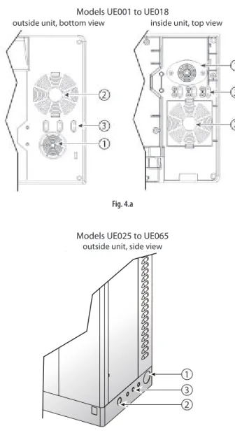
4.1 Preparing the electric cableways
Models UE001 to UE018
outside unit, bottom view inside unit, top view
Fig. 4.a
Models UE025 to UE065 outside unit, side view
3 2 1
Fig. 4.b Key to Figs. 4.a and 4.b:
1. power cable inlet;
2. utility cable inlet (after having drilled the plastic part): sanitisation pump, essences, fans, light.
3. probe cable inlet. On models UE001 to UE018, remove the plastic “tab”
and use it to secure the cable (held in place by the screws provided).
4.2 Power cable connection
Single-phase models Three-phase models
humiSteam Wellness
AP2AP1 GND L N
humiSteam Wellness
AP2AP1 GND L1 L2 L3
Fig. 4.c (view inside unit, electrical compartment) Important
Important: connect the yellow-green cable to the earth point (GND).
4.3 Temperature probe connection (M2.1- M2.8)
the humidifi er can be connected to up to two probes for measuring and controlling the temperature inside the steam bath. The connection with two probes allows an “average” temperature reading (with the possibility to attribute a diff erent “weight” to each probe, see par. “7.3 Temperature probes”, page 21);
active probes (voltage or current signal, CAREL code: ASET030001) or NTC probes (variable resistance) can be connected.
For connection, use the “eight pin” connection kit (supplied in the packaging) and run the cables out of the humidifi er through the “cable opening” (Figs. 4.a or 4.b).
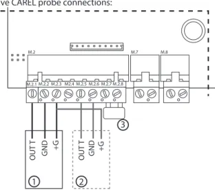
Active CAREL probe connections:
OUT T GND +G OUT T GND +G
1 2
3
M.2 M.7 M.8
M.2.1 M.2.2 M.2.3 M2.4 M.2.5 M.2.6 M.2.7 M.2.8
Fig. 4.d (detail of electronic board, humidifi er electrical compartment)
•
•
installer user ser vic e
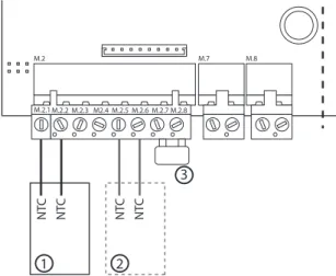
CAREL NTC probe connections:
NTC NTC NTC NTC
1 2
3
M.2 M.7 M.8
M.2.1 M.2.2 M.2.3 M2.4 M.2.5 M.2.6 M.2.7 M.2.8
Fig. 4.e (detail of electronic board, humidifi er electrical compartment)
Key to Figs. 4.d and 4.e:
1 probe CAREL 1
2 CAREL probe 2 (if available)
3 remote ON/OFF (contact closed= humidifi er enabled; contact open=
humidifi er disabled, in standby)
If non-CAREL probes are used, check:
voltage signal: 0 to 1 Vdc, 0 to 10 Vdc, 2 to 10 Vdc, terminal M2.1 (GND:
M2.2);
current signal: 4 to 20, 0 to 20 mA, terminal M2.4 (GND: M2.6).
In addition, depending on the type of power supply:
+15 V, terminal M2.3;
+ 1 Vdc 135 ohm, terminal M2.4.
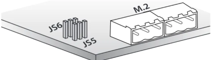
Input probe confi guration (pin strip connectors JS5, JS6)
JS5
M.2 JS6
Fig. 4.f (detail of electronic board, in the humidifi er electrical compartment)
pin strip confi guration position 0 to 10 Vdc
2 to 10Vdc
0 to 1 Vdc, 4 to 20/0 to 20 mA, NTC probes
JS5 probe 1
basic confi guration
JS6 probe 2
basic confi guration Important:
to avoid unbalanced control, the earth of the probes or the external control devices must be connected to the earth of the appliance’s controller.
For the operation of the humidifi er, M2.7 and M2.8 must be connected to the “remote ON/OFF” via an enabling contact or alternatively jumpered (default solution). If these terminals are not connected, all the internal and external devices managed by the controller will be disabled, with the exception of the drain pump for emptying the unit after extended periods.
•
•
•
•
•
•
Note: in industrial environments (IEC EN61000-6-2), the cables leaving the unit must not exceed 30 m in length, except for the room probe (terminals M2 pin 1-2-3-4-5-6), the remote on/off digital input (terminal M2 pin 7-8) and cable shields for RS485 communication.
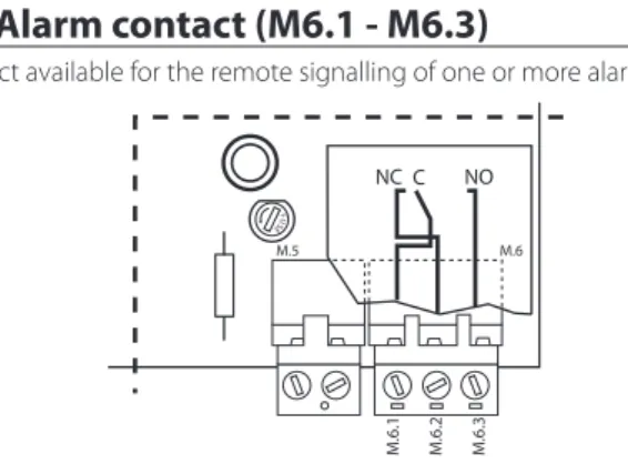
4.5 Alarm contact (M6.1 - M6.3)
Contact available for the remote signalling of one or more alarms.
M.5 M.6
M.6.1 M.6.2 M.6.3
NC C NO
FUSE
Fig. 4.g (detail of utilities board, humidifi er electrical compartment) Electrical specifi cations: 250 Vac; Imax: 2 A resistive 2 A inductive.
Note: use clamps on the signal terminal blocks (alarm, utilities) to prevent the cables from being detached.
4.6 Utility connections (light, fans, sanitisation, essences)
The humidifi er features of a terminal block for connecting the utilities, located under the electronic board (see the following fi gure for the connections).
Depending on the type of connection, the required voltage is made available for the outputs to the utilities (12 V, 24 V, 230 V or voltage-free contact).
A B C D E F G
L+ L- VI+ VI- VE+ VE- P1+ P1-P2-P2+PS PS P3+ P3-
Fig. 4.h (detail of utilities board, humidifi er electrical compartment) Legenda:
A light (L+ L-);
B supply fan (VI+ VI-);
C exhaust fan (VE+ VE-);
D sanitisation pump (PS PS);
E essence pump 3 (P3+ P3-);
F essence pump 2 (P2+ P2-);
G essence pump 1 (P1+ P1-).
installer user ser vic e
♦ “Utilities powered at diff erent voltages”
The humidifi er activates but does not supply power to the utilities. The utilities are thus powered externally and at diff erent voltages.
Procedure:
remove the terminal block (2 pieces) from connector B and disconnect the L, N cables;
Insert the terminal block supplied (code 98C565P018) into connector B and reconnect the cables, L (terminal 1) & N (terminal 8);
jumper terminals AP1 and AP2;
insert the terminal block supplied (code 98C565P012) into connector A and connect the utilities (see the following fi gure).
Note:
maximum load for each utility: 2 A;
AP1 and AP2 are protected by 6.3 A fuses;
the utilities must be suitably protected against overloads and short- circuits.
1 2 3 4 5 6 7 8 9 10 11 12 13 14
L + L - V E -V I + V I - V E+ P 1+ P 1 -PS P 3+ P 3 - P 2+ P 2 -PS
to pCOe from pCOe
AP1 AP2
1
A B
3
2
external power supply
Fig. 4.j
Final checks
the rated voltage of the appliance corresponds to the rated supply voltage;
the fuses installed are suitable for the line and the power supply voltage;
a mains disconnect switch has been installed to disconnect power to the humidifi er when required;
the humidifi er has been correctly earthed;
the power cable is fastened using the tear-proof cable gland;
terminals M2.7 and M2.8 are connected by jumper or connected to an enable-operation contact;
if non-CAREL probes are used: the earth of the probes is electrically connected to the humidifi er board earth;
if the humidifi er is controlled by an external control device, the earth of the signal is electrically connected to the controller earth.
1.
2.
3.
•
•
•
o o o o o o o o
Types of utility connection
♦ “Utilities powered at the same voltage”
The humidifi er supplies power to and activates the utilities connected at the same voltage. This is done by applying a 12 V, 24 V or 230 V power supply to terminals AP1 and AP2.
Procedure:
insert the terminal block supplied (code 98C565P012) into connector A and connect the utilities (see the following fi gure).
Note:
maximum load for each utility: 2 A;
AP1 and AP2 are protected by 6.3 A fuses.
1 2 3 4 5 6 7 8 9 10 11 12 13 14
L + L - V E -V I + V I - V E+ P 1+ P 1 -PS P 3+ P 3 - P 2+ P 2 -PS
to pCOe from pCOe
AP1 AP2
12/24/230 Vac Imax= 6 A
A B
Fig. 4.i
•
•
installer user ser vic e 5. REMOTE TERMINAL, GSM MODEM AND SUPERVISORY NETWORK
5.1 Remote display terminal
The display terminal can be detached from the humidifi er and moved to another place.
Depending on the distance required, the following are necessary:
up to 50 metres: 6-wire telephone cable and two ferrites (code 0907858AXX) (see Fig. 5.a);
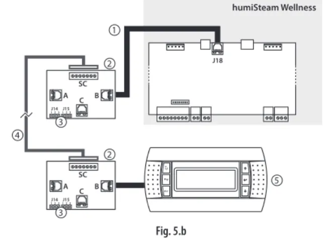
up to 200 metres: two CAREL TCONN6J000 boards, 6-wire telephone cables and an AWG20-22 shielded cable with 3 twisted pairs (for the connection of the two boards, Fig. 5.b).
Note: to fi ll the empty space left by the display terminal on the humidifi er, use CAREL kit code HCTREW0000.
Remote connection of the terminal up to max 50 m
J18
humiSteam Wellness
3 2
1
2
Fig. 5.a Key:
1 telephone cable (up to 50 m distance);
2 two ferrites (code 0907858AXX) to be applied to the ends of the telephone cable;
3 remote display terminal.
Remote connection of the terminal up to 200 m
J18
humiSteam Wellness
4
2
2
A
J14 1 2 3 1 2 3J15
C B SC A
J14 1 2 3 1 2 3J15
C B SC
5 3
3
1
Fig. 5.b Key:
1 telephone cable (up to 0.8 m distance);
2 CAREL TCONN6J000 board;
3 pin strip J14 and J15 in position 1-2 (power supply available on the telephone connectors A, B and C and screw SC);
4 AWG20-22 shielded cable with 3 twisted pairs to move the display terminal up to 200 m away. Connection to the TCONN6J00 board:
terminal SC function
0 EARTH (shield)
1 +VRL
2 GND
3 RX/TX-
4 RX/TX+
5 GND
6 +VRL
5 remote display terminal
•
•
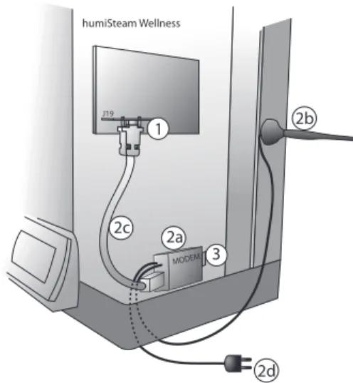
5.2 GSM network connection (send SMS)
The humidifi er can be confi gured to send SMS message for alarms and malfunctions (see par. “7.10”, page 25).
humiSteam Wellness
J19
1
2c
MODEM 3 2a
2d 2b
Fig. 5.c (inside humidifi er, electrical compartment) Key:
1 electronic board PCOI00MDM0 (to be connected to connector J19 on the humidifi er board)
2 CAREL GSM kit PLW0P65M00, made up of:
2.a modem
2.b antenna (with magnetic base) 2.c serial cable
2.d power supply
•
•
•
•
•
3 SIM card to be inserted in the modem. Make sure that the access password (PIN number) is not enabled
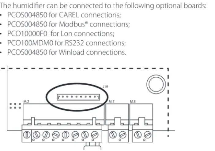
5.3 Supervisory network (J19)
The humidifi er can be connected to the following optional boards:
PCOS004850 for CAREL connections;
PCOS004850 for Modbus® connections;
PCO10000F0 for Lon connections;
PCO100MDM0 for RS232 connections;
PCOS004850 for Winload connections.
M.2 M.7
J19 M.8
Fig. 5.d (detail of the electronic board, humidifi er electrical compartment)
Important: for the tLAN and pLAN connections in residential household (IEC EN 55014-1) and residential (IEC EN 61000-6-3) environments, use shielded cable (with shield connected to GND). This warning also applies to the cables leaving the unit.
•
•
•
•
•
installer user ser vic e
6. STARTING AND USER INTERFACE
Before starting the humidifi er, check:
water connections: Fig. 2.a page 10. In the event of water leaks do not start the humidifi er before having resolved the problem;
steam distribution: Fig. 3.d page 13;
electrical connections chap. “4” page 14.
6.1 Starting
1
1 0
ON
2 if the cylinder is new, run a pre-wash cycle (the cylinder is fi lled and emptied three times, cleaning the inside walls from impurities, see par. “7.12” page 25).
6.2 Stopping
1 empty the water in the cylinder to avoid stagnation (manual drain by
“ON/OFF quick access” screen, see the following page, or par. “7.15”
page 27);
2
1
0 OFF
6.3 User interface
1 4
5 6 2
3
Fig. 6.a Key to the keypad:
button function 1 alarm list active alarms
2 PRG access the “Management menu” screen (password
= 77)
3 ESC return to “Simple” or “Main” screen 4 UP increase the set point
5 ENTER from “Main” screen: open “ON/OFF quick access”
screen
from “Simple” screen: select type of essence ENTER and PRG: move from “Simple” to “Main” screen (and vice-versa).
6 DOWN decrease the set point
The humidifi er produces steam when the temperature recorded (displayed in the centre of the screen in large characters) is less than the set point (at the top in smaller characters).
Set point: maximum temperature threshold above which the humidifi er no longer produces steam (can be changed using the UP and DOWN buttons).
To display the temperature inside the steam bath and the set point, two types of screens are available:
o o o
“Simple”: with the possibility to modify the set point and the type of essences;
“Main”: with the possibility to modify the set point, the type of essences and access the “ON/OFF quick access” and “Management menu” screens.
“Simple” screen
Fig. 6.b
Key :
symbol function
1 day and month
2 set point temperature (can be modifi ed using the UP or DOWN button)
3 temperature inside the steam bath (measured by the probe/probes)
4 hour and minutes
5 time bands set (when fl ashing indicates that a time band is in progress)
6 light on inside the steam bath Essence (e.g.
Mint)
essence enabled (delivered when the humidifi er produces steam)
“Main” screen
Fig. 6.c Key :
symbol function
1 set point temperature (can be modifi ed using the UP or DOWN button)
2 temperature inside the steam bath (measured by the probe/probes)
3 light on inside the steam bath
4 time bands set (when fl ashing indicates that a time band is in progress)
5 steam production (without “cloud” steam production in standby)
6 supply fan (fan 1) on
7 exhaust fan (fan 2) on to
8 when moving indicates the operation of the fans, when still indicates fans enabled but in standby
Essence (e.g.
Mint)
essence enabled (delivered when the humidifi er produces steam)
The following screens can be accessed from the “Main” screen:
ENTER button: “ON/OFF quick access”
PRG button: “Confi guration menu”.
•
•
installer user ser vic e
“ON/OFF quick access” screen
Fig. 6.d Used to:
enable steam production (ON) and activate the manual drain function (*);
select the type of essence (1, 2, 3);
enable the sanitisation function (ON);
switch on the light (ON).
Function buttons:
ENTER: move the cursor inside the screen;
UP or DOWN: enable/disable.
(*) Manually drain the water in the cylinder:
access the “ON/OFF quick access” screen, position the cursor on “steam”;
press the UP and DOWN buttons together for a few seconds.
The same procedure can be repeated to stop the drain cycle in progress.
Important:
the “ON/OFF quick access” screen only displays the functions enabled in confi guration phase.
with steam production disabled (OFF) the supply and exhaust fans can be enabled manually;
if the humidifi er is enabled but not producing steam, check the following possible causes:
possible cause solution
the temperature of the steam bath is higher than the set point
wait for the temperature of the bath to fall below the set point alarms are active that stop steam
production (ALARM button fl ashing).
check and resolve the error (see par. “7.13” page 26)
The humidifi er is set to “manual” deactivate the manual procedure (submenu par. “7.12”, see page 25) time bands are active (CLOCK icon
fl ashing on the display);
disable the time band (see par.
“7.5“ page 22), or modify as required.
Tab. 6.a
•
•
•
•
•
•
•
•
•
•
•
•
“Alarms” screen
Fig. 6.e Indicates an alarm is active, press to display.
“Management menu” screen
Fig. 6.f To access press:
PRG from the “Main” screen;
ENTER to move the cursor to the “0”;
UP or DOWN to enter the password “77”;
ENTER to confi rm and enter the management submenu:
User;
Essence;
Fan management;
Maintenance (info, software, hardware);
Sanitisation;
Alarm log;
Network;
GSM.
The management menu, the submenu and the screens are cyclical, and follow the same path also in the opposite direction.
•
•
•
•
1.2.
3.
4.
5.
6.
7.
8.
installer user ser vic e
6.4 Management menu
1 User Clock
Scheduler Schedule (*) Week sch. (*) T. setpoint (*) Enable descriptions (i) 2 Essences Essence 1 (*)
Essence 2 (*) Essence 3 (*) 3 Fans Supply fan (*)
Exhaust fan (*)
4 Maintenance 1 Maint info SW outputs (**) Nom. values (**) Cylinder status (**) Sys info (**) 2 Maint SW Additional features
Additional features Disable emptying Conductivity threshold Control parameters SW Input/output Backup Recovery
3 Maint HW Setup
Essences Essences Fans
Temperature probe 1 Temperature probe 2 Other options Man. procedure Manual proc.
Manual procedure 5 Sanitisation San. (*)
San. Phase 1 (*) San. Phase 2 (*) 6 Alarm log Log (**) 7 Network Supervision 8 GSM (*) SMS 1 (*)
SMS 2 (*) (**)
Tab. 6.b
(*) screens available if the functions (user, essences, fans, maintenance, sanitisation, network, GSM) have been enabled. For example: the screens in the “fans” submenu are only visible if enabled in the “Maint HW” submenu;
(**) read-only values.
Function of the keypad in the management menu
button function
alarm access the alarm screen, displaying any alarms in progress (the button fl ashes)(*)
PRG from the “Main” screen: access the management menu
ESC return to the previous screen(**)
UP e DOWN in the “management menu”: navigate the submenus, screens, parameters cyclically (also in the opposite direction)
inside a screen: modify the values of the parameters (YES/NO, ON/OFF, temperature range,…)
•
•
ENTER select a submenu, screen, parameter
save the changes to the parameters and move the cursor to the next parameter
•
•
(*) To reset an alarm in progress, press the ALARM button again.
(**)Important: before pressing the ESC button, press the ENTER button to save the last change made.
Installer’s notes
Names chosen for the essences
Essence 1: ……….
Essence 2: ……….
Essence 3: ……….
installer user ser vic e 7. MAIN CONFIGURATIONS
7.1 Language
The display terminal can be confi gured in: Italian, French, Spanish, English, German.
To change the language, from the “Main” screen press:
PRG;
ENTER;
UP or DOWN to enter the password “77”;
ENTER;
DOWN (3 times) until displaying the “Maintenance” submenu;
ENTER;
DOWN (once) until displaying the “Maint SW” submenu;
ENTER;
DOWN (5 times) until displaying “SW Input/output” screen;
ENTER (twice) to move the cursor to the parameter “language”;
UP or DOWN to change the language;
ENTER to confi rm the language selected and return to the “Main”
screen
Note: in the “SW Input/output” screen, the unit of measure can also be selected, °C-kg/h (default) or °F-lbs/hr.
7.2 Date and time
To set the date and time, access the “User” submenu and press:
ENTER to display the “clock” screen;
ENTER to move the cursor to the fi rst digit of the hour;
UP or DOWN to modify the fi rst digit of the hour;
ENTER confi rm and move the cursor to the second digit of the hour;
continue with the UP/DOWN buttons and ENTER to set the minutes, day (number), month, year, weekday (from Monday to Sunday);
7.3 Temperature probes
The humidifi er can manage up to two temperature probes:
with one probe, the value read is shown directly on the display;
with two probes, the values saved are “averaged” by the humidifi er, and the result is shown on the display (**).
The “Temperature probe” screen (“Maint HW” submenu) can be accessed to set the relevance of one probe compared the other in percentage terms (“weigh probes” parameter). In addition, for each probe the minimum and maximum of the scale and the off set can be set.
Probe settings
From the “Maint HW” submenu press:
probe 1
ENTER to confi rm
DOWN to reach the “Temperature probe 1” screen
ENTER to confi rm and move the cursor to the “type of probe”
parameter
UP or DOWN to select the type of probe (*)
•
•
•
•
probe 2
ENTER to save and move the cursor to “enable probe 2”;
UP or DOWN to enable the second probe (YES);
ENTER to move the cursor to “weigh probes” (**) (UP and DOWN to modify the weights of the 2 probes and ENTER to save and move the cursor);
ENTER to return to the start of the screen;
DOWN to access the screen “Temperature probe 1”;
ENTER to move the cursor to the min. and max. scale and off set values (UP and DOWN to modify the value and ENTER to save and move the cursor);
•
•
•
•
•
•
ESC until displaying the “Main” screen.
•
•
•
•
•
•
•
•
•
•
•
•
•
•
•
•
•
•
•
•
•
(**) to achieve a temperature value measured with two probes, the
humidifi er carries out the following calculation:
Tm= (Ts1*W1/100) + (Ts2*W2/100) Tm= temperature shown on the display Ts1 & Ts2= temperatures read by the two probes
W1 & W2= weights attributed to the two probes, percentage value (W1+W2=100)
For example, with the following values:
Ts1= 42° W1= 60%
Ts2= 44° W2= 40%
Tm= (42*60/100) + (44*40/100)= 42.8 °C
7.4 Essences
The essences are delivered into the steam bath when the humidifi er is producing steam and the temperature reaches 70% of the set point.
For example: if the set point is 50°C, the essence will be delivered when the humidifi er is producing steam and the temperature measured exceeds 35°C.
Important: make sure that the external essence pump is correctly connected.
Enabling the essences
From the “Maint HW” submenu press:
ENTER to confi rm;
DOWN to select the “Essences” screen (essences 1 and 2);
ENTER to confi rm;
UP or DOWN to enable (YES) essence 1;
ENTER to confi rm;
UP or DOWN to enable (YES) essence 2;
ENTER to confi rm;
DOWN to select the “Essences” screen (essence 3);
ENTER to confi rm;
UP or DOWN to enable (YES) output essence 3;
ENTER to confi rm;
ESC twice to return to the management menu.
Setting the essence operating times From the “Essences” submenu press:
ENTER to select the “Essence 1” screen;
ENTER to confi rm and move the cursor to the “Time ON” parameter;
UP or DOWN to modify the ON seconds for essence 1;
ENTER to confi rm and move the cursor to the “Time OFF” parameter;
UP or DOWN to modify the OFF seconds for essence 1;
ENTER to confi rm and move the cursor to the “name” parameter;
UP or DOWN to modify the name of the essence, e.g.: Menthol (*);
repeat the same procedure (ON, OFF times and essence name) for the other essences enabled;
at the end press ESC repeatedly to return to the “Main” screen.
(*) Characters and symbols available for naming the essences:
A B C D E F G H I J K L
M N O P Q R S T U V W X
Y Z 0 1 2 3 4 5 6 7 8 9
+ - * : ; , ( ) / #
Function buttons:
UP or DOWN to modify the characters;
ENTER to save and move the cursor to the next character. Up to 10 characters can be used.
•
•
•
•
•
•
•
•
•
•
•
•
•
•
•
•
•
•
•
•
•
•
•
installer user ser vic e
Up to until three essences can be set, and selected from the “ON/OFF quick access” screen or the “Simple” screen. The display will show the name or number of the chosen essence.
7.5 Time bands
These are used to switch the humidifi er on/off and change the set point at set times.
Two types of time bands are available:
1. Daily bands (“ON/OFF scheduler” parameters): set how many times to start/stop steam production over a period of 24h:
2 daily operating periods (parameters P1-1 and P1-2)
0 24h
ON
P1-1 P1-2
OFF OFF ON OFF
1 daily operating period (parameter P2)
0 P2 24h
OFF ON OFF
Humidifi er enabled all day (parameter P3)
0 24h
ON
Humidifi er disabled all day (parameter P4)
0 24h
OFF
The operating mode (P1, P2, P3, P4) can be associated with each day of the week (from Monday to Sunday).
2. “Variable set point” bands (“Temp. scheduler” parameters): four diff erent temperature set points that vary throughout the day (parameters Z1, Z2, Z3, Z4).
Z1 Z2
20°C 50°C
30°C
Z3 Z4
0 24h
The “daily” and “variable set point” time bands can be programmed to set steam production according to the requirements of the operator of the steam bath (e.g. based on closing times) and with a customised temperature trend (using the 4 set point threshold).
Note:
during the time band without operation (“OFF”), the humidifi er is NOT actually off , but rather steam production is temporarily disabled, including manually;
the “daily” time bands have priority over the “variable set point”. For example, setting P4 on Monday (steam bath closed), parameters Z1, Z2, Z3, Z4 (diff erent set point values) will be ignored, because the humidifi er is not programmed to operate on that day.
Setting the daily bands (“ON/OFF scheduler”):
From the “User” submenu press:
ENTER to confi rm;
DOWN until displaying the “Scheduler” screen;
ENTER to confi rm and move the cursor to the “ON/OFF scheduler”
parameter;
UP or DOWN to enable (YES) the daily bands;
ENTER (twice) to return to the start of the screen;
DOWN to access the “Scheduler” screen: to set the daily band start and end time (P1-1, P1-2 and P2). Use: ENTER to move the cursor and UP or DOWN to modify the value;
•
•
•
•
•
•
•
•
•
•
•
•
ENTER until move the cursor to the start of the screen;
DOWN to access the following screen, “Week sch.”: this screen can be used to assign the type of time band (P1, P2, P3, P4) to each day of the week. Use ENTER to move the cursor and UP or DOWN to modify the value;
ESC repeatedly to return to the “Main” screen.
The display shows the symbol (that fl ashes when the time bands are active).
Setting the variable set point bands (“Temp. scheduler”):
From the “User” submenu press:
ENTER to confi rm;
DOWN until accessing the “Scheduler” screen;
ENTER (twice) to confi rm and move the cursor to “Temp. scheduler”;
UP or DOWN to enable (YES) the “Temp. scheduler” parameter;
ENTER to return to the start of the screen;
DOWN until accessing the “T. setpoint” screen: this screen can be used to customise up to four set point values per day (Z1, Z2, Z3, Z4). Use ENTER to move the cursor and UP or DOWN to modify the value;
ESC repeatedly to return to the “Main” screen.
The display shows the symbol (that fl ashes when the time bands are active).
7.6 Fans
The use of the supply and exhaust fans:
guarantee air change;
perform the sanitisation cycles;
create the “mist eff ect”.
Enabling the fans
From the “Maint HW” submenu press:
DOWN until accessing the “Fans” screen ENTER to move the cursor to “supply fan”
UP or DOWN to enable (YES) the supply fan ENTER to move the cursor to exhaust fan UP or DOWN to enable (YES) the exhaust fan ESC repeatedly to return to the “Main” screen
The display shows the symbol (next to if the fans are on).
Manual fan mode
The manual management of the fans, from the “ON/OFF quick access”
screen, is only available if steam production is disabled (OFF). The manual activation of the fans during steam production is exclusively controlled from the management menu.
In this way, the fans can be started using the “ON/OFF quick access” screen (ENTER from the “Main” screen), stopping steam production (steam OFF).
When steam production is ON they will be stopped automatically.
To switch the fans on and off using the management menu (steam ON), from the “Fans” submenu press:
ENTER to confi rm and access the Supply fan and/or Exhaust fan screen (depending on the fan enabled);
ENTER to move the cursor to Mode (manual/automatic);
UP or DOWN to set “Manual”;
ENTER to move the cursor to Production (ON/OFF);
UP or DOWN to set “ON”;
ENTER to confi rm;
UP or DOWN to repeat the same operation for the other fan (if enabled);
ESC repeatedly to return to the “Main” screen
•
•
•
•
•
•
•
•
•
•
•
•
•
•
•
•
•
•
•
•
•
•
•
•
•
•
•
installer user ser vic e
The operation of the fans is bound by steam production: this is switched on and off only from the management menu (setting production “OFF”
on the fans screen).
Automatic fan mode
This varies depending on the type of fan:
supply fan: the fan stops when reaching the set point (related to steam production);
exhaust fan: the fan starts when reaching the set point, or alternatively after a set time (periodical operation, independent of steam production).
Automatic supply fan mode From the “Fans” submenu press:
ENTER to confi rm and access the “Supply fan” screen;
ENTER to move the cursor to “Mode” (manual/automatic);
UP or DOWN to set “Automatic”;
ENTER to confi rm;
ESC repeatedly to return to the “Main” screen.
The fan runs until reaching the temperature set point (related to steam production).
Automatic exhaust fan mode From the “Fans” submenu press:
ENTER to confi rm and DOWN to access the Exhaust fan screen;
ENTER to move the cursor to “Mode” (manual/automatic);
UP or DOWN to set “Automatic”;
ENTER to confi rm and move the cursor to “type”;
UP or DOWN to choose the automatic “Setpoint/Periodic”(*) mode;
ESC repeatedly to return to the “Main” screen.
(*) Setpoint: The fan starts when reaching the temperature set point and steam production stops.
Periodic: The fan starts and stops after a certain operating time (in the
“Exhaust fan” screen, set ON time and OFF time). This mode is not related to steam production or the set point.
To switch the fans on and off using the “ON/OFF quick access” screen (steam OFF), from the “Fans” submenu press:
ENTER to confi rm and access the Supply fan and/or Exhaust fan screen (depending on the fan enabled);
ENTER to move the cursor to “Mode” (manual/automatic);
UP or DOWN to set “Manual”;
ENTER to move the cursor to Production (ON/OFF);
UP or DOWN to set “OFF”;
ENTER to confi rm;
UP or DOWN to repeat the same operation for the other fan (if enabled);
ESC repeatedly to return to the “Main” screen.
7.7 Sanitisation
The sanitisation cycle is used to alternately activate the two fans:
phase T1 supply fan;
phase T2 exhaust fan.
During the operation of the fans, steam production and the sanitisation pump can be activated (to deliver the disinfecting liquid).
The activation of the sanitisation cycle can be manual (using the “ON/
OFF quick access” screen) or automatic (at the end of the last steam production time band).
Note: Automatic mode is only available when the time bands are enabled.
•
•
•
•
•
•
•
•
•
•
•
•
•
•
•
•
•
•
•
•
•
•
•
Enabling sanitisation
From the “Maintenance” submenu press:
ENTER to confi rm;
DOWN to select the “Maint HW” menu;
ENTER to confi rm;
DOWN until selecting the “Other options” screen;
ENTER to confi rm and move the cursor to “enable sanifi cat.”;
UP or DOWN to enable (YES);
ENTER to confi rm;
ESC repeatedly to return to the “Main” screen.
Manual sanitisation mode
From the “sanifi cation” submenu press:
ENTER to confi rm and open the “sanifi cation” screen;
UP or DOWN to enable manual sanitisation;
ESC repeatedly to return to the “Main” screen, or alternatively ESC twice to return to the management menu to set the sanitisation cycle times and mode.
Automatic sanitisation mode
Available only when the time bands are enabled.
Used to activate the sanitisation cycles at the “end of the day”, that is, at the end of the last steam production time band.
From the “sanifi cation” submenu press:
ENTER to confi rm and open the “sanifi cation” screen;
UP or DOWN to enable automatic sanitisation;
ESC repeatedly to return to the “Main” screen, or alternatively ESC twice to return to the management menu to set the sanitisation cycle times and mode.
Setting the sanitisation times and phases From the “sanifi cation” submenu press:
ENTER to enter the “sanifi cation” screen;
ENTER values for T1 and T2;
UP or DOWN to set the duration of the cycles in minutes;
ENTER until moving the cursor to the start of the screen;
DOWN to access the “San. phase 1” (T1) screen;
ENTER to enable the desired functions (with the UP or DOWN button) and press ENTER to move the cursor to the next parameter;
ENTER until moving the cursor to the start of the screen;
DOWN to access the “San. phase” (T2) screen, and set the second sanitisation cycle;
ESC repeatedly to return to the “Main” screen.
7.8 Advanced settings (qualifi ed personnel only)
Important: these settings should only be made by qualifi ed personnel, improper uses may cause serious damage.
Automatic water drain
Drain due to set point reduction
The humidifi er empties a small quantity of water if the requested production is decreased by more than 33%. With less water the humidifi er can reach the new steam production set point more quickly.
To disable this function, from the “Maint SW” menu press:
ENTER to access the “Additional features” screen;
ENTER to move the cursor to the “Drain by low setp” parameter;
UP or DOWN to disable (NO) or enable (YES, default) the function;
ENTER to confi rm;
ESC repeatedly to return to the “Main” screen.