We will not be held responsible for mechanical failures, system failures, device crashes or accidents caused by failure to follow instructions. Connecting these models to the MUZ-LN·VG series outdoor units enables low standby power management. These models can be connected to the MUZ-LN·VG series after they are connected to the MXZ series once and operated, for example, due to relocation.
Then the outdoor units of the MUZ-LN·VG series will not work without taking a step.
REFRIGERANT SYSTEM DIAGRAM7
For service, the following set time can be shortened by connecting the short mode point of the timer to the electronic control P.C. The time set for the ON/OFF timer can be reduced to 1 second for every minute. Once the switch is turned on, the compressor start-up time, which normally takes 3 minutes, can be reduced to 1 minute.
HOW TO SET REMOTE CONTROL EXCLUSIVELY FOR A PARTICULAR INDOOR UNIT A maximum of 4 indoor units with wireless remote controls can be used in one room.
8-2. HOW TO SET REMOTE CONTROLLER EXCLUSIVELY FOR A PARTICULAR INDOOR UNIT A maximum of 4 indoor units with wireless remote controllers can be used in a room
SERVICE FUNCTIONS8
8-3. SETTING THE INSTALLATION POSITION
When the indoor unit is controlled by the remote controller, the operation mode, set temperature and fan speed are stored by the indoor electronic controller P.C.
Operation
NOTE
WIRELESS REMOTE CONTROLLER
MICROPROCESSOR CONTROL9
INDOOR UNIT DISPLAY SECTION
8-6. CHANGING THE CORRECTION VALUE OF THE ROOM TEMPERATURE
Coil frost prevention
9-4. HEAT ( ) OPERATION
Cold air prevention control
High pressure protection
Defrosting
9-1. COOL ( ) OPERATION
- Low outside temperature operation
- Indoor fan speed control
- Vertical vane (1) Vane motor drive
- How to set the time
- To release the timer
When you try to operate 2 or more indoor units with one outdoor unit simultaneously, one for cooling and the others for heating, the operation mode of the indoor unit that operates first is selected. Other indoor units cannot operate and the operation indicator lamp flashes as shown in the figure below. The motor's direction of rotation, speed and angle are controlled by pulse signals (approx. 12 V) sent from the indoor microprocessor.
In the following cases, the horizontal vane returns to the closed position. a) When the STOP/OPERATE (OFF/ON) button is pressed (POWER OFF). Confirmation of the default position is performed in the following cases:. a) When the operation starts or ends (including timer operation). NOTE: When 2 or more indoor units are controlled with a multi outdoor unit, even if one indoor unit turns off the thermostat, this control will not work in the indoor unit.
The air conditioner automatically adjusts the fan speed and set temperature and activates the POWERFUL mode. To cancel this operation manually, select another mode or press one of the following buttons within 15 minutes after operation has started: STOP/DRIFT (OFF/ON), ECONO COOL, FAN SPEED CONTROL, CIRCULATOR or i -save button. The motor's direction of rotation, speed and angle are controlled by pulse signals (approx. 12 V) sent from the microprocessor.
At first, "0:00" flashes at the current time display of TIME MONITOR, so set the current time correctly with CLOCK button. How to set the current time (a) Press the CLOCK button. b) Press the TIME SET buttons ( and ) to set the current time. Each time FORWARD button ( ) is pressed, the set time increases by 1 minute, and each time BACK button ( ) is pressed, the set time decreases by 1 minute.
Set the time of the timer using the TIME SET buttons ( and ).* OFF timer setting. a) During operation, press the OFF TIMER button ( ). Each time the FORWARD button ( ) is pressed, the set time increases by 10 minutes: each time the BACKWARD button ( ) is pressed, the set time decreases by 10 minutes.
PROGRAM TIMER
How to set the weekly timer
When the weekly timer is ON, the day of the week will be lit, the timer setting is complete.
Checking weekly timer setting
Even if the unit is turned off due to No Occupancy Auto-OFF mode, the remote control display will continue to indicate that the unit is operating. Press the STOP/OPERATE(OFF/ON) button and then press the STOP/OPERATE(OFF/ON) button again to restart operation. No Occupancy Power Saving Mode or No Occupancy Auto-OFF Mode are not available during POWERFUL operation.
The unit will not turn off if no one is detected during normal operation, even if the unoccupied auto-off mode is activated. This function automatically changes the operation to energy-saving mode without presence or auto-off mode without presence when there is no one in the room.
9-10. AIRFLOW CONTROL MODE
The unit will not turn off if no one is detected during normal operating mode, even though the No Occupancy Auto-OFF mode is enabled. press the SENSOR button until the remote control. In the AIR PURIFYING function, the indoor unit's built-in device reduces fungi, viruses, mold and allergens in the air. Although the air cleaning device is a safety conscious design, touching this device may cause trouble as this device discharges high voltage electricity.
The AIR PURIFYING lamp does not light up if the front panel is not completely closed.
9-11. NIGHT MODE ( ) OPERATION
Emergency operation is available when the remote control is missing or defective, or when the batteries in the remote control are running low. The indoor fan is running at high speed and the temperature control is not working. In the test run or emergency operation, the horizontal vane operates in VANE AUTO ( ) mode.
Emergency operation continues until the EMERGENCY OPERATION switch is pressed once or twice or the device receives a signal from the remote control. When the system is shut down, the compressor will not restart for 3 minutes as the 3 minute delay function kicks in to protect the compressor from overload.
9-15. CIRCULATOR OPERATION
Before troubleshooting, check the following 1) Check the power supply voltage
Take care of the following during servicing
Troubleshooting procedure
How to replace batteries
TROUBLESHOOTING10
- Flow chart of failure mode recall function for the indoor/outdoor unit
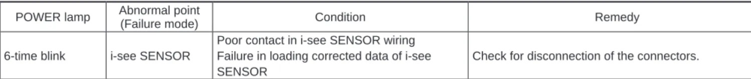
- Flow chart of AIR PURIFYING power failure mode and i-see SENSOR failure mode recall function
- AIR PURIFYING power operation check
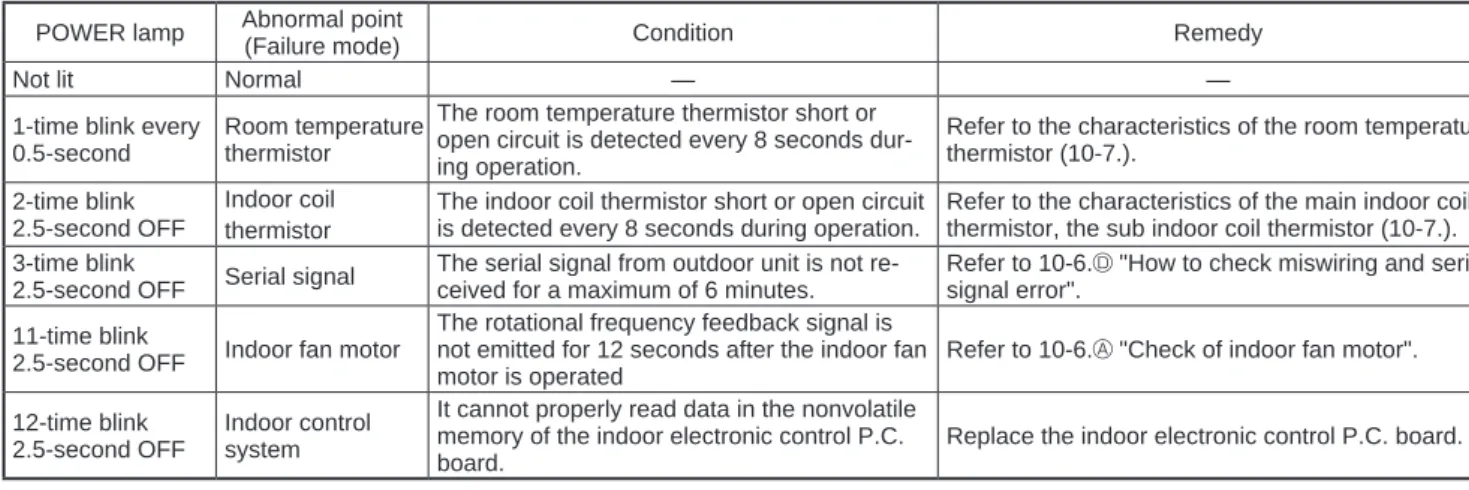
- Table of indoor unit failure mode recall function (When recalled at a set temperature of 24°C) POWER lamp Abnormal point
- Table of indoor unit failure mode recall function (When recalled at a set temperature of 23°C) Table of AIR PURIFYING power failure mode recall function
- Operation check on i-see SENSOR
- Check of the unit
Check whether the outdoor unit is abnormal according to the detailed recall function of the outdoor unit error condition. Check the flashing pattern and identify the abnormal point by referring to the indoor unit fault condition recall function table. Be sure to check at least 2 consecutive flashing cycles.*2 Releasing the error condition recall function.
Check the flashing pattern and identify the abnormal point by referring to the indoor unit fault condition recall function table. After repairing the device, recall the failure mode according to "Setting the failure mode recall function" mentioned above. Press the STOP/OPERATION (OFF/ON) button on the remote controller (the set temperature is displayed) with the remote controller pointed at the indoor unit.
4 Release the fail-mode recall function according to "Releasing the fail-mode recall function" men-. Be sure to release the fail-mode pullback function after it is configured, otherwise the unit may not function properly. Press the STOP/OPERATE (OFF/ON) button of the remote control (set temperature is displayed) with the remote control pointed at the indoor unit.
Flowchart of AIR PURIFYING power failure mode and i-see SENSOR failure mode calling function. Check the flashing pattern and identify the anomalous point using the AIR PURIFYING power supply table or i-see SENSOR failure mode recall function (10-2.5.). AIR PURIFYING power turns ON when the PURIFIER button on the remote controller is pressed while each set temperature is displayed during the failure mode recall function.
If the flashing of the OPERATION INDICATOR cannot be verified, it can be verified using the fault mode recall function. NOTE: The indoor unit may be connected to an outdoor unit that is not in low power standby mode.
10-5. TROUBLE CRITERION OF MAIN PARTS
The operation mode of each indoor unit is set differently to COOL (include DRY, WANDER) and HEAT at the same time, the operation mode of the indoor unit which was in operation first has the priority.
10-6. TROUBLESHOOTING FLOW
No No Has the indoor unit ever been connected to the Multi (MXZ) series and operated (on). Is there faulty wiring, poor contact or disconnection of the internal/external connecting wire. Excessive dirt on the air cleaner may cause abnormal discharge, clean it.
Be sure to attach the air purifier after cleaning as it is completely dry. If the AIR PURIFYING operation check is performed while the air purifier is wet, the protection is activated and the AIR PURIFYING lamp also flashes continuously. Pay close attention and never touch the air purifier and the high voltage cord.
Operate and idle the ignition switch (air cleaner) using something like a screwdriver and measure the resistance between CN1R1 and the internal electronic control P.C. Does the ignition switch (air cleaner) work? Air cleaner) Does not work (close) using something like a screwdriver.
E Check of AIR PURIFYING power
Make sure that the indicators on the LCD screen shown in the right figure are all displayed. The operation of the lock switch (air cleaning device) due to incomplete closing of the front panel may cause flashing 2 times. If it runs normally without turning off and on, the AIR PURIFYING lamp does not turn off.).
Is the voltage between CN1T1 (+) and (GND) on the electronic control P.C. board) 0V with the unit stopped. Yes Is the distance between the antennas and the indoor unit within 3 m, or is the distance between the antennas and the outdoor unit within 3 m. Extend the distance between the antennas and the indoor unit, and/or the antennas and the outdoor unit.
Is the distance between TVs or radios and the indoor unit within 1m, or is the distance between TVs or radios and the outdoor unit within 3m. Extend the distance between the indoor/outdoor connecting wire of the air conditioner and the antenna connection. Even if all the above conditions are met, electromagnetic noise may enter, depending on the strength of the electric field or the condition of the installation (combination of specific conditions such as antennas or wiring).
Indoor power P.C. board
Switch buzzer P.C. board
10-7. TEST POINT DIAGRAM AND VOLTAGE
Display and receiver P.C. board
OPERATING PROCEDURE PHOTOS/FIGURES
Removing the front panel and the panels (U/R/L/F) Removing the front panel (Photos 1, 2)
DISASSEMBLY INSTRUCTIONS11 DISASSEMBLY INSTRUCTIONS
- Removing the Wi-Fi interface (Photos 4, 8) (1) Remove the front panel and the panels (U) (R) (L)
- Removing the indoor electrical box (Photos 4, 5, 6, 7, 8)
- Removing the indoor electronic control P.C
- Removing the outer vane motors (horizontal) (Photos 8, 10, 11, 12, 13)
- Removing the vane motor units (L) (R) (vertical) and the vane motors (horizontal)
- Removing the air purifying device (Photo 8, 18) (1) Remove the front panel, the outer vanes (R) (L)(hori-
- Removing the line flow fan, the indoor fan motor assembly, the indoor coil thermistor, and the
CN151 (Blade motors) CN112 (Inner coil thermistor) CN1T1 (Air cleaner) (14) Remove the electrical box. Electrical Box Screw Remove SCREEN AND. i-see sensor assembly in the direction of. Then move them in the direction of , and remove the leaf motor unit connection (L) (vertical).
Fixing the indoor coil thermistor
Holder shapeClip shape
Position and procedure for mounting the clip-shape part