For repairs to the cooling systems, (1-3) through (1-7) must be completed before work is performed on the systems. Where electrical components are changed, they must be fit for purpose and to the correct specification. This will be reported to the owner of the equipment so that all parties are notified.
When accessing the refrigerant circuit to make repairs - or for any other purpose - conventional procedures should be used. Before refilling the system, it should be pressure tested with the appropriate purge gas. The appliance must be labeled stating that it has been deactivated and emptied of refrigerant.
In addition, a set of calibrated scales should be available and in good working order. The recycled refrigerant must be returned to the refrigerant supplier in the correct recycling cylinder, and the relevant waste transfer note arranged. The evacuation process will be carried out before the compressor is returned to the suppliers.
Only electrical heating of the compressor body should be used to speed up this process.
OUTLINES AND DIMENSIONS6
Unit: mm
OBH843C
7 WIRING DIAGRAM
REFRIGERANT SYSTEM DIAGRAM8
SERVICE FUNCTIONS9
9-1. TIMER SHORT MODE
How to modify the electronic control P.C. board
9-2. HOW TO SET REMOTE CONTROLLER EXCLUSIVELY FOR A PARTICULAR INDOOR UNIT A maximum of 4 indoor units with wireless remote controllers can be used in a room
How to set the remote controller
NOTE
9-3. AUTO RESTART FUNCTION
Operation
WIRELESS REMOTE CONTROLLER
MICROPROCESSOR CONTROL10
INDOOR UNIT DISPLAY SECTION
10-1. COOL ( ) OPERATION
Coil frost prevention
Low outside temperature operation
10-3. FAN ( ) OPERATION
10-4. HEAT ( ) OPERATION
Cold air prevention control
High pressure protection
Defrosting
Mode selection (1) Initial mode
Mode selection is performed when multi standby (refer to NOTE 2) is released and the unit starts operation with ON-timer
If 2 or more indoor units are operating in multi system, there might be a case that the indoor unit, which is operating in AUTO ( ), cannot change over the other operating mode (COOL ↔ HEAT) and becomes a state
At the beginning of AUTO mode, the airflow direction and the fan speed are set to AUTO and the air outlet selection is set to 2 FLOW
10-6. AUTO VANE OPERATION
Horizontal vane (Horizontal vane/Multi-flow vane) (1) Vane motor drive
In the following cases, the horizontal vane returns to the closed position. a) When the STOP/OPERATE (OFF/ON) button is pressed (POWER OFF). During COOL or DRY operation with the angle at angle 3 or 4, when the cumulative operating time of the compressor exceeds 1 hour, the angle will automatically change to angle 1 to prevent fogging. When the ECONO COOL button is pressed in COOL mode, the set temperature is automatically set 2°C higher by the microprocessor.
To cancel this operation, select another mode or press one of the following buttons in ECONO COOL mode:. In VANE AUTO mode, the microprocessor automatically determines the vane angle for optimal room temperature distribution. The current time display on the TIME MONITOR will initially flash “0:00”, so set the current time correctly with the CLOCK button.
How to set the current time (a) Press the CLOCK button. b) Press the TIME SET ( and ) buttons to set the current time. Each time the FORWARD ( ) button is pressed, the set time increases by 1 minute, and each time the BACKWARD ( ) button is pressed, the set time decreases by 1 minute. Set the timer time using the TIME SET ( and ) buttons. a) Press the OFF TIMER button ( ) during operation.
Each time the FORWARD ( ) button is pressed, the set time increases by 10 minutes: each time the BACKWARD ( ) button is pressed, the set time decreases by 10 minutes.
To release the timer
PROGRAM TIMER
How to set the weekly timer
Press the and buttons to continue setting the timer for other days and/or numbers. 5) Press the button to turn on the weekly timer. When the weekly timer is ON, the day of the week whose timer setting is complete is lit.
Checking weekly timer setting
How to cancel operation
Emergency operation is available when the remote control is missing or has failed, or when the batteries in the remote control are running low. The indoor fan runs at high speed and the temperature control does not work. In COOL MODE, air outlet selection is set to 2 FLOW during test run.
In the test run or emergency operation, the horizontal vane operates in VANE AUTO ( ) mode. Emergency operation continues until EMERGENCY OPERATION switch is pressed once or twice or the unit receives any signal from the remote control. When the system turns OFF, compressor will not restart for 3 minutes as the 3-minute time delay function works to protect compressor from overload.
TROUBLESHOOTING11
Take care of the following during servicing
Troubleshooting procedure
How to replace batteries
Description of multi system air conditioner
11-2. FAILURE MODE RECALL FUNCTION
Flow chart of failure mode recall function for the indoor/outdoor unit
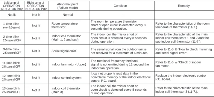
Table of indoor unit failure mode recall function
Check the room temperature thermistor and the internal coil thermistor. board or an external electronic controller P.C. Left light flashes 14 times or more Cause:. 34;How to check the miswiring and serial signal error (when the outdoor unit does not work)". If the flashing of the OPERATION INDICATOR lamp cannot be checked, you can check it with the fault mode recall function.
11-3. INSTRUCTION OF TROUBLESHOOTING
11-4. TROUBLESHOOTING CHECK TABLE
When the operation mode of each indoor unit is differently set to COOL (including DRY) and HEAT at the same time, the operation mode of the indoor unit that has been operating first has priority.
11-6. TROUBLESHOOTING FLOW A Check of indoor fan motor
Turn on an AM radio and press the STOP/OPERATE (OFF/ON) button on the remote control. 1 View the image of the remote control signal transmission section through the monitor of a digital camera or a camera phone. It is normal if the signal transmission section LED lights up when STOP/.
However, it can be difficult to see the illuminated LED of the signal transmission part with a smartphone camera. 2 If the inverter fluorescent light is turned on when the room is cool, the unit may have difficulty receiving the signal from the remote control or may not work with it; if the inverter fluorescent light is turned on when the room is warm, the unit may work with the remote control.
Check of indoor electronic control P.C. board and indoor fan motor C
Is there any misconnection, poor contact or wire disconnection of the indoor/outdoor connecting wire.
Electromagnetic noise enters into TV sets or radios E
Indoor electronic control P.C. board
11-7. TEST POINT DIAGRAM AND VOLTAGE
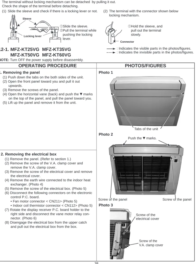
Removing the panel
Photo 5) (6) Disconnect the following connectors on the electronics. right side and disconnect the blade motor relay connector.
DISASSEMBLY INSTRUCTIONS12
OPERATING PROCEDURE PHOTOS/FIGURES
How to remove the multi-flow
Removing the horizontal vane motor (1) Remove the panel. (Refer to section 1.)
Connect the connectors to the horizontal vane motors by referring to the colors, red and white, noted on the vane motor support.
Removing the line flow fan and the indoor fan motor
Removing the R32 sensor