Do not power or operate the device if it is flooded or submerged. Can cause damage to buildings and equipment. During installation, keep the unit upright to prevent damage to the compressor, piping and components.
Model Number and Nomenclature
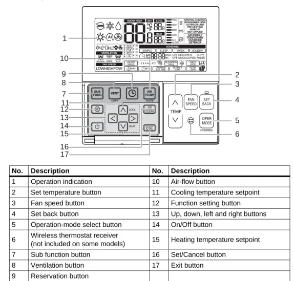
Product Introduction
4 Reset button 13 Up, down, left and right buttons 5 Operating mode selection button 14 On/off button. not included on some models) 15 Heat temperature set point. Some settings and functions may not appear or the menu name may be different depending on your system and model.
Electrical Data
R410A Refrigerant
Installation
Selecting the Location for the Outdoor Unit
Ambient air conditions
Avoid exposing the unit to exhaust from boiler stacks, chimneys, steam relief ports, other air conditioning units, kitchen vents, plumbing ducts, or substances that may degrade performance or cause damage to the unit. When installing multiple outdoor units, avoid placing units where the exhaust of one outdoor unit will blow into the inlet side of an adjacent unit.
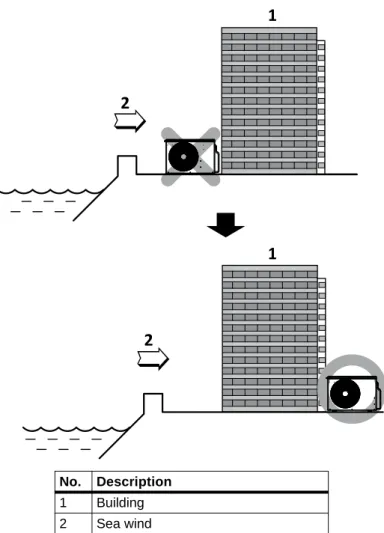
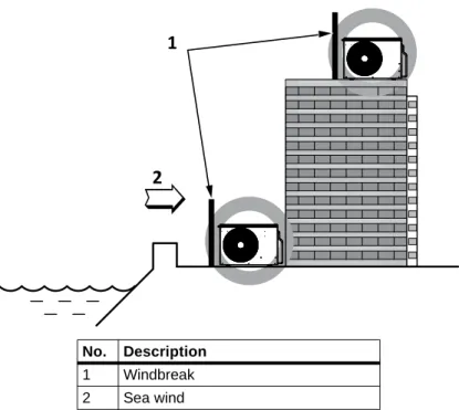
Oceanside Applications
If venting is not possible, a larger building or structure should be used to protect the outdoor unit from direct exposure to the sea breeze. The unit should be placed on the side of the building directly opposite the wind direction as shown in Figure 3-2.
Mounting the Outdoor Unit
Mounting Platform
Tie-downs and Wind Restraints
Snow and Ice Conditions
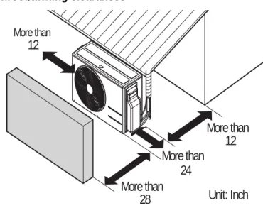
Clearance requirements
Outdoor Unit Clearance
In Figures 3-6 and 3-7, the obstacle on the output side is lower than the outdoor unit.
Indoor Unit Clearance
Installing the Indoor Unit
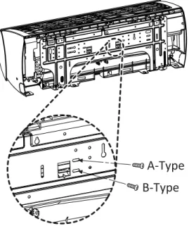
- Mounting the Installation Plate to the Wall (SRC18)
- Mounting the Installation Plate to the Wall (SRC24, SRC36)
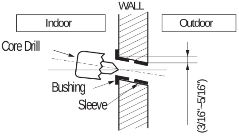
- Drilling a Piping Hole in the Wall
- Mounting the Indoor Unit to the Plate
- Prepare for Piping/Electrical Connection
Connect the hooks on the top of the indoor unit to the top edge of the installation plates. Move the bottom of the unit to the installation plate to anchor it to the wall, Figure 3-15.
Pump Down Procedure
Refer to 6.0 - Electrical Connections, to continue with the electrical conduit/wires in the indoor unit. Turn on the power switch of the cooling unit and start cooling mode operation, 8.3 - Activation of cooling only mode.
Installation Checklist
Piping
All communication cables were a minimum of 18-AWG, 4-conductor, shielded and stranded, with insulating material per local code. Appropriate crimp tooling was used to secure ring or spade terminals to all electrical wiring and control cable terminations. All power and control wires have been properly separated using the recommended distance specified in the installation manual.
Piping Preparation
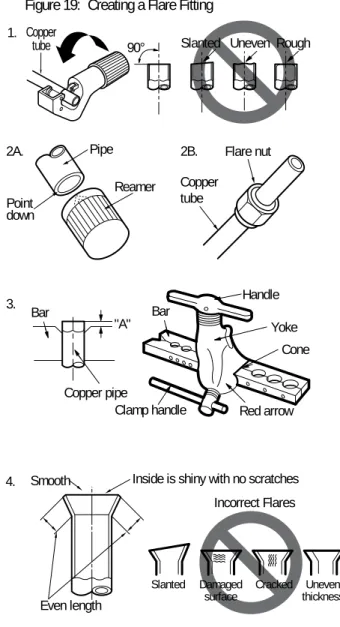
- Creating a Flare Fitting
- Tightening Flare Nuts
- Loosening Flare Nuts
- Brazing Practices
- Refrigerant-piping System Insulation
- Selecting Field-supplied Copper Tubing
- No Pipe Size Substitutions
- Obstacles
- Copper Expansion and Contraction
- Pipe Bends
- In-line Refrigeration Components
- Field-provided Isolation Ball Valves
- Using Elbows
- Pipe Supports
- Pipe Sleeves at Penetrations
- Underground Refrigerant Piping
When burrs are removed, the end of the copper pipe points down to prevent foreign material from being introduced into the pipe. When an obstruction, such as an I-beam or concrete T, is in the way of the planned refrigerant piping run, it is best practice to route the piping over the obstruction. The natural fixed end of the pipe segment is typically where the expansion loop or U-bend should be.
In Table 5-7, find the line that corresponds to the actual length of the straight pipe segment. Place a second layer of pipe insulation jacket insulation to prevent rubbing and compression of the primary insulation within the confines of the carrier pipe clamp. The diameter of the holes must be determined by the diameter of the pipe and the thickness of the insulation.
Refrigerant piping that is installed underground must be routed within a vapor-tight protective sleeve to prevent insulation deterioration and water ingress.
Piping Connections
- Connection Limitations
- Piping Connections Layout
- Pipe bundling
- Bundling and Trap when Indoor Unit is above Outdoor Unit
- Bundling and Trap when Indoor Unit is below Outdoor Unit
- Routing the Drain Hose for Indoor Unit
- Installing a Drain Hose on the Outdoor Unit
- Connecting Piping on the SCR18 Outdoor Unit
- Connecting Piping on the SCR24 and SCR36 Outdoor Unit
- Connecting Piping on the Indoor Unit
However, if you install the outdoor unit in a higher position than the indoor units, the basic pipe connections still apply. The tubing should slope at an angle where it is higher at the indoor unit and lower at the outdoor area, allowing gravity to push condensation down and out. Do not use a drain hose with the outdoor unit in cold climates, as the drain water may freeze and reduce heating performance.
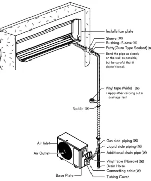
While following this procedure, refer to 5.3.2.1 - Piping Bundling for specific bundling instructions, and to 5.3.3 - Indoor Unit Drain Hose Routing for proper drain slope during piping. As shown in Figure 5-31, completely wrap the connecting pipe and the indoor unit pipe in insulating material by tying them together with vinyl tape. Continue to twist the indoor unit pipe connection to the outdoor unit as shown in Figure 5-33.
The tape should overlap the pipe and fit into the rear pipe housing on the rear of the indoor unit as shown in Figure 5-35.
Piping Insulation
Minimum Requirements for Wall Thickness
Typical location (with air conditioning): Where the pipe passes and the indoor area where the indoor unit operates. When the location is air-conditioned but has large temperature/humidity differences due to high ceilings. Typical (non-air conditioned) location: When piping runs through an indoor area where the indoor unit is not operating.
When the piping passes through an indoor space where the indoor unit does not operate. When the humidity is high and there is no air flow in the place where the pipes are installed.
Air Purging
Piping Leak Test
- Connecting the pressure gauge
- Soap-and-Water Leak Testing
- Ambient Temperature for Leak Test
Evacuation
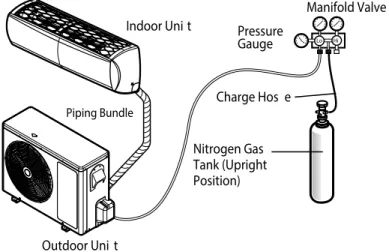
Connect the manifold valve (which includes the pressure gauges) and the dry nitrogen gas cylinder to the service valves using the fill tube, Figure 5-41. Pressurize the system to a maximum of 550 psig with dry nitrogen and close the cylinder valve when the gauge reaches 550 psig. To prevent liquid nitrogen from entering the refrigerant system, the top of the cylinder must be higher than the bottom when pressurizing the system.
If the ambient temperature has changed between the time the pressure was applied and the time the pressure drop was checked, adjust the results by factoring in approximately 1.45 psi for each 2°F temperature difference. Correction formula = (ambient temperature when pressure was applied - ambient temperature when pressure drop was checked) x 0.01. Run the vacuum pump until the system is evacuated to 300 microns and continue to run the pump for an additional 15 minutes.
When the proper vacuum is reached, close the manifold valve "Lo" button and stop the vacuum pump.
Removing Purge and Test Equipment
Electrical Connections
In both cases, it is essential that the length of the horizontal part of the pipe above or below the obstacle is at least 3 times the longest vertical rise (or fall) at both ends of the segment, Figure 5-6. This fixed point is located at the midpoint of the segment, assuming that the entire pipe is insulated in a similar manner. Place the valves with a minimum clearance of 3 to 6 inches of pipe on either side of the valve and place them between 6 and 12 inches from the outlet pipe to the main pipe up.
A properly installed piping system has adequate supports to prevent pipes from sagging during the life of the system. Emerson requires that all pipe penetrations through walls, floors and pipes buried underground be properly insulated and routed through an appropriate wall sleeve of sufficient size to prevent compression of refrigerant pipe insulation and free movement of the pipe within the sleeve, Figure 5- 10. Place a few drops of coolant oil on the opening edge of the flare before mounting, making sure not to introduce any contamination, and tighten the flare nut by hand.
Unscrew the 3 screws on the bottom of the chassis cover, Figure 5-29, and remove the chassis cover, taking care not to scratch the main horizontal fan. From the rear of the indoor unit, pull the tube holder away from the unit as shown in Figure 5-30. The thickness of the above insulation material is based on thermal conductivity of 0.61 Btu/in/h/ft2/°F.
Power-supply/Power-wiring Specifications
If there is a possibility of reversed phase, phase loss, momentary blackout, or power cycling on and off while the system is running, install a field supplied phase loss protection circuit. Best practice is to use ring or spade terminals to terminate the power supply wiring at the power terminal block, Figure 6-2. Can cause damage to buildings and equipment, excessive heat at the ends, smoke, fire, electric shock, serious injury and death.
Loose wiring can cause heat and fire. Do not ground the shield of the communication cable to the frame of the indoor unit or other grounded elements of the building.
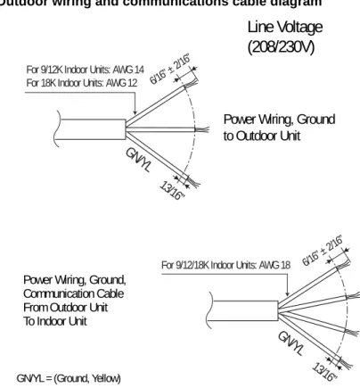
Communication-cable Specifications
Communication Cables between the Unit and Controller
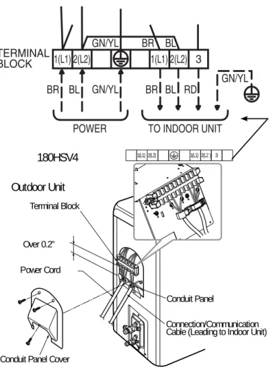
Terminal-block Connection for SRC18
The terminal block is located behind the discharge hose and bundled pipes on these units.
Terminal-block Connection for SRC24, SRC36
Connecting Outdoor Unit Electrical Wiring
On some models, the connection is located on the side of the terminal block itself.
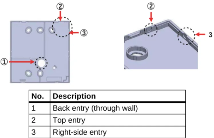
Thermostat Installation and Wiring
If using the top or right entry, remove the cable routing groove from the backplate with long pliers, Figure 6-15. If there is an electrical box, the back plate is mounted on the box during installation. Do not leave a gap between the wall and the back plate, as the thermostat may move or vibrate.
Make sure the cable does not interfere, place the upper part of the thermostat on the back plate as shown in Figure 6-17 and press the lower part on the back plate to connect it. To remove the thermostat from the backplate, insert a screwdriver into one of the separating holes on the bottom of the thermostat and turn. See Figure 6-18 to connect the indoor unit to the thermostat using the extension cord.
Connect the wires to the thermostat terminal block and the indoor unit terminal block as shown in Figure 6-20.
Installation Set-up and System Start-up
Accessing Installer Set-up Mode
Running Test Mode
During the test operation, press any of the following buttons to exit the test: operation mode, temperature up/down, fan speed, wind direction or start/stop.
Setting the Address of Central Control
Setting E.S.P
Setting the Thermistor
Setting the Ceiling Height
Setting Fahrenheit/Celsius
Setting Optional Functions
Setting Temperature Range
Operation
Operating the Unit
Automatic Unit Restart
Enabling Cooling-only Mode
Disabling Cooling-only Mode
Standard Operation
- Selecting Cooling Mode
- Selecting Power Cooling
- Selecting Heating Mode
- Selecting Dehumidification Mode
- Selecting Fan Mode
- Selecting Auto Mode
- Selecting Timed Override
- Selecting Set Back
- Setting the Temperature
- Adjusting Air Flow
- Selecting Energy-saving Cooling
- Selecting Automatic Drying
- Selecting Fan Auto
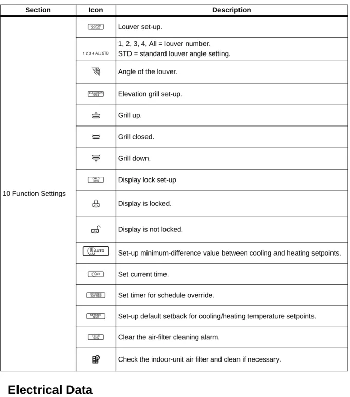
- Setting Louver Angle Control
- Locking the Display
- Setting the Minimum Difference between the Cooling and Heating Setpoints
- Setting Current Time
- Setting Override Time
- Setting Set-back Temperature
- Clearing the “Clean Filter” Alarm
Automatic drying dries the interior of the indoor unit when it is turned off by using the fan to remove moisture and prevent mold. In Auto mode, both setpoints adjust automatically when you set the temperature this way. To adjust the cooling or heating set point individually, press the appropriate button before adjusting the temperature.
Energy saving mode can only be configured in cooling mode and does not work with automatic mode. Press to select the vane number, or All to set all vanes at once (STD sets all slats to factory default). Press repeatedly until the Function Settings section of the display flashes and the Cool setpoint temperature flashes in the Temperature section.
Press to select the cooling set point, then press to go to the heating set point temperature.
Schedule Set-up
- Simple Schedule
- Sleep Schedule
- Weekly Schedule
- Copy/Paste a Schedule
- Schedule a Holiday
- Delete all Schedules
Press to select "Occupied" or "Occupied", then press to move to the "Operating Mode" section. Set the heating setpoint for the schedule, then press to move to the Fan Speed section. Press to select the day you want to paste the schedule, then press for 3 seconds.
Maintenance
Cleaning the Air Filter
Cleaning the Air Filter on Type 1 Units
Cleaning the Air Filter on Type 2 Units
Cleaning the Optional 3M or Triple Filter
Troubleshooting
Self-diagnosis at the Indoor Unit
Before Calling for Service
Self-diagnosis at the Thermostat
Troubleshooting Error Codes at the Indoor and Outdoor Units
Troubleshooting Table
Refrigerant Leaks
If the calculation indicates that the potential refrigerant concentration level is higher than the allowable RCL, increase the cubic volume of the smallest occupied space or change the design of the piping system. The allowable RCL limit for most applications should be equal to or less than 0.026 lbs/ft3. However, in special occupied spaces, such as hospitals and nursing homes, where the residents may have limited mobility, the permitted RCL limit is halved.