The product must be installed with the earth connection, using the special yellow-green connector on the terminal block. The installation, operation and maintenance must be carried out in accordance with the instructions provided in this manual. All other uses and modifications made to the device not authorized by CAREL S.p.A.
Responsibility for injuries or damage caused by improper use of the device is the sole responsibility of the user. All service and/or maintenance work must be performed by professional and qualified personnel who are familiar with the necessary precautions. The symbol (crossed out wheelie bin) shown on the product or on the packaging and instruction sheet indicates that the equipment was placed on the market after 13 August 2005 and must be disposed of separately;
To prevent stagnant water settling in the device and consequently the spread of bacteria dangerous to health, automatic supply tank emptying cycles are activated. The operation of the humiDisk65 is controlled by an electronic board which, in addition to managing the normal operation of the device, also ensures regular automatic washing cycles of the supply tank, to prevent stagnant water settling inside the device and consequently the spread of bacteria which is dangerous to health.
General safety instructions
The antifreeze device (code UCKH70W000), an accessory available on request with the UC0650D000, allows humiDisk65 to operate at temperatures down to -2°C.
Applications
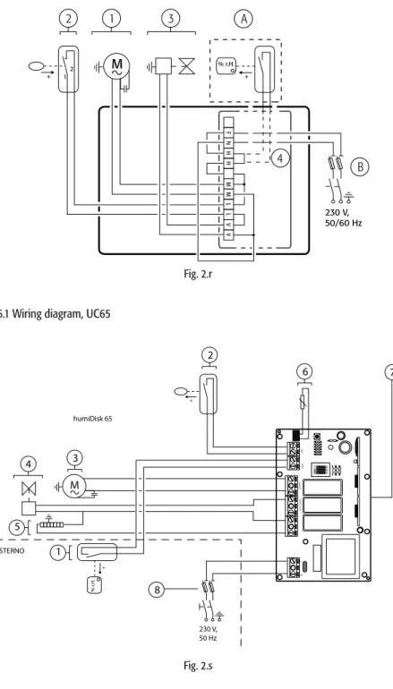
Electrical panels for humiDisk 65
Humidistat and humidity probes
Accessores for humiDisk 65
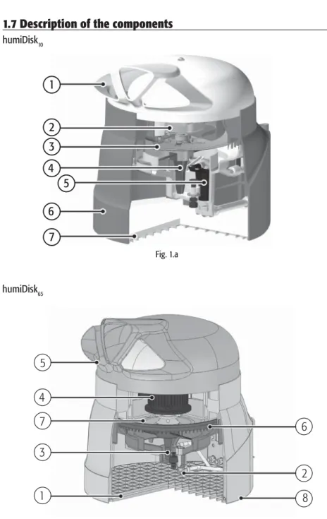
Description of the components
Before starting work, check that all the material listed below is included in the packaging. Then make sure that all the necessary connections for the correct operation of the device are properly prepared. For the humiDisk10, all connections, electrical and water, are located at the back, as shown in Figure 2.a.
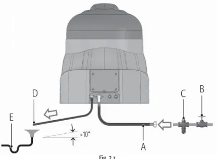
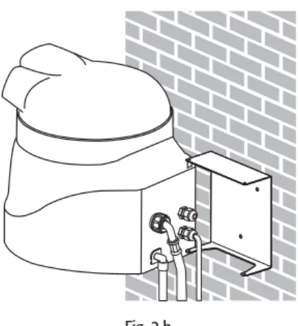
In any case, the above operations can also be performed with the device installed. For the humiDisk65, all connections, both electrical and water, are also located at the back, as shown in Fig. 2.b. In any case, the above operations can also be performed with the device installed.
INSTALLATION 9
- Preliminary operations
- Positioning
- Wall mounting
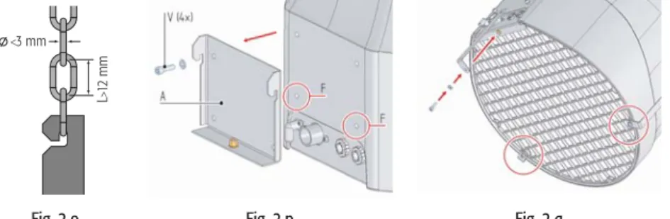
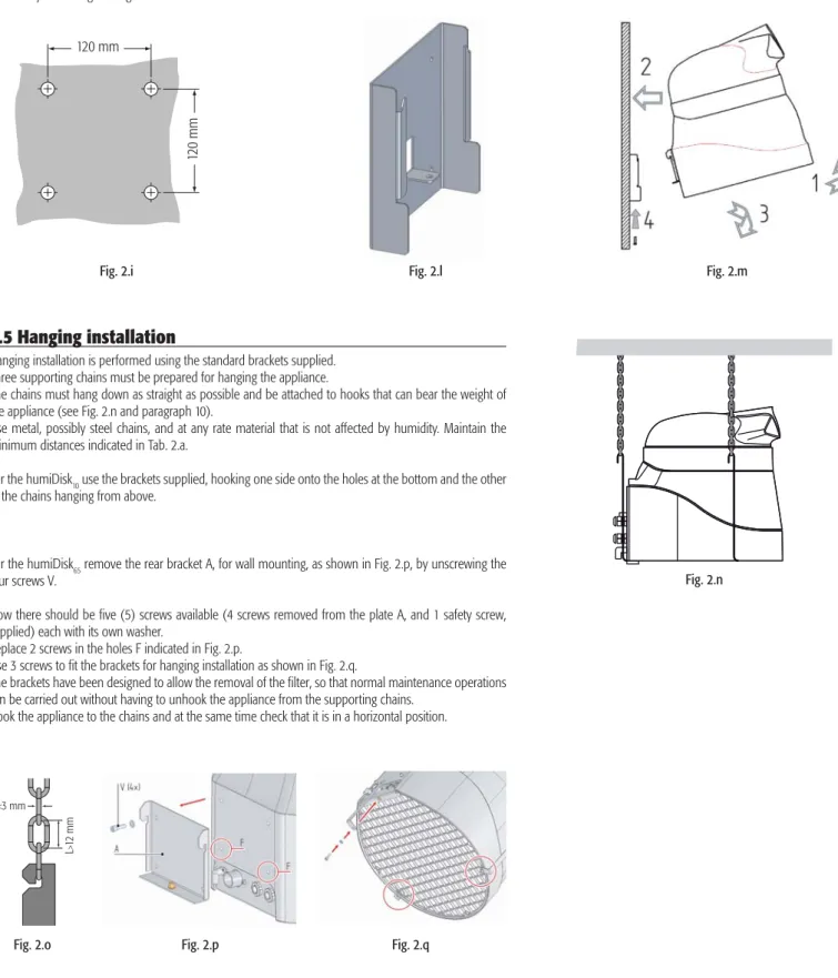
- Hanging installation
- Electrical connections
- Water connections
- Final operations
To carry out maintenance where necessary and for the correct operation of the device, the minimum suggested distances must be maintained when placing the humidifier. Tighten two of the screws securing the humiDisk10 to the bracket (not completely), as shown in Fig. The chains must hang down as straight as possible and be attached to hooks that can support the weight of the device (see Fig. 2.n) and paragraph 10).
The brackets are designed to allow the filter to be removed so that normal maintenance work can be carried out without having to detach the appliance from the support chains. Installation requires the use of an ON/OFF humidifier that controls the operation of the humidifier: a simple ON/OFF contact can be used instead, with the only difference being that the device must be started and stopped manually. Important: a device must be installed to isolate the device from the power supply, as shown in fig.
When choosing the switch or humidistat to be connected to the "HH" terminals, check the compatibility of the humidifier power and current input values shown in Tab. At the end of the installation, the inside of the device should appear as shown in Fig. Installing the humidifier also requires connecting the water supply and drain hoses.
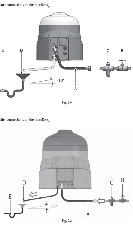
The supplied hoses should be connected to the device as shown in Figure 2.v for the humiDisk10 and Figure 2.z for the humiDisk65. A mechanical filter C must be placed behind the tap B, as shown in Fig. Important: To ensure proper drainage of the water, make sure that the drain hose is slanted and straight, with no bends or kinks.
The box must have the surface of the cover resting on the two surface locations, as shown in fig. To do this, loosen the screws that hold the diffuser on top of the appliance; see position 1 in fig. At the end of the cycle, if the hygrostat switch is closed, the humidifier starts the motor and begins to atomize the water.
STARTING, CONTROL AND STOPPING 15
Starting
The appliance will perform a washing cycle lasting approximately one minute, as described in detail in par. Important: if the ON/OFF contact is used instead of the humidistat, it must be manually closed to turn on the device, otherwise it will not start at the end of the wash/reset cycle.
Stopping
In the table (fig. 4.a), capacity regulation is carried out by combining the position of the dip switches according to the table to the side. The capacity can be adjusted during the installation phase, or later, for example to adapt the device's operation to variations in the conditions of the environment where it has been installed. The purpose of this cycle is to prevent water from accumulating in the appliance when it is not in use, thus preventing the spread of bacteria.
Stop the motor, with a waiting period of 40 seconds: this waiting period gives the motor (and therefore the fan/disc unit) time to stop completely, and allows the water in the device to collect in the bottom of the tank. Activation of the water filling solenoid valve: the water enters the tank until the level sensor switches off. Maintaining the water filling solenoid valve activated for 10 seconds after the level sensor has activated: in this way the water level in the tank exceeds the normal operating level and the drain siphon is filled and thus drains the water in the tank.
Waiting for a certain time of 10 seconds: this time period is needed to make sure that all the water in the tank has been drained. End of wash/empty cycle: at the end of the wash/empty cycle, the device waits for the humidistat contact to close or, if already closed, starts the motor and starts humidifying again. Note: when using CAREL electric panels, the washing cycle can be extended when the humidifier, in the on status, is activated by the humidity probe for a new production cycle (see chapter 9 in the manual).
ELECTRONIC CONTROLLER FOR HUMIDISK 65 16
Dip-switch
Adjusting the humidifi cation capacity
Washing/emptying cycle
Washing/emptying cycle using CAREL electrical panels
ANTIFREEZE DEVICE FOR HUMIDISK 65 17
However, a series of simple maintenance operations must be performed, with a frequency that depends on the environmental conditions in which the humiDisk operates and on the quality of the water supply. IMPORTANT: Before performing any maintenance, open (turn off) the main switch and wait for the device to come to a complete stop. Before turning on the device again, properly perform all checks, as described in this manual.
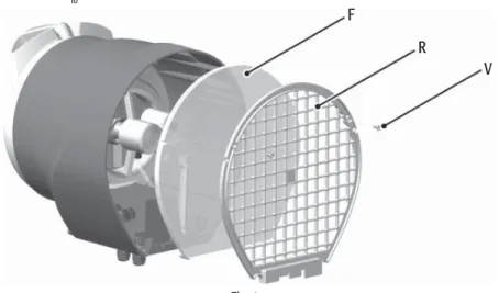
The filter must be cleaned periodically, as the build-up of dirt and dust reduces the airflow and thus the efficiency of the device.
MAINTENANCE 18
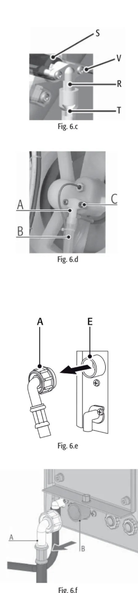
Inspecting and cleaning the drain siphon
The drain siphon may need to be cleaned periodically: accumulation of dirt inside the siphon can compromise operation.
Inspecting and cleaning the fi ll solenoid valve
Checking the washing/emptying cycle for humiDisk 65
Check that the float switch is working by moving it, and make sure that the fan/disc unit rotates freely. The device is mainly made of plastic parts, and some metal parts; both materials can be recycled. Before disposing of the product, separate the plastic parts (shell, fan, fins, etc.) from the metal parts (motor, installation flanges).
Remove the electronic card from the electrical junction box and ensure that it is disposed of in accordance with applicable legislation.
STORAGE 20
Disposing of the product
As with the previously described modes of operation, the humiDisk65 can be controlled by special electrical panels using CAREL hygrostats. These electric panels enable a more precise control of the desired humidity in the environment, as they are used together with CAREL humidity probes, and they also enable special management of water drainage cycles by introducing washing functions not only at the end of each humidification cycle, but also at the beginning.
OPTIONAL CAREL ELECTRICAL PANELS 21
Electrical panel UCQ065D200 for the control of two centrifugal humidifi ers, code
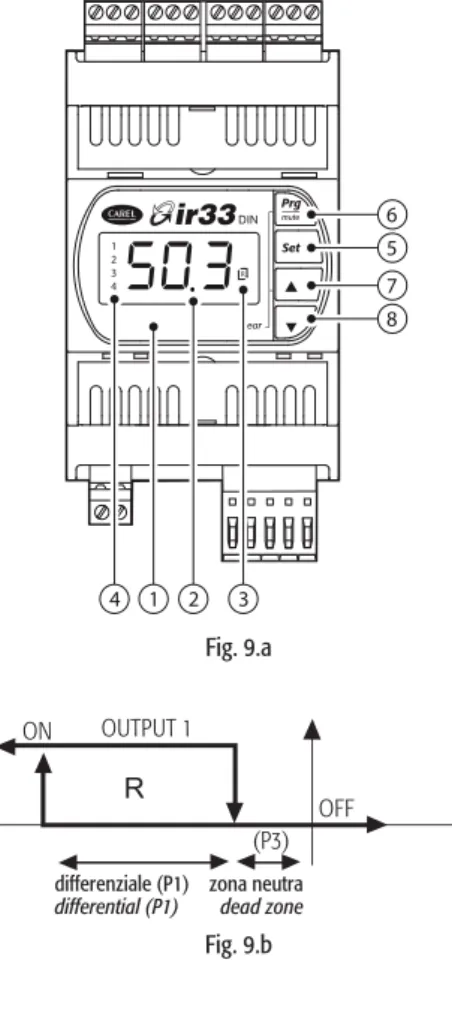
Important: make sure you use insulated wires with a minimum diameter of 1.5 mm2 for the electrical connections. Access to the humidifier junction box by removing the air fi lter, as described in chapter 6. In the case of alarms, the value read by the probe is displayed alternately with the code(s) of the active alarms.
Prg/mute button: pressed for 5 seconds, enters the menu of the most frequent parameters (code type "Pxx").
Setting the fundamental parameters
Alarms and troubleshooting
DIMENSIONS AND WEIGHTS 26
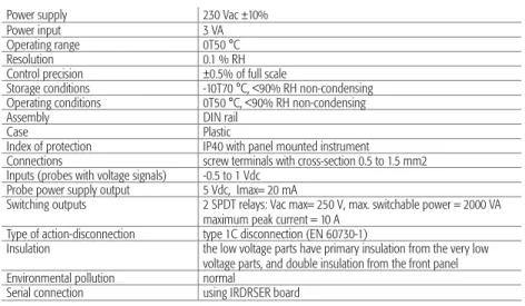
- Table of technical specifi cations for humiDisk 65
- Electrical specifi cations of electrical panels UCQ065D100
- Technical specifi cations of the CAREL DN33Z9HR20 humidistat
- Technical specifi cations of the UCHUMM0000 mechanical humidistat
- List of spare parts for humiDisk 10
- List of spare parts for humiDisk 65
Connections screw terminals with diameter 0.5 to 1.5 mm2 Inputs (probes with voltage signals) -0.5 to 1 Vdc. Insulation the low voltage parts have primary insulation from the very low voltage parts, and double insulation from the front panel. 11.d IMPORTANT NOTE: the cables used must be resistant to the maximum operating temperature, i.e. to the maximum room temperature specified, plus the heat produced by the controller, equivalent to 20°C with all the outputs on the maximum capacity.
TROUBLESHOOTING 30
Air comes out of the distributor, but not atomised water
The humidifi er continuously drains water