Safety precautions
Product features
3: “Hot Water Supply” on the AG-150A screen indicates Air To Water Booster unit group and Air To Water HEX unit group. Error The address of the faulty unit, error code and the address of the unit that detected the error will appear. This function is used to set unit name, ID number, LCD brightness, sound volume, date format, time format, temperature unit and display language.
This function is used to register indoor units, LOSSNAY units, remote controllers and lower level system controllers to a group. This function is used to make the basic settings for the floor layout and display position of the groups. Lower-level controller refers to a system controller that is controlled (including the units it controls) by a higher-level system controller.
Unit groups that are not under the control of the main controller and are managed by the subsystem controller. A subsystem controller that exceeds the main system controller's control range of two or more.
Component names and display screen names
The backlight turns on when the touchpad is touched and stays on while the user is using the touchpad. When an error occurs, the background turns on regardless of whether the user is using the touchpad. If nothing appears on the screen after touching the touch panel several times, the LCD backlight may be damaged.
User operation
The operation (ON/OFF) and error status of the air conditioner can be checked with the icons on the screen. If there is a device that cannot be identified, it will appear above the device icon. On the screen, detailed information about temperature, fan speed, air flow direction, ban/allow remote control status and status can be checked.
The operation (ON/OFF) and error status of the air conditioning units can be checked with the icons on the screen. If there is a device that cannot be identified, it will appear over the icon of the device. On the screen, detailed information about the temperature, fan speed, air flow direction, ban/allow status of the remote controller and mode can be checked.
Press the scroll button and to see the status of the rest of the blocks that are not displayed on the screen. An orange frame appears around the selected button. operating mode from one of the icons below. After making the selection, press the [Edit] button in the lower right corner of the screen to display the weekly schedule screen.
Select the days of the week on the weekly schedule setting screen and touch the schedule content button to open the schedule content setting screen. To copy the schedule from a particular day to another day, select the days of the week in the weekly schedule setting screen, touch [Copy] to select it, select a day to copy the schedule to want to copy and touch [Paste]. To copy the settings of the current daily schedule in one group to another, select the group in the current daily schedule settings screen (floor layout or block view screen), touch [Copy], select a group to which you want to transfer the schedule copy and tap [Paste].
Error code The error code of the error causing the error is displayed. Group name The name of the group containing the device whose filter character is switched on is displayed here. Device address The address of the devices with filter characters switched on is displayed here.
Floor name or Block name Group name The name of the group is displayed here. Date and time of error recovery The date and time of error recovery are shown here.
Initial Settings
Touch the [Unit Info.] tab on the screen that appears when you touch [Initial Settings] in the menu bar of the settings change window to open the Unit Info settings window and make basic settings for the AG-150A, such as are its name and display options. The unit ID entered here will be used on the software screen that controls multiple AG-150A units and for the sender ID in the error message. Touch the [Network] tab on the screen that appears when you touch [Initial Settings] on the menu bar of the change settings window to open the network settings window and perform basic settings for LAN and M-NET.
Enter the IP address on the keyboard that appears when you touch the IP address input button. Enter the subnet mask address for the AG-150A on the keyboard that appears when you touch the subnet mask input button. Press the group name input button and enter a group name that appears in 20 characters or less on the keyboard.
Touch the model selection button on the window that appears to display air conditioning units. In the [Monitor] section, select whether to display I/P to or from the general equipment on the monitor screen. Touch the block name button and enter the block name on the keyboard that appears in 20 characters or less.
Click on the group number to register in the group selection window that appears when the group button is tapped. To change the layout of the floor on the main operation screen or to change the display position of the groups on the floor, touch the [Floor layout] tab in the setting change window. When a floor is hidden, the icons on the floor will move to the bottom floor.
Press the floor name button on the basic floor settings window and enter the floor name in three characters or less. To view the list of refrigeration systems connected to AG-150A (connection information of outdoor and indoor units), touch [System View] on the window that appears when [Initial Settings] is touched on the setting change window and bring up the refrigerant system display window . Indoor unit The numbers assigned to the indoor units connected to the outdoor unit on the same row.
To move a group to another floor, first select the group to be moved in the floor layout settings window. To cancel, tap the climb button on the same floor as the cut button.
User Setting
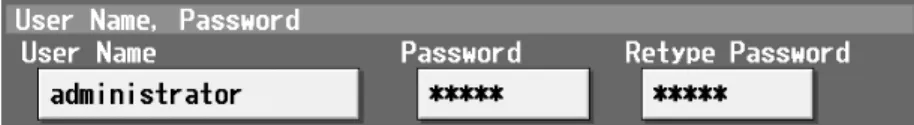
To change the name of the building manager, touch the enter username button and enter the username in the displayed keyboard in 20 characters or less. To change the building manager password, touch the enter password button and enter the password that is between 3 and 10 characters in the keyboard that appears. Tap the feature to activate the feature (An orange frame will appear around the selected item), or tap the selected item again to deselect it (no orange frame).
Group structure*1 Setting the connection of indoor units, remote controllers, system controllers and general equipment in a group. Block structure*1 Setting of registration of groups in the block Floor plan Floor name Setting of floor name.
Maintenance screen
To adjust the touch panel, touch [Maintenance] on the setting change screen and then touch [Touch Panel Calibration] to display the Touch Panel Calibration screen. A white "5 dots × 5 dots" square will appear on the screen in the following order: top left, top center, top right, middle left, center, middle right, bottom left, bottom center, and bottom right. When all nine squares are touched, the calibration is complete and the screen will return to the touch panel calibration screen.
If the screen is left untouched for one minute, the screen will automatically return to the calibration screen and this step must be started all over again.
Cleaning the touch panel
External input/output function
The “ON” signal is output when one or more air conditioners are in ON mode. When using the LAN connection function, connect the LAN cable to the LAN terminal of this machine. While the emergency stop is ON, operation from both the controller and the local remote control (ON/OFF only) is prohibited.
After the emergency shutdown is canceled, the air conditioning units will remain turned off and will require manual operation if they need to be restarted. When level signals are used for ON/OFF, operation from both the controller and the local remote control (ON/OFF only) is prohibited at all times. If the control signal is received during operation, air conditioning units continue to operate.
When pulse signals are used, the remote controller will prohibit changing ON/OFF, operation mode, temperature setting, filter sign setting reset.