It covers the main hydraulic components; available in several configurations with high or low static pressure, single pump or backup pump (see configurator). 02 Tank | low static pressure pump | backup pump | system page 03 Inventory | high static pressure pump | side of the system. 06 Tank with holes for integrative resistance | low static pressure pump | backup pump | system page 07 Hole stock for integrative resistor | high static pressure pump | side of the system.
08 Storage tank with holes for integrative resistance | high static pressure pump | spare pump | system side P1 Low static pressure pump | the system side. P4 High static pressure pump | spare pump | system side 15,16 DHW SIDE HYDRONIC KIT 2. R1 Low static pressure pump | The hot water side. 1 System side heat exchanger 2 Hot water side heat exchanger 3 Source side heat exchanger AL Liquid tank CV One-way valve.
1 System side heat exchanger 2 DHW side heat exchanger 3 Source side heat exchanger AL Liquid storage tank CV One-way valve F Dehydrator filter. 1 System side heat exchanger 2 DHW side heat exchanger 3 Source side heat exchanger AL Liquid storage tank CV One-way valve.
HOT WATER PRODUCTION ONLY TO SYSTEM
SIMULTANEOUS HOT AND COLD WATER PRODUCTION TO SYSTEM
DESCRIPTION OF COMPONENTS 1. COOLING CIRCUIT
- WATER FEATURES
- STRUCTURE AND FANS
- STANDARD HYDRAULIC CIRCUIT
- COMPONENTS OF HYDRAULIC CIRCUIT IN CONFIGURABLE VERSIONS
- SAFETY AND CONTROL COMPONENTS
- ELECTRIC CONTROL AND POWER BOARDAND POWER BOARD
Equipped with a steel filtering net, the heat exchangers prevent both on the system side and the hot water/. Equipped with a pipe outlet, intervenes by discharging the excess pressure in case of abnormal pressure. MANUAL RESET HIGH PRESSURE SWITCH With fixed calibration, located on the high pressure side of the refrigeration circuit, prevents the operation of the compressor if abnormal working pressure occurs.
It is placed on the low pressure side of the refrigeration circuit and indicates the working pressure to the control board and generates an advance warning in case of abnormal pressure. Placed on the high pressure side of the cooling circuit, it indicates the working pressure to the control board and generates an advance warning in the event of abnormal pressure. It consists of an adjustment circuit board that varies the number of fan revolutions according to the condensing pressure read by the high pressure transducer, to keep it sufficiently high for correct unit functioning.
It also allows correct functioning in heating mode with external temperatures above 30°C and up to 42°C. This lever can be locked with one or more padlocks during maintenance interventions to prevent the machine from being switched on accidentally.
ACCESSORIES
MECHANICAL ACCESSORIES
ELECTRIC ACCESSORIES
TECHNICAL DATA
Aermec determines the sound power values in accordance with the EN ISO 9614-2 standard, in accordance with that required by the Eurovent certification. Sound pressure measured in free field conditions with a reflective surface (directivity factor Q=2) at a distance of 10 mt from the external surface of the unit, in accordance with EN ISO 3744 regulations.
OPERATIONAL LIMITS
COOLING MODE¹
HEATING MODE ¹
CORRECTIVE FACTORS FOR DATA DIFFERENT THAN NOMINAL IN COOLING MODE 1. YIELDS AND ABSORPTION DIFFERENT THAN NOMINAL
CORRECTIVE FACTORS FOR DATA DIFFERENT THAN NOMINAL IN HEATING MODE
CORRECTIVE COEFFICIENTS OF RECOVERED HEATING CAPACITY
IN FUNCTIONING MODE WITH DHW SIDE RECOVERY 2 PIPES | HOT WATER PRODUCTION SYSTEM SIDE 4 PIPES
HOT WATER PRODUCTION SYSTEM INSIDE 2 PIPES
USEFUL STATIC PRESSURES 2|4 PIPE SYSTEM
- HIGH STATIC PRESSURE PUMPS IN COOLING MODE SYSTEM SIDE
- LOW STATIC PRESSURE PUMPS DHW SIDE 2 PIPES | HEATING SIDE 4 PIPES
- HIGH STATIC PRESSURE PUMPS DHW SIDE 2 PIPES | HEATING SIDE 4 PIPES kPa
- HOW TO INTERPRET GLYCOL CURVES The curves shown in the diagram summarise The curves shown in the diagram summarise
Cooling capacity and power input correction factors take into account the presence of glycol and the change in evaporation temperatures. The corrected pressure drop factor takes into account the different flow rate resulting from applying the correct water flow rate to the factor. The water flow rate, factored in, is calculated to maintain the same Δt that would be present in the absence of glycol.
To determine the required percentage of glycol, see the diagram below; this percentage calculation may take into account one of the following factors. Depending on which fluid is considered (water or air), the graph is interpreted from the right or left side at the point of intersection of the curves with the external temperature line or the line produced by water. A point is obtained through which the vertical line will pass and this will distinguish both the percentage of glycol and the relative correction coefficients.
HOW TO INTERPRET THE GLYCOL CURVES The curves shown in the chart summarize The curves shown in the chart summarize The curves shown in the chart summarize a significant amount of data, each represented by a specific curve . To use these curves correctly, it is first necessary to make some initial reflections. If you want to calculate the percentage of glycol based on the outside air temperature, enter from the left axis and when you reach the curve, draw a vertical line, which in turn will intercept all other curves; the points obtained from the upper curves represent the coefficients for the correction of the cooling capacity and the input power, the flow rates and the pressure drops (remember that these coefficients must be multiplied by the nominal value of the relevant size op); while the recommended glycol percentage value to produce the desired water temperature is on the lower axis.
To calculate the percentage of glycol based on the produced water temperature, enter from the right axis and when you reach the curve, draw a vertical line that will intercept all the other curves; the points obtained on the above curves represent coefficients for the correction of cooling capacity and power input, flow rates and pressure drops (remember that these coefficients must be multiplied by the nominal value of the size in ques). on); while the lower axis recommends the value of the percentage of glycol required to produce water at the desired temperature.
ETHYLENE GLYCOL SOLUTIONS
EXPANSION VESSEL CALIBRATION
The standard preload pressure value for the expansion tank is 1.5 bar, while the volume is 24 liters. For example: if the level difference (H) is equal to 20 m, the calibration value of the vessel will be 2.3 bar. If the calibration value obtained from the formula is less than 1.5 bar (ie for H < 12.25), keep the calibration as standard.
EXPANSION VESSEL CALIBRATION
MINIMUM WATER CONTENT
PARTIALISATIONS
SOUND DATA
CALIBRATIONS OF SAFETY AND CONTROL PARAMETERS
GENERAL WARNINGS
PRESERVATION OF THE DOCUMENTATION The instructions along with all the related
INSTALLATION
WARRANTY
WARNINGS REGARDING SAFETY AND INSTALLATION STANDARDS INSTALLATION STANDARDS
PRODUCT IDENTIFICATION
ISO DIS 9614/2 intensimetric method
RECEIPT OF THE PRODUCT AND INSTALLATION 1. RECEIPT AND HANDLING
HANDLING THE MACHINE
- LIFTING STANDARDS
SELECTION AND PLACE OF INSTALLATION
WEIGHT OF UNITS WHEN EMPTY
WEIGHT OF UNITS WHEN RUNNING
- NRP0300 0330 0350
- NRP 0500 0550 0600 0650
- NRP 0700
- NRP 0750
- POSITION OF HYDRAULIC CONNECTIONS
- BASIC 2 PIPE SYSTEM HYDRAULIC CIRCUITS
- CIRCUITO IDRAULICO INTERNO ED ESTERNO AD NRP “°” standard
The unit is delivered mounted on a pallet; use sticks (not included) for moving with forklifts and straps. The unit is delivered mounted on a pallet; use sticks (not included) for moving with forklifts and straps. The unit is delivered packaged in estincoil; it must be lifted using suitable straps hooked to all installed eyebolts.
The selection and installation of components outside the PRK unit is the responsibility of the installer, who must operate according to the code of practice and in accordance with the Standard in force in the country of destination. The hydraulic connection pipes to the machine must be sized appropriately for the effective water flow rate required by the system when operating. The connecting pipe must be adequately supported so that its weight is not borne by the equipment.
A suitable charging/reintegration system should be provided, which is connected to the return line, together with a drain cock at the lowest part of the system.
NRP HYDRAULIC
COMPONENTS RECOMMENDED HYDRAULIC COMPONENTS EXTERNAL TO UNIT
INTERNAL AND EXTERNAL HYDRAULIC CIRCUIT TO NRP “01…08” with system storage tank only
Electrical conductivity Less than 200 mV/cm (25°C) Chloride ions Less than 50 ppm Sulfuric acid ions Less than 50 ppm Total iron Less than 0.3 ppm.
COMPONENTS RECOMMENDED HYDRAULIC COMPONENTS
- BASIC 4 PIPE SYSTEM HYDRAULIC CIRCUITS
- INTERNAL AND EXTERNAL HYDRAULIC CIRCUIT TO NRP “°” standard
- INTERNAL AND EXTERNAL HYDRAULIC CIRCUIT TO NRP “01…08” with cooling system side storage tank only
- INTERNAL AND EXTERNAL HYDRAULIC CIRCUIT TO NRP “P1…P4 R1…R4” with pumps on COOLING and HEATING sideCOOLING and HEATING side
- LOADING SYSTEM
- DISCHARGING SYSTEM
- COLLEGAMENTI ELETTRICI
- ELECTRIC DATA TABLE
- PREPARATION FOR COMMISSIONING
- START UP
- MACHINE COMMISSIONING
- ELECTRIC POWER CONNECTION TO THE ELECTRICAL MAINS
- CONTROL AND COMMISSIONING
- WITH THE MACHINE ON, CHECK COOLING CIRCUIT
- FUNCTIONING FEATURES
- SET POINT IN COOLING MODE
- SET POINT IN HEATING MODE
- COMPRESSOR START UP DELAY
- CIRCULATION PUMPS NOT SUPPLIED
- ANTI FREEZE ALARM
- WATER FLOW RATE ALARM
- SWITCH ON AND USE OF UNIT
- MENU STRUCTURE
- seconds have passed, it will no longer be possible to modify
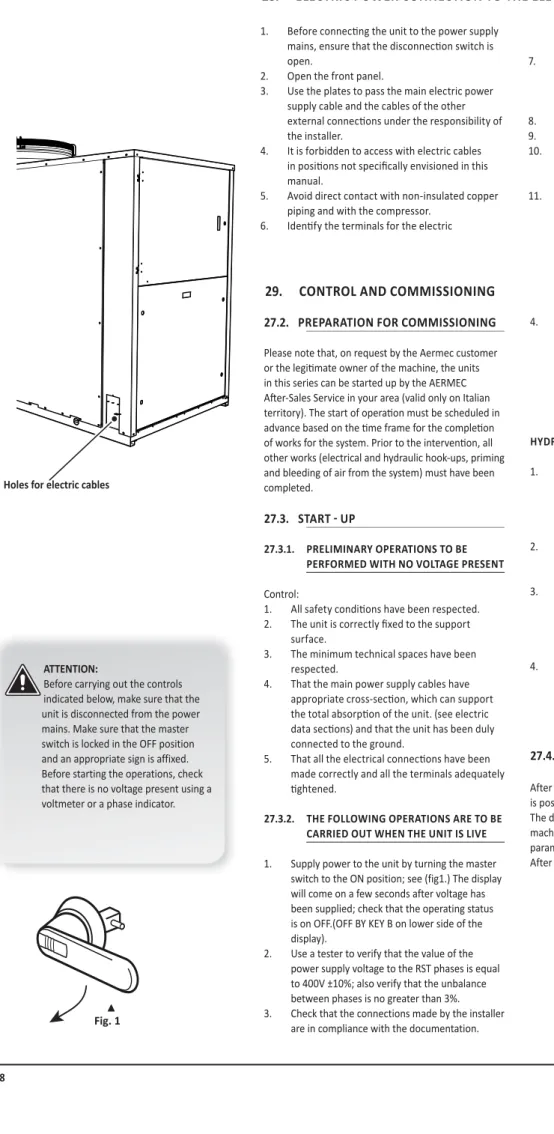
10% of the nominal power supply voltage of the machine (in case of unbalanced three-phase unit max. 3% between phases). The use of an omnipolar magnetic switch is mandatory in accordance with the IEC-EN standards (contact opening of at least 3 mm), with appropriate interrupting power and differential protection based on the electrical data table shown below, installed as close to the appliance as possible. To get the functional connection of the device, take the power supply cable to the electrical control board inside the device and connect it to the terminals L1-L2-L3 and PE according to the polarities.
That the main power supply cables have a suitable cross-section which can support the total absorption of the unit. see electrical data sections) and that the unit is properly earthed. Use a tester to verify that the power supply voltage value on the RST phases is equal to 400V ±10%; also verify that the unbalance between phases is not greater than 3%. Verify that the compressor casing resistance is working by measuring the temperature rise of the oil pan.
The resistor/s must function for at least 12 hours before starting the compressor and in any case the temperature of the oil pan must be 10-15°C higher than room temperature. Ensure that the circulation pump/s is operating and that the water flow rate is sufficient to close the contact of the flow switch. Check the correct operation of the flow meters, if installed; when the cut-off valve at the outlet of the heat exchanger is closed, the unit should display the block.
Pressure line temperature If the subcooling and superheating values are regular, the temperature measured in the pressure line pipe at the outlet of the compressor should be 30/40°C above the condensing temperature. The anti-freeze control managed by the electronic regulation and the temperature probe located at the evaporator outlet is to prevent the formation of ice when the water flow rate is too low. To prevent the heat exchanger from breaking due to the freezing of the water it contains, foresee the blocking of the compressor (if the machine is below 3.5°C) and the ignition of the resistance (if in standby below 5°C).
If the temperature detected by the probe located at the outlet of the heat exchanger and at the inlet to the cooler is less than +3.8°C. The intervention of this alarm determines the compressor block and not the pump block, which remains active together with the ignition of the resistor if installed. The control panel of the NRP unit allows quick setting of machine operation parameters and their display.
MENU STRUCTURE
ACCESSORY CONNECTIONS
