After stopping the operation of the air conditioner, turn off the power supply switch and remove the power plug. When the repair or inspection of the circuit must be done without turning off the power, be very careful not to touch the live parts. It may cause an explosion, explosion or fire when the device is used, serviced or disposed of.
Correct refrigerant is specified in the manuals and on the specifications supplied with our products.
OBH626L
NOISE CRITERIA CURVES
MXZ-2D53VA MXZ-2D53VA2
MXZ-2D42VA MXZ-2D42VA2
MXZ-2D40VA
MXZ-3D54VA
OUTLINES AND DIMENSIONS
MXZ-3D54VA MXZ-3D54VA2 MXZ-3D68VA
MXZ-4D72VA
MXZ-6D122VA
1.FREE SPACE
2.SERVICE SPACE
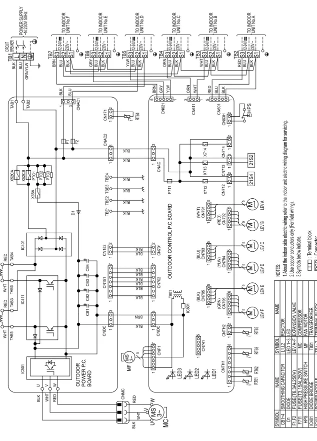
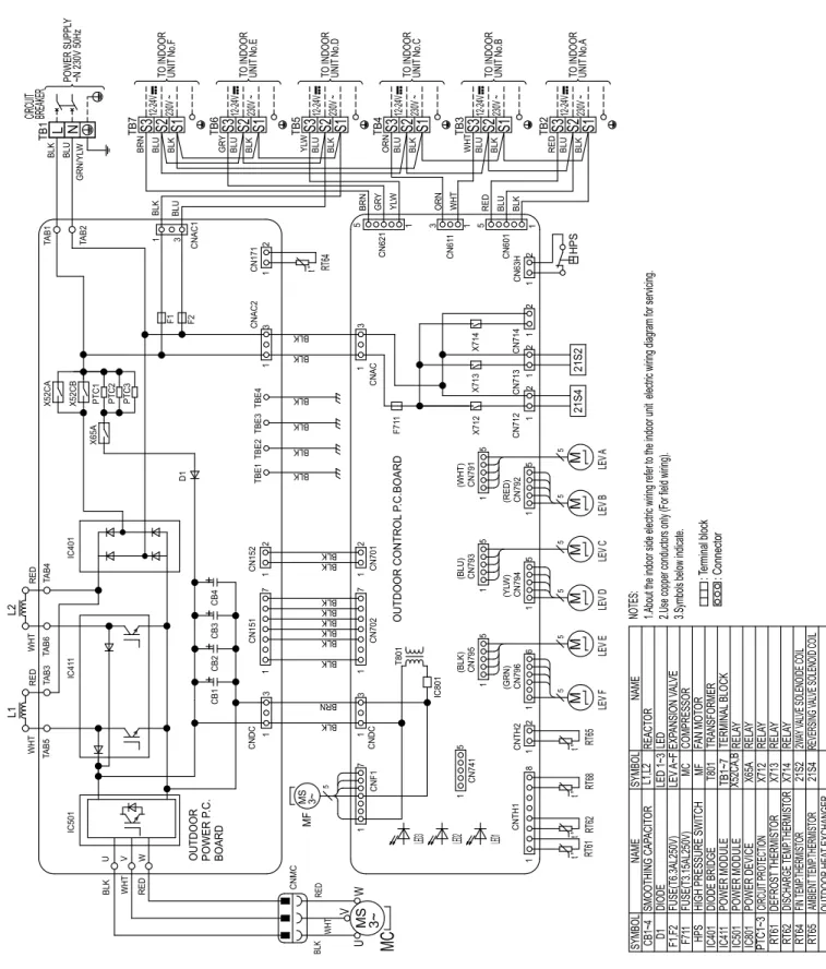
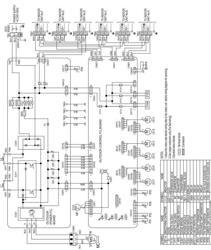
WIRING DIAGRAM
About the indoor electrical wiring, refer to the indoor unit electrical wiring diagram for service. DIODE MODULE FUSE (T3.15AL250V) FUSE (T3.15AL250V) POWER MODULE POWER DEVICE LED OUTDOOR HEAT EXCHANGER TEMP.
MXZ-2D53VAH - E1
MXZ-2D53VAH - E2
MXZ-2D53VAH - E3
MXZ-2D53VAH - ER2
MXZ-2D53VAH - ER3
MXZ-2D53VAH2 - E3
MXZ-3D54VA - E1
MXZ-3D54VA2 - E2
MXZ-3D54VA2 - E3
MXZ-3D54VA2 - ER2
MXZ-3D54VA2 - ER3
MXZ-3D54VA2 - ET2
MXZ-3D54VA2 - ET3
MXZ-3D68VA - E1
MXZ-3D68VA - E2
MXZ-3D68VA - E3
MXZ-3D68VA - ER2
MXZ-3D68VA - ER3
MXZ-3D68VA - ET2
MXZ-3D68VA - ET3
MXZ-4D72VA - E1
MXZ-4D72VA - E2
MXZ-4D72VA - E3
MXZ-4D72VA - ER2
MXZ-4D72VA - ER3
MXZ-4D72VA - ET2
MXZ-4D72VA - ET3
MXZ-4D83VA - E1
MXZ-4D83VA - E2
MXZ-4D83VA - ER1
MXZ-4D83VA - ER2
MXZ-4D83VA - ET2
MXZ-5D102VA - E1
MXZ-5D102VA - E2
MXZ-5D102VA - ER1
MXZ-5D102VA - ER2
MXZ-5D102VA - ET2
MXZ-6D122VA - E1
MXZ-6D122VA - ER1
MXZ-6D122VA - ET1
MXZ-6D122VA - E2
MXZ-6D122VA - ER2
MXZ-6D122VA - ET2
REFRIGERANT SYSTEM DIAGRAM
MXZ-2D33VA
MAX REFRIGERANT PIPING LENGTH
ADDITIONAL REFRIGERANT CHARGE
MXZ-2D42VA MXZ-2D42VA2 MXZ-2D53VA MXZ-2D53VA2 MXZ-2D53VAH MXZ-2D53VAH2
MXZ-3D54VA MXZ-3D54VA2
MXZ-3D68VA
If the diameter of the refrigerant piping is different from that of the outdoor unit connection, use the optional piping with a different diameter.
MXZ-4D83VA
MXZ-5D102VA
When the air conditioner is moved or disposed of, pump down the system according to the procedure below so that no refrigerant is released into the atmosphere. If too much refrigerant has been added to the air conditioner system, the pressure may not drop to 0.05 to 0 MPa [meter]. about 0.5 to 0 kgf/cm²), or the protection function can operate due to the pressure increase in the high-pressure refrigerant circuit. If this happens, use a refrigerant collection device to collect all the refrigerant in the system, then recharge the system with the correct amount of refrigerant after moving the indoor and outdoor units.
The compressor may burst and cause injury if a foreign substance, such as air, enters the piping.
PUMPING DOWN
PERFORMANCE CURVES
2) AIR FLOW
3) MAIN READINGS
How to measure the indoor air wet and dry bulb temperature difference
MXZ-4D72VA MXZ-4D83VA MXZ-5D102VA MXZ-6D122VA
8-1. CAPACITY AND THE INPUT CURVES
MXZ-3D54VA MXZ-3D54VA2 MXZ-3D68VA MXZ-4D72VA
MXZ-4D83VA MXZ-5D102VA
15-class unit
20-class unit
22-class unit
25-class unit 18-class unit
25-class unitMXZ-2D40VA
18-class unit
35-class unitMXZ-2D40VA
25-class unit
35-class unit
42-class unit
50-class unit
MXZ-2D42VA MXZ-2D42VA2 MXZ-2D53VA MXZ-2D53VA2 MXZ-2D53VAH MXZ-2D53VAH2
MXZ-3D54VA MXZ-3D54VA2 15-class unit
22-class unit 18-class unit
MXZ-3D54VA MXZ-3D54VA2
MXZ-3D68VA 15-class unit
25-class unit 20-class unit
MXZ-3D68VA 35-class unit
60-class unit
71-class unit 35-class unit
Press the EMERGENCY OPERATION switch to start COOL or HEAT mode (COOL: press once, HEAT: press twice). To cancel test run or EMERGENCY OPERATION, press the EMERGENCY switch or any button on the remote controller.
1) COOL operation
MXZ-2D33VA 15-class unit
MXZ-2D40VA 15-class unit
MXZ-3D68VA MXZ-4D72VA
MXZ-3D68VA MXZ-4D72VA 20-class unit
MXZ-4D83VA 15-class unit
71-class unit
MXZ-5D102VA 15-class unit
25-class unit 22-class unit
2) HEAT operation
15-class unit 20-class unit 22-class unit
35-class unit 42-class unit
50-class unit 15-class unit 20-class unit 22-class unit
25-class unit 35-class unitMXZ-3D54VA MXZ-3D54VA2
42-class unit 50-class unit
25-class unit 35-class unitMXZ-3D68VA MXZ-4D72VA
60-class unitMXZ-4D83VA
22-class unit 20-class unit
60-class unit 71-class unit
MXZ-6D122VA 15-class unit
ACTUATOR CONTROL
Relation between main sensor and actuator
SERVICE FUNCTIONS
10-1. THE POSITION OF SWITCH
SW1 on the outdoor control P.C. board
10-3. LOWERING THE OPERATING NOISE OF THE OUTDOOR UNIT
10-4. AUTOMATIC LINE CORRECTING
Improper wiring or piping can be automatically detected by pressing the wiring/wiring correction switch (SW871) on the external control computer. When faulty wiring or piping is found, the wiring is repaired. This function does not work if the outside temperature is not higher than 0ºC.) 2. Check that the shut-off valves of the liquid and gas pipes are open. On Off On Completed (Trouble Fixed/Normal) Once Once Once Not Completed (Detection Failed).
Make sure the valves are open and the lines are not collapsed or clogged. When this function is activated while the indoor unit is operating, the operation is stopped. Activate this function to check the correct wiring after replacing the outdoor PC. Previous records are cleared when the outdoor control P.C. board has been replaced).
The record cannot be displayed if the automatic line correction is not canceled (see "How to activate this function").
If moisture enters the refrigerant circuit or when refrigerant liquefies and collects in the compressor. it can interfere with starting the compressor. To improve the start-up condition, the compressor is activated even when it is not operating to generate heat at the winding. NOTE: The preheat control will be turned OFF when the power supply is turned off.
SW2 on the outdoor display P.C. board
SW2 on the outdoor control P.C. board
SW2 on the external controller P.C. 1) Be sure to turn off the main power of the air conditioner before making the adjustment.
11 TROUBLESHOOTING
Troubleshooting procedure
Take care of the following during servicing
11-2. FAILURE MODE RECALL FUNCTION
Flow chart of the detailed outdoor unit failure mode recall function
No light No light — — —. 2 times flash External power system On On Overload protection cut-out operates 3 times consecutively within 1 minute after compressor start. 8 times flash Outdoor fan motor light light The error occurs 3 times consecutively within 30 seconds after the fan starts. 10 times flash Discharge temperature Steady Steady Discharge temperature is maintained below 50°C (COOL mode)/40°C (HEAT mode) for more than 40 minutes.
Check the connection wire between the external control computer. Check the connection wire between the control computer. Check the voltage of the power supply. 2-time flash External power system light on Overvoltage protection cut-off operates 3 times consecutively within 1 minute after compressor start-up or inverter protective cut-off or bus voltage cut-off operates 3 times consecutive times within 3 minutes after start-up. 6 times flash High pressure lights on The external temperature of the heat exchanger exceeds 70 °C during cooling or the internal temperature of the gas pipe exceeds 70 °C during heating.
15-times fl as LEV and drain pump Illuminated Illuminated The indoor unit detects an abnormality.
11-3. INSTRUCTION OF TROUBLESHOOTING
A short circuit is detected in the thermistor during operation or when an open circuit is detected in the thermistor after 5 minutes (for cooling) and 10 minutes (for heating) after starting the compressor. A short circuit is detected in the thermistor during operation or when an open circuit is detected in the thermistor after 5 minutes after starting the compressor. A short circuit is detected in the thermistor during operation or when an open circuit is detected in the thermistor after 10 minutes after starting the compressor.
A short circuit is detected in the thermistor during operation, or an open circuit is detected in the thermistor 5 minutes (in cooling) and 10 minutes (in heating) after starting the compressor. A short circuit is detected in the thermistor during operation, or an open circuit is detected in the thermistor 5 minutes after starting the compressor. A short circuit is detected in the thermistor during operation, or an open circuit is detected in the thermistor 10 minutes after starting the compressor.
A short or open circuit is detected in the current sensor while the compressor is operating. Once illuminated LEV and drain pump The indoor unit detects an abnormality in the LEV. A short circuit is detected in the thermistor during operation, or an open circuit is detected in the.
A short circuit is detected in the thermistor during operation, or an open circuit is detected in the thermistor after 5 minutes (in cooling) and 10 minutes (in heating) of starting the compressor. Fusing Thermistor A short circuit is detected in the thermistor during operation or an open circuit is detected in the thermistor after 5 minutes of starting the compressor.
11-5. TROUBLE CRITERION OF MAIN PARTS
11-6. TROUBLESHOOTING FLOW
Is there faulty wiring, poor contact or disconnection of the internal/external connecting wire. Check the intermediate connection of the inner/outer connecting wire, the loose connection with the terminal block and cut the wire inside the cable. If the problem occurs or not depending on whether the light is on or off, move the light away from the indoor unit or install a glass filter on the receiving part of the indoor unit.
How to check miswiring and serial signal error (when outdoor unit does not work)
MXZ-2D/3D/4D/5D
Reroute the indoor/outdoor jumper wire if the existing wiring is done as below:. The indoor/outdoor connecting wire is diverted and runs long. indoor/outdoor connecting wire from the outdoor terminal block connected to the indoor unit indicating incorrect wiring or serial signal error. Is there an error in the indoor/outdoor connection wire, such as wire damage, intermediate connection, poor contact with the terminal block.
Disconnect the connector (CNMC) between the inverter P.C. card and compressor, or disconnect the compressor terminal. Turn off the power supply and measure the compressor winding resistance between the compressor terminals. After the outdoor fan starts running, wait for 1 minute or more before measuring the voltage.
No Turn on the power supply of the outdoor unit after checking that the LEV coil is well mounted on the LEV body.
MXZ-4D83VA/5D102VA
Turn on the power supply to start the operation and measure the voltage of connector CN931. Turn ON the power supply and measure the voltage of connector CN931 while turning the motor by hand. Switch on the power supply to start the operation and measure the voltage of connector CNF1.
Turn on the power supply and measure the voltage of the CNF1 connector while turning the motor by hand.
MXZ-2D33VA/2D40VA/2D42VA/2D42VA2/2D53VA/2D53VA2
Turn OFF the power supply of the indoor and outdoor unit and disconnect connector CN781.
MXZ-3D54VA/3D54VA2/3D68VA/4D72VA MXZ-4D83VA/5D102VA
LED1 indicator lamp conf rm on external control P.C. Flash 9 times Replace external control P.C. Turn off the power supply before removing the PC. LED1 indicator lamp conf rm on external control P.C. Turn on the power supply. When you try to operate 2 indoor units simultaneously, one for cooling and one for heating, the unit that transmits the signal to the outdoor unit first sets the operation mode. When the above situation occurs, set all the indoor units to the same mode, turn OFF the indoor units, and then turn them back.
Although the top of the indoor unit sometimes becomes warm, this does not indicate a malfunction. The reason is that the refrigerant gas flows continuously into the indoor unit even when it is not operating.
Check of outdoor refrigerant circuit Has the operation stopped
Inverter P.C. board
CN796 LEV F
Outdoor display P.C. board
Noise filter P.C. board
MXZ-4D83VA MXZ-5D102VA
OPERATING PROCEDURE PHOTOS
DISASSEMBLY INSTRUCTIONS
- Removing the R.V. coil
- Removing the cabinet and the panels
- Removing the reactor
- Removing the expansion valve (1) Remove the service panel (Photo 1)
- Removing the panels
- Removing the compressor and the 4-way valve (1) Remove the service panel (Photo 1)
- Removing the fan motor
- Removing the compressor and 4-way valve
- Removing the expansion valve
External power screws P.C. board and noise filter P.C. 3) Disconnect all connectors and lead wires at the external control P.C. 5) Remove the screws securing the external P.C. 6) Disconnect all connectors and lead wires on the external P.C. board and lift it up. Rear panel screws Top panel screws Photo 2. Side panel screws Photo 3. 1) Remove the service panel, top panel and front panel (Photo 1). Rear panel screws Photo 2. Front panel screws Rear panel screws. board, reactor and external power P.C. tor board and external power P.C. 1) Remove the service panel, top panel and front panel (Refer to 1).
OBH626L 179
MXZ-2D33VA COOLING
MXZ-2D33VA HEATING
MXZ-2D40VA COOLING
MXZ-2D40VA HEATING
MXZ-2D42VA/MXZ-2D42VA2 COOLING
MXZ-2D42VA/MXZ-2D42VA2 HEATING
MXZ-2D53VA(H)/MXZ-2D53VA(H)2 COOLING
MXZ-2D53VA(H)/MXZ-2D53VA(H)2 HEATING
MXZ-3D54VA COOLING
MXZ-3D54VA HEATING
MXZ-3D54VA2 COOLING