Installation Manual IM 1002
Pathfinder™ Air Cooled Chillers
Group: ChillersPart Number:
10000199902
Date: June 11, 2009
© 2009 McQuay International
Models AWS 280ADS to AWS 300ADS (Standard Efficiency) Models AWS 300ADH to AWS 360ADH (High Efficiency) 280 to 350 Tons, 985 to 1230 kW
R-134a
50 Hz
Contents
Introduction . . . 3
Installation and Startup . . . 4
Handling . . . 4
Location. . . 4
Service Access . . . 4
Clearance Requirements . . . 5
Restricted Air Flow . . . 6
Chilled Water. . . 9
Water Piping . . . 9
System Water Volume . . . 9
Variable Speed Pumping . . . 9
Evaporator Freeze Protection . . . 10
Flow Switch . . . 10
Performance Adjustment Factors . . . 11
Physical Data. . . 13
Dimensions . . . 15
Lifting & Mounting Weights . . . 20
Lifting and Mounting Locations . . . 21
Isolator Locations and Kit Numbers . . . 24
Electrical Data . . . 26
Wiring Diagram . . . 30
Troubleshooting Chart . . . 33
Hazard Identification
©2009 McQuay International. Illustrations and data cover the McQuay International product at the time of publication and we reserve the right to make changes in design and construction at anytime without notice. ™® The following are trademarks or registered trademarks of their respective companies: BACnet from ASHRAE;
LONMARK, LonTalk, LONWORKS, and the LONMARK logo are managed, granted and used by LONMARK International under a license granted by Echelon Corporation; ElectroFin from AST ElectroFin Inc.; Modbus from Schneider Electric; FanTrol, MicroTech III, Open Choices, and SpeedTrol from McQuay International
DANGER
Dangers indicate a hazardous situation which will result in death or serious injury if not avoided.
WARNING
Warnings indicate potentially hazardous situations, which can result in property damage, severe personal injury, or death if not avoided.
CAUTION
Cautions indicate potentially hazardous situations, which can result in personal injury or equipment damage if not avoided.
Document: IM 1002 Issue Date: June 2009 Revision Date: June 11, 2009 Replaces: June 1, 2009
Modbus
Introduction
Introduction
Figure 1: Model Nomenclature
General Description
Daikin McQuay Pathfinder™ air-cooled chillers are complete, self-contained chillers that include the latest in engineered components arranged to provide a compact and efficient unit.
Each unit is completely assembled, factory wired, evacuated, charged, tested and comes complete and ready for installation.
Each of two circuits consists of an air-cooled condenser section with an integral subcooler section, a semi-hermetic, single-screw compressor with starter, a multi-circuit, shell- and-tube, direct expansion evaporator, an economizer and complete refrigerant piping. Each compressor has an independent refrigeration circuit. Liquid line components included are a manual liquid line shutoff valve, charging port, filter-drier, sight-glass/moisture indicator, and electronic expansion valve. A combination discharge check and shutoff valve is included and a compressor suction shutoff valve is optional. Other features include compressor heaters, evaporator heaters for freeze protection, automatic, one-time pumpdown of each refrigerant circuit upon circuit shutdown, and an advanced fully integrated microprocessor control system.
Pathfinder units are available as standard efficiency (ADS) or high efficiency (ADH)
A high ambient option is required for operation in ambient temperatures above 105F (40.6C) and up to 125F (51.7C) and when the VFD low ambient option is selected.
Information on the operation of the unit MicroTechIII controller is in the OM 998 manual.
Inspection
When the equipment is received, carefully check all items against the bill of lading to verify for a complete shipment.
Check all units for damage upon arrival. All shipping damage must be reported to the carrier and a claim must be filed with the carrier. Check the unit’s serial plate before unloading the unit to be sure that it agrees with the power supply available.
Physical damage to a unit after shipment is not McQuay International’s responsibility.
Note: Unit shipping and operating weights are shown in the Physical Data Tables beginning on page 13.
S = Standard Efficiency H = High Efficiency A W S XXX A D S
Air-Cooled World Product Screw Compressor Nominal Tons
Dual Compressor Design Vintage
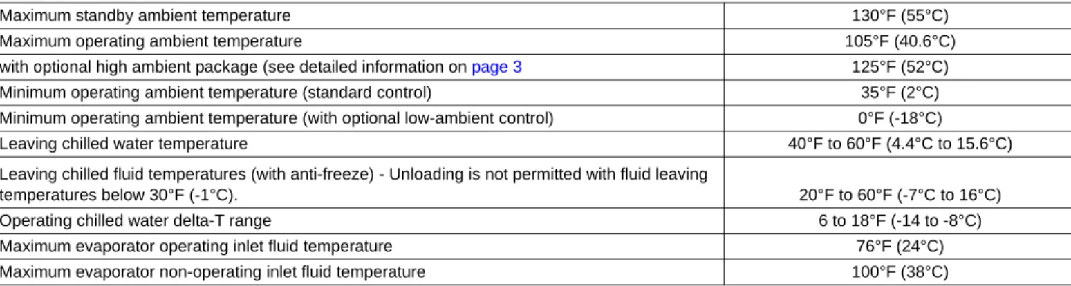
Table 1: Operating Limits
Maximum standby ambient temperature 130°F (55°C)
Maximum operating ambient temperature 105°F (40.6°C)
with optional high ambient package (see detailed information on page 3 125°F (52°C)
Minimum operating ambient temperature (standard control) 35°F (2°C)
Minimum operating ambient temperature (with optional low-ambient control) 0°F (-18°C)
Leaving chilled water temperature 40°F to 60°F (4.4°C to 15.6°C)
Leaving chilled fluid temperatures (with anti-freeze) - Unloading is not permitted with fluid leaving
temperatures below 30°F (-1°C). 20°F to 60°F (-7°C to 16°C)
Operating chilled water delta-T range 6 to 18°F (-14 to -8°C)
Maximum evaporator operating inlet fluid temperature 76°F (24°C)
Maximum evaporator non-operating inlet fluid temperature 100°F (38°C)
Installation and Startup
Installation and Startup
Installation and maintenance are to be performed only by qualified personnel who are familiar with local codes and regulations, and experienced with this type of equipment.
Start-up by McQuay Factory Service is included on all Pathfinder units sold for installation within the U.S. and Canada and must be performed by them to initiate the standard Limited Product Warranty. Start-up by any party other than McQuay Factory Service or a McQuay Authorized Service Representative will void the Limited Product Warranty. Two- week prior notification of start-up is required. The contractor should obtain a copy of the Start-up Scheduled Request Form from the sales representative or from the nearest McQuay Factory Service office.
Handling
Avoid rough handling shock due to impact or dropping the unit. Do not push or pull the unit. Never allow any part of the unit to fall during unloading or moving, as this can result in serious damage.
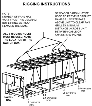
To lift the unit, lifting tabs with 3" (76 mm) diameter holes are provided on the base of the unit. All lifting holes must be used when lifting the unit. Spreader bars and cables should be arranged to prevent damage to the condenser coils or unit cabinet (see Figure 2).
Location
Locate the unit carefully to provide proper airflow to the condenser. (SeeFigure 4, page 5 for required clearances.)Using less clearance than shown in Figure 4can cause discharge air recirculation to the condenser and could have a significant detrimental effect on unit performance.
Due to the shape of the condenser coils on the Pathfinder chillers, it is recommended that the unit be oriented so that prevailing winds blow parallel to the unit length, thus minimizing the wind effect on condensing pressure and performance. If low ambient temperature operation is
expected, optional louvers should be installed if the unit has no protection against prevailing winds.
For pad-mounted units, it is recommended that the unit be raised a few inches with suitable supports such as neoprene waffle vibration pads, located at least under the mounting locations. This will allow water to drain from under the unit and facilitate cleaning under it.
Figure 2: Required Lifting Method
NOTES:
1. Unit with 8 lifting points illustrated above; the number of condenser sections, fans, and lifting points can vary from this diagram.see lifting/mounting drawings beginning on page page 41 to identfy the number of lifting points for a specific unit.
2. All rigging points must be used. See weights at lifting points beginning on page 39 for each specific size unit.
3. Crosswise and lengthwise spreader bars must be used to avoid damage to unit.
Service Access
Compressors, filter-driers, and manual liquid line shutoff valves are accessible on each side or end of the unit. The evaporator heater is located on the barrel.
The control panels are located on the end of the chiller. The left-hand control box contains the unit and circuit
microprocessors as well as transformers, fuses and terminal.
The right-hand panel contains a circuit breaker. A minimum of four feet of clearance is required in front of the panels. The side clearance required for airflow provides sufficient service clearance.
WARNING
Sharp edges and coil surfaces are a potential injury hazard.
Avoid contact with them.
WARNING
Escaping refrigerant can displace air and cause suffocation.
Immediately evacuate and ventilate the equipment area. If the unit is damaged, follow Environmental Protection Agency (EPA) requirements. Do not expose sparks, arcing equipment, open flame or other ignition source to the refrigerant.
DANGER
Improper lifting or moving of a unit can result in property damage, severe personal injury or death. Follow rigging and moving instructions carefully.
Installation and Startup
On all Pathfinder units, the condenser fans and motors can be removed from the top of the unit. The complete fan/motor assembly can be removed for service. The fan blade must be removed for access to wiring terminals at the top of the motor.
Do not block access to the sides or ends of the unit with piping or conduit. These areas must be open for service access. Do not block access to the control panels with field-mounted disconnect switches.
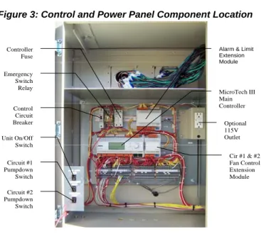
Figure 3: Control and Power Panel Component Location
Clearance Requirements
Notes:
1 Minimum side clearance between two units is 12 feet (3.7 meters).
2 Unit must not be installed in a pit or enclosure that is deeper or taller than the height of the unit unless extra clearance is provided per note 4.
3 Minimum clearance on each side is 8 feet (2.4 meters) when installed in a pit no deeper than the unit height.
4 Minimum side clearance to a side wall or building taller than the unit height is 6 feet (1.8 meters), provided no solid wall above 6 feet (1.8 meters) is closer than 12 feet (3.7 meters) to the opposite side of the unit.
5 Do not mount electrical conduits where they can block service access to compressor controls, refrigerant driers or valves.
6 There must be no obstruction of the fan discharge.
7 Field installed switches must not interfere with service access or airflow.
Figure 4: Clearance Requirements DANGER
Disconnect, lockout and tag all power to the unit before servicing condenser fan motors or compressors. Failure to do so can cause bodily injury or death.
Fan Contactors, 1 per Fan Circuit #1
Cir# 1, Fan Circuit Breaker
Fan Contactors 1 per Fan, Circuit #2 Phase/Voltage
Monitor
120/24V Transformer
Line/120V Transformer NOTES:
1. The Emergency Switch Relay de-energizes circuit #1 and #2 control power when activated, causing an immediate compressor and fan shutdown. The red emergency button switch is located on the bottom front of the control panel door.
2. The control power transformer is located in the power panel adjacent to the control panel.
3. Additional extension (aka extension) modules are located elsewhere on the chiller.
Alarm & Limit Extension Module
MicroTech III Main Controller
Optional 115V Outlet
Cir #1 & #2 Fan Control Extension Module Controller
Fuse Emergency Switch Relay
Control Circuit Breaker Unit On/Off Switch Circuit #1 Pumpdown Switch Circuit #2 Pumpdown Switch
g , , g
Single Point Disconnect Switch
Compressor #1 Circuit Breaker
Compressor #2 Circuit Breaker
5ft (1.5m) if open fence or 50% open wall if solid wall (see note3 for pit)
5ft (1.5m) if open fence or 50% open wall if solid wall (see note 3 for pit)
No obstructions.
Recommended area required for unit operation, air flow and maintenance access.
3ft (1m) for service
See Note 5 Wall or Fence Air Flow
No obstructions allowed above unit at any height See notes 2 & 4
concerning wall height at unit sides.
6ft (1.8m) 6ft (1.8m) 4ft (1.2m)
For electric panel access
Installation and Startup
Restricted Air Flow
General
The clearances required for design operation of Pathfinder air- cooled chillers are described in the previous section.
Occasionally, these clearances cannot be maintained due to site restrictions such as units being too close together or a fence or wall restricting airflow, or both. Pathfinder chillers have several features that may help mitigate the penalties attributable to restricted airflow.
"The condenser section is "W" shaped, as shown below. This allows inlet air for these coils to come in from both sides and the bottom. All the coils in one "V" section serve one compressor. Each compressor has its own independent refrigerant circuit.
"The MicroTech III control is proactive in response to "off- design conditions". In the case of single or compounded influences restricting airflow to the unit, the microprocessor will act to keep the unit running (at reduced capacity), rather than allowing a shut-off on high discharge pressure.
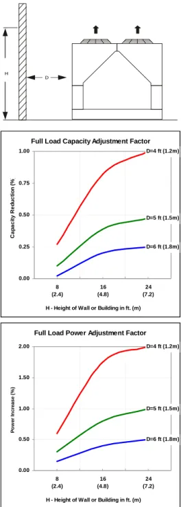
Case 1: Building or Wall on One Side of One Unit The existence of a screening wall or the wall of a building in close proximity to an air-cooled chiller is common in both rooftop and ground level applications. Hot air recirculation on the coils adjoining the wall will increase compressor discharge pressure, decreasing capacity and increasing power
consumption.
When close to a wall, it is desirable to place chillers on the north or east side of them. It is also desirable to have prevailing winds blowing parallel to the unit's long axis. The worst case is to have wind blowing hot discharge air into the wall.
Figure 5: Unit Adjacent to Wall - Adjustment Factors
Building
Full Load Capacity Adjustment Factor D=4 ft (1.2m)
D=5 ft (1.5m)
D=6 ft (1.8m)
0.00 0.25 0.50 0.75 1.00
8 (2.4)
16 (4.8)
24 (7.2) H - Height of Wall or Building in ft. (m)
Capacity Reduction (%)
Full Load Power Adjustment Factor D=4 ft (1.2m)
D=5 ft (1.5m)
D=6 ft (1.8m)
0.00 0.50 1.00 1.50 2.00
8 (2.4)
16 (4.8)
24 (7.2) H - Height of Wall or Building in ft. (m)
Power Increase (%)
H
D
Installation and Startup
Case 2: Two Units Side By Side
Two or more units sited side by side are common. If spaced closer than 12 feet (3.7 meters) it is necessary to adjust the performance of each unit; circuits adjoining each other are affected. If one of the two units also has a wall adjoining it, see Case 1. Add the two adjustment factors together and apply to the unit located between the wall and the other unit.
Mounting units end to end will not necessitate adjusting performance.
Do not use pit or solid wall surrounds where the ambient air temperature exceeds 105F (40C).
Figure 6: Two Units Side by Side - Adjustment Factors
Case 3: Three or More Units Side By Side
When three or more units are side by side, the outside chillers (1 and 3 in this case) are influenced by the middle unit only on their inside circuits. Their adjustment factors will be the same as Case 2. All inside units (only number 2 in this case) are influenced on both sides and must be adjusted by the factors shown below.
Figure 7: Three or More Units - Adjustment Factor
Full Load Capacity Adjustment Factor
0.00 0.50 1.00 1.50
6 (1.8)
8 (2.4)
10 (3.0)
12 (3.6) Distance Between Units in ft. (m)
Capacity Reduction (%)
Full Load Power Adjustment Factor
0.00 0.50 1.00 1.50 2.00 2.50 3.00
6 (1.8)
8 (2.4)
10 (3.0)
12 (3.6) Distance Between Units in ft. (m)
Power Increase (%)
Full Load Capacity Adjustment Factor
0.00 1.00 2.00 3.00
8 (2.4)
12 (3.6)
16 (4.8)
20 (6.1) Distance Between Units in ft. (m)
Capacity Reduction (%)
Full Load Power Adjustment Factor
0.00 2.00 4.00 6.00
8 (2.4)
12 (3.6)
16 (4.8)
20 (6.1) Distance Between Units in ft. (m)
Power Increase (%)
Installation and Startup
Case 4: Open Screening Walls
Decorative screening walls are often used to help conceal a unit either on grade or on a rooftop. Design these walls such that the combination of their open area and distance from the unit do not require performance adjustment. It is assumed that the wall height is equal to or less than the unit height when mounted on its base support. This is usually satisfactory for concealment. If the wall height is greater than the unit height, see Case 5, Pit Installation.
The distance from the sides of the unit to the side walls must be sufficient for service, such as opening control panel doors.
If each side wall is a different distance from the unit, the distances can be averaged providing either wall is not less than 8 feet (2.4 meters) from the unit. For example, do not average 4 feet and 20 feet to equal 12 feet (1 meter and 5 meters to equal 3 meters).
Figure 8: Open Screening Walls - Adjustment Factors
Case 5, Pit/Solid Wall Installation
Pit installations can cause operating problems. Use care if they are to be used on an installation. Recirculation and restriction can both occur. A solid wall surrounding a unit is substantially the same as a pit and the data presented here should be used.
Steel grating is sometimes used to cover a pit to prevent accidental falls or trips into the pit. The grating material and installation design must be strong enough to prevent such accidents, yet provide abundant open area or serious recirculation problems will occur. Have any pit installation reviewed by the McQuay sales representative prior to installation to make sure it has sufficient air-flow
characteristics. The installation design engineer must approve the work to avoid an unreasonable risk of accident.
Figure 9: Pit Installation - Adjustment Factors
Wall Fre e Are a vs D istance
0 .00 2 .00 4 .00 6 .00 8 .00
0 1 0 2 0 3 0 4 0 5 0
% Ope n Wall Ar e a
D - Distance from Wall to Unit in Ft. (m)
Fu ll Load P owe r Ad justme nt F ac tor
D =6 ft (1 .8 m )
D= 8 ft (2 .4 m )
D= 1 0 ft (3 .1 m )
0 .0 0 2 .0 0 4 .0 0 6 .0 0 8 .0 0
8 (2 .4 )
1 0 (3 .1 )
1 2 (3 .7 )
1 4 (4 .3 ) H - He ig ht of W a ll or Building in ft. ( m )
Power Increase (%)
Installation and Startup
Chilled Water
It is recommended that the chilled water pumps' starters be wired to, and controlled by, the chiller's microprocessor. The controller will energize the pump whenever at least one circuit on the chiller is enabled to run, whether there is a call for cooling or not. The control will also start the pump when freezing temperatures are approached. Wiring connection points are shown in Figure 23, page 30.
Water Piping
Due to the variety of piping practices, follow the
recommendations of local authorities. They can supply the installer with the proper building and safety codes required for a proper installation.
Design the piping with a minimum number of bends and changes in elevation to keep system cost down and performance up. It should contain:
1 Vibration eliminators to reduce vibration and noise transmission to the building.
2 Shutoff valves to isolate the unit from the piping system during unit servicing.
3 Manual or automatic air-vent valves at the high points of the system and drains at the low parts in the system. The evaporator should not be the highest point in the piping system.
4 Some means of maintaining adequate system water pressure (i.e., expansion tank or regulating valve).
5 Water temperature and pressure indicators located at the evaporator inlet and outlet to aid in unit servicing. Any connections should be made prior to filling the system with water.
6 A strainer to remove foreign matter from the water before it enters the pump. Place the strainer far enough upstream to prevent cavitation at the pump inlet (consult pump manufacturer for recommendations). The use of a strainer will prolong pump life and help maintain high system performance levels. Note: A 20-mesh strainer must also be placed in the supply water line just prior to the inlet of the evaporator. This will aid in preventing foreign material from entering the evaporator and causing damage or decreasing its performance. Care must also be exercised if welding pipe or flanges to the evaporator connections to prevent any weld slag from entering the vessel.
7 Any water piping to the unit must be protected to prevent freeze-up if below freezing temperatures are expected.
8 If the unit is used as a replacement chiller on a previously existing piping system, flush the system thoroughly prior to unit installation. Perform regular chilled water analysis and chemical water treatment immediately at equipment start-up.
9 In the event glycol is added to the water system as a late addition for freeze protection, recognize that the
refrigerant suction pressure will be lower, cooling performance less, and water side pressure drop greater. If the percentage of glycol is large, or if propylene is employed in lieu of ethylene glycol, the added pressure drop and loss of performance could be substantial.
10 For ice making or low temperature glycol operation, a different freezestat pressure value is usually required.
The freezestat setting can be manually changed through the MicroTech III controller.
Make a preliminary leak check prior to insulating the water piping and filling the system.
Include a vapor barrier with the piping insulation to prevent moisture condensation and possible damage to the building structure. It is important to have the vapor barrier on the outside of the insulation to prevent condensation within the insulation on the cold surface of the pipe.
System Water Volume
All chilled water systems need adequate time to recognize a load change, respond to that load change and stabilize, without undesirable short cycling of the compressors or loss of control.
In air conditioning systems, the potential for short cycling usually exists when the building load falls below the minimum chiller plant capacity or on close-coupled systems with very small water volumes.
Some of the things the designer should consider when looking at water volume are the minimum cooling load, the minimum chiller plant capacity during the low load period and the desired cycle time for the compressors.
Assuming that there are no sudden load changes and that the chiller plant has reasonable turndown, a rule of thumb of
"gallons of water volume equal to two to three times the chilled water gpm flow rate" is often used.
A properly designed storage tank should be added if the system components do not provide sufficient water volume.
Variable Speed Pumping
Variable water flow involves reducing the water flow through the evaporator as the load decreases. McQuay chillers are designed for this duty, provided that the rate of change in water flow is slow, and the minimum and maximum flow rates for the vessel are not exceeded.
The recommended maximum change in water flow is 10 percent of the change per minute. For example, if the
maximum (design) flow is 200 gpm and the flow is reduced to a minimum of 140 gpm, the change in flow is 60 gpm, so the maximum change per minute would be 10% of 60, or 6 gpm per minute. It would take ten minutes to change the flow through the entire range.
The water flow through the vessel must remain between the minimum and maximum values listed on page 19. If flow drops below the minimum allowable, large reductions in heat
Installation and Startup
transfer can occur. If the flow exceeds the maximum rate, excessive pressure drop and tube erosion can occur.
Evaporator Freeze Protection
Pathfinder chillers are equipped with thermostatically controlled evaporator heaters that help protect against freeze- up down to -20°F (-28°C). For additional protection, at least one of the followingprocedures should be used during periods of sub-freezing temperatures:
1 Adding of a concentration of a glycol anti-freeze with a freeze point 10°F. below the lowest expected
temperature. This will result in decreased capacity and increased pressure drop.
Note: Do not use automotive grade antifreezes as they contain inhibitors harmful to chilled water systems. Use only glycols specifically designated for use in building cooling systems.
2 Draining the water from outdoor equipment and piping and blowing the chiller tubes dry from the chiller. Do not energize the chiller heater when water is drained from the vessel.
3 Providing operation of the chilled water pump, circulating water through the chilled water system and through the evaporator
Note: The heaters come from the factory connected to the control power circuit. The control power can be rewired in the field to a separate 115V supply (do not wire directly to the heater). See the field wiring diagram on page 30. If this is done, it should power the entire control circuit.
Mark the disconnect switch clearly to avoid accidental deactivation of the heater during freezing temperatures.
Exposed chilled water piping also requires protection. If the evaporator is drained for winter freeze protection, the heaters must be de-energized to prevent heater burnout..
Flow Switch
A flow switch must be included in the chilled water system to prove that there is adequate water flow before the unit can start. It also serves to shut down the unit in the event that water flow is interrupted in order to guard against evaporator freeze- up.
A factory-mounted, solid state, thermal dispersion flow switch is available as an option. A field-installed version is also available as a kit (Accessory part number 332688401).
A paddle-type flow switch for field mounting and wiring is also available as a kit (Accessory part number 017503300). It is adaptable to pipe sizes from 1" (25mm) to 8" (203mm).
Certain minimum flow rates are required to close the switch and are listed in Table 3. Installation should be as shown in Figure 10.
Electrical connections in the unit control center should be made at terminals 60 and 67 from switch terminals Y and R.
The normally open contacts of the flow switch should be wired between these two terminals. Flow switch contact quality must be suitable for 24 VAC, low current (16ma). Flow switch wire must be in separate conduit from any high voltage conductors (115 VAC and higher) and have an insulation rating of 600 volts.
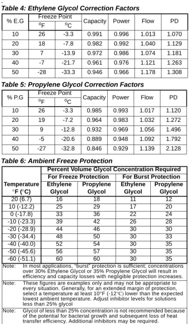
Table 2: Freeze Protection
Temp.
F (C)
% Volume Glycol Concentration Required For Freeze Protection For Burst Protection
Ethylene Glycol
Propylene Glycol
Ethylene Glycol
Propylene Glycol
20 (6.7) 16 18 11 12
10 (-12.2) 25 29 17 20
0 (-17.8) 33 36 22 24
-10 (-23.3) 39 42 26 28
-20 (-28.9) 44 46 30 30
-30 (-34.4) 48 50 30 33
-40 (-40.0) 52 54 30 35
-50 (-45.6) 56 57 30 35
-60 (-51.1) 60 60 30 35
Note: “Freeze protection” maintains the solution ina pumpable, usable liquid state. “Burst protection” prevents pipes from rupturing, but solution may be in a gel state and not pumpable. In most
applications, “burst” protection is sufficient; concentrations over 30%
Ethylene Glycol or 35% Propylene Glycol will result in efficiency and capacity losses with negligible protection increases
Note: These figures are examples only and cannot be appropriate to every situation. Generally, for an extended margin of protection, select a temperature at least 15°F lower than the expected lowest ambient temperature. Inhibitor levels should be adjusted for solutions less than 25% glycol.
Note: Glycol of less than 25% concentration is not recommended because of the potential for bacterial growth and loss of efficiency.
Flow direction marked on s wit ch
1" (25mm) NPT flow switch connection
Tee
1 1/ 4" (32mm) pipe dia. min. before switch 1 1/4" (32mm) pipe
dia. min. after switch
Flow direction marked on swit ch
1" (25mm) NPT f low switch connection
1 1/4" (32mm) pipe dia. min. before switch 1 1/4" (32mm) pipe
dia. min. after switch
Tee
Installation and Startup
Figure 10: Typical Field Water Piping
Note: Connections for vent and drain fittings are located on the top and bottom of the evaporator.
Note: Piping must be supported to avoid putting strain on the evaporator nozzles.
Refrigerant Charge
All packaged units are designed for use with R-134a and are shipped with a full operating charge. The operating charge for each unit is shown in the Physical Data Tables beginning on page 13.
Glycol Solutions
When using glycol anti-freeze solutions, the chiller's capacity, glycol solution flow rate, and pressure drop through the evaporator can be calculated using the following formulas and tables.
Note: The procedure below does not specify the type of glycol. Use the derate factors found in Table 4 or Table 5 forcorrections when using glycol.
1 Capacity - Cooling capacity is reduced from that with plain water. To find the reduced value, multiply the chiller’s water system tonnage by the capacity correction factor to find the chiller’s capacity when using glycol.
2 Flow - To determine flow (or Delta-T) knowing Delta-T (or flow) and capacity:
3 Pressure drop - To determine pressure drop through the evaporator when using glycol, enter the water pressure drop curve at the water flow rate. Multiply the water pressure drop found there by the "PD" factor to obtain corrected glycol pressure drop.
4 Power - To determine glycol system kW, multiply the water system kW by the factor designated "Power".
Test coolant with a clean, accurate glycol solution hydrometer (similar to that found in service stations) to determine the freezing point. Obtain percent glycol from the freezing point table below. On glycol applications, the supplier normally recommends that a minimum of 25% solution by weight be used for protection against corrosion or that additional inhibitors should be employed.
Note: Do not use automotive grade antifreeze. Industrial grade glycols must be used. Automotive antifreeze contains inhibitors that will cause plating on the copper tubes within the chiller evaporator.
The type and handling of glycol used must be consistent with local codes.
Performance Adjustment Factors
Ethylene and Propylene Glycol Factors
Pathfinder chiller units are designed to operate with leaving chilled fluid temperatures of 20.0°F to 60.0°F (-6.7°C to 15.6°C). Consult the local McQuay sales office for
performance outside these temperatures. Leaving chilled fluid temperatures below 40°F (4.4°C) result in evaporating temperatures at or below the freezing point of water and a glycol solution is required. MicroTech III control inhibits compressor unloading at leaving fluid temperatures below 30°F (-1°C)
Table 3: Paddle Type Flow Switch Flow Rates
Pipe Size inch 1 1/4 1 1/2 2 2 1/2 3 4 5 6 8
mm 32 38 51 63 76 102 127 153 204
(NOTE) - (2) (2) (3) (4) (4) (4) (5)
Min.
Adjst.
Flow gpm 5.8 7.5 13.7 18.0 27.5 65.0 125.0 190.0 205.0
Lpm 1.3 1.7 3.1 4.1 6.2 14.8 28.4 43.2 46.6
No Flow gpm 3.7 5.0 9.5 12.5 19.0 50.0 101.0 158.0 170.0
Lpm 0.8 1.1 2.2 2.8 4.3 11.4 22.9 35.9 38.6
Max.
Adjst.
Flow gpm 13.3 19.2 29.0 34.5 53.0 128.0 245.0 375.0 415.0
Lpm 3.0 4.4 6.6 7.8 12.0 29.1 55.6 85.2 94.3
No Flow gpm 12.5 18.0 27.0 32.0 50.0 122.0 235.0 360.0 400.0
Lpm 2.8 4.1 6.1 7.3 11.4 27.7 53.4 81.8 90.8
Note: 1A segmented 3-inch paddle (1, 2, and 3 inches) is furnished mounted, plus a 6-inch paddle loose.
Note: 2Flow rates for a 2-inch paddle trimmed to fit the pipe.
Note: 3Flow rates for a 3-inch paddle trimmed to fit the pipe.
Note: 4Flow rates for a 3-inch paddle.
Note: 5Flow rates for a 6-inch paddle.
Vent
Drain
Gate Valve Water Strainer Vibration Eliminator Valved Pressure
Gauge In
Out Protect All Field Piping
Against Freezing Flow
Vibration Eliminator
Flow Switch Balancing
Valve Gate Valve
Flow Liquid
Suction
T Delta
factor flow GPM tons
24
Installation and Startup
.
Electrical Connections
All wiring must be done in accordance with applicable local and national codes. Pathfinder units can be ordered with either standard multi-point power or optional single point power connections and with various disconnect and circuit breaker options. Wiring within the unit is sized in accordance with the U.S.A. National Electrical Code. Field-supplied disconnect switches are required if not factory-supplied with the unit.
Note: Disconnect switches are molded case construction with lockable through-the-door handles. They can be used to remove the unit/
circuit from the power system.
Note: The individual compressor isolation circuit breakers for each circuit isolate the compressor and do not have through-the-door handles.
They are operable only after the panel doors are opened.
Note: The high short circuit rated panel means that a short circuit current up to the ratings shown in Table 8, Interrupt Ratings (kAmps)will be contained in the panel. There is a short period of time when the circuit breaker will short circuit before opening a circuit that can damage downstream components. In other words, the enclosure is stronger than a standard enclosure. It has a high interrupt rated disconnect switch.
Note: The factory-mounted control power transformer is protected by fuses.
Note: Condenser fans are protected and isolated by circuit breakers.
Disconnecting means are addressed by Article 440 of the U.S.A. National Electrical Code (NEC), which requires
“disconnecting means capable of disconnecting air conditioning and refrigerating equipment including motor- compressors, and controllers from the circuit feeder.” Select and locate the disconnect switch per the NEC guidelines.
Maximum recommended fuse sizes are given in the electrical data tables of this catalog for help in sizing the disconnect.
Terminals are provided in a unit control panel for optional field hookup of the control circuit to a separate fused 115-volt power supply in lieu of the standard factory installed control transformer.
Table 4: Ethylene Glycol Correction Factors
% E.G Freeze Point
Capacity Power Flow PD
oF oC
10 26 -3.3 0.991 0.996 1.013 1.070
20 18 -7.8 0.982 0.992 1.040 1.129
30 7 -13.9 0.972 0.986 1.074 1.181
40 -7 -21.7 0.961 0.976 1.121 1.263
50 -28 -33.3 0.946 0.966 1.178 1.308
Table 5: Propylene Glycol Correction Factors
% P.G Freeze Point
Capacity Power Flow PD
oF oC
10 26 -3.3 0.985 0.993 1.017 1.120
20 19 -7.2 0.964 0.983 1.032 1.272
30 9 -12.8 0.932 0.969 1.056 1.496
40 -5 -20.6 0.889 0.948 1.092 1.792
50 -27 -32.8 0.846 0.929 1.139 2.128
Table 6: Ambient Freeze Protection
Temperature
F (C)
Percent Volume Glycol Concentration Required For Freeze Protection For Burst Protection Ethylene
Glycol
Propylene Glycol
Ethylene Glycol
Propylene Glycol
20 (6.7) 16 18 11 12
10 (-12.2) 25 29 17 20
0 (-17.8) 33 36 22 24
-10 (-23.3) 39 42 26 28
-20 (-28.9) 44 46 30 30
-30 (-34.4) 48 50 30 33
-40 (-40.0) 52 54 30 35
-50 (-45.6) 56 57 30 35
-60 (-51.1) 60 60 30 35
Note: In most applications, “burst” protection is sufficient; concentrations over 30% Ethylene Glycol or 35% Propylene Glycol will result in efficiency and capacity losses with negligible protection increases.
Note: These figures are examples only and may not be appropriate to every situation. Generally, for an extended margin of protection, select a temperature at least 10°F (-12°C) lower than the expected lowest ambient temperature. Adjust inhibitor levels for solutions less than 25% glycol
Note: Glycol of less than 25% concentration is not recommended because of the potential for bacterial growth and subsequent loss of heat transfer efficiency. Additional inhibitors may be required.
Table 7: Electric Power Connection Option Multi-Point
Power Connection
Single-Point Power Connection Standard:
Disconnect switch per circuit, no compressor isolation circuit breakers
Optional:
one power block, compressor isolation circuit breakers Optional:
High interrupt rated disconnect switches, no compressor isolation
circuit breakers
Optional:
One disconnect switch replacing the power block, compressor
isolation circuit breakers Optional:
High short circuit current rated panel, high interrupt disconnect switches, no compressor isolation
circuit breakers
Optional:
One high interrupt rated disconnect switch, compressor
isolation circuit breakers Optional:
High short circuit current rated panel, one high interrupt disconnect switch, compressor
isolation circuit breakers
Table 8: Interrupt Ratings (kAmps)
VOLTAGE
STANDARD SHORT CIRCUIT
PANEL RATING
HIGH INTERRUPT DISCONNECT
SWITCH
HIGH SHORT CIRCUIT
RATED PANEL
460 35 kA 35 kA 65 kA
Physical Data
Physical Data
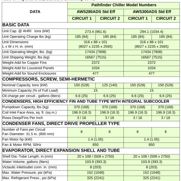
Table 9: Physical Data, Standard Efficiency 50 Hz
DATA
Pathfinder Chiller Model Numbers AWS280ADS Std Eff AWS300ADS Std Eff CIRCUIT 1 CIRCUIT 2 CIRCUIT 1 CIRCUIT 2 BASIC DATA
Unit Cap. @ AHRI tons (kW) 273.4 (961.6) 294.1 (1034.4)
Unit Operating Charge lbs (kg) 185 (84) 185 (84) 185 (84) 185 (84) Unit Dimensions
L x W x H, in. (mm)
316 x 88 x 101 (8027 x 2235 x 2565)
316 x 88 x 101 (8027 x 2235 x 2565)
Unit Operating Weight, lbs. (kg) 17434 (7908) 17434 (7908)
Unit Shipping Weight, lbs (kg) 16567 (7515) 16567 (7515)
Weight-Add for Copper Fins 2372 2372
Weight-Add for Louvered Panels 1034 1034
Weight-Add for Sound Enclosures 477 477
COMPRESSORS, SCREW, SEMI-HERMETIC
Nominal Capacity, tons (kW) 150 (528) 125 (140) 150 (528) 150 (528)
Minimum Capacity (% of Full Load) 15 15
Oil charge per circuit , gallons (liters) 6.6 (25) 6.6 (25) 6.6 (25) 6.6 (25) CONDENSERS, HIGH EFFICIENCY FIN AND TUBE TYPE WITH INTEGRAL SUBCOOLER Pumpdown Capacity, lbs (kg) 370 (168) 370 (168) 370 (168) 370 (168) Coil Inlet Face Area, sq. ft. (sq m.) 196.9 (18.3) 196.9 (18.3) 196.9 (18.3) 196.9 (18.3)
Rows Deep/Fins Per Inch 3 / 16 3 / 16 3 / 16 3 / 16
CONDENSER FANS, DIRECT DRIVE PROPELLER TYPE
Number of Fans per Circuit
Fan Diameter: 31.5 in. (800 mm) 8 8 8 8
Fan Motor hp (kW) 1.4 (1.05) 1.4 (1.05)
Fan & Motor RPM, 50Hz 850 850
EVAPORATOR, DIRECT EXPANSION SHELL AND TUBE
Shell Dia.-Tube Length, in.(mm) 20 x 108 / (508 x 2750) 20 x 108 / (508 x 2750)
Water Volume, gallons (liters) 103.9 (393.3) 103.9 (393.3)
Victaulic inlet/outlet conn. in. (mm) 8 (203) 8 (203)
Max. Water Pressure, psi (kPa) 152 (1048) 152 (1048)
Max. Refrigerant Press., psi (kPa) 325 (2241) 325 (2241)
Physical Data
Table 10: Physical Data, High Efficiency 50 Hz
DATA
Pathfinder Chiller Model Numbers
AWS300ADH High Eff AWS320ADH High Eff AWS350ADH High Eff CIRCUIT 1 CIRCUIT 2 CIRCUIT 1 CIRCUIT 2 CIRCUIT 1 CIRCUIT 2 BASIC DATA
Unit Cap. @ AHRI tons (kW) 287.4 (1010.8) 314.8 (1107.2) 341.6 (1201.4)
Unit Operating Charge lbs (kg) 200 (91) 200 (91) 237 (107) 237 (107) 237 (107) 237 (107) Unit Dimensions
L x W x H, in. (mm)
316 x 88 x 101 (8027 x 2235 x 2565)
387 x 88 x 101 (9830 x 2235 x 2565)
387 x 88 x 101 (9830 x 2235 x 2565)
Unit Operating Weight, lbs. (kg) 17724 (8040) 19656 (8916) 19656 (8916)
Unit Shipping Weight, lbs (kg) 16857 (7646) 18789 (8523) 18789 (8523)
Weight-Add for Copper Fins 2372 2968 2968
Weight-Add for Louvered Panels 1034 1262 1262
Weight-Add for Sound Enclosures 477 477 477
COMPRESSORS, SCREW, SEMI-HERMETIC
Nominal Capacity, tons (kW) 150 (528) 150 (528) 175 (615) 150 (528) 175 (615) 175 (615)
Minimum Capacity (% of Full Load) 15 15 15
Oil charge per circuit , gallons (liters) 6.6 (25) 6.6 (25) 6.6 (25) 6.6 (25) 6.6 (25) 6.6 (25)
CONDENSERS, HIGH EFFICIENCY FIN AND TUBE TYPE WITH INTEGRAL SUBCOOLER
Pumpdown Capacity, lbs (kg) 370 (168) 370 (168) 462 (210) 462 (210) 462 (210) 462 (210) Coil Inlet Face Area, sq. ft. (sq m.) 196.9 (18.3) 196.9 (18.3) 246.1 (22.8) 246.1 (22.8) 246.1 (22.8) 246.1 (22.8)
Rows Deep/Fins Per Inch 3 / 16 3 / 16 3 / 16 3 / 16 3 / 16 3 / 16
CONDENSER FANS, DIRECT DRIVE PROPELLER TYPE
Number of Fans per Circuit
Fan Diameter: 31.5 in. (800 mm) 8 8 10 10 10 10
Fan Motor hp (kW) 1.4 (1.05) 1.4 (1.05) 1.4 (1.05)
Fan & Motor RPM, 50Hz 850 850 850
EVAPORATOR, DIRECT EXPANSION SHELL AND TUBE
Shell Dia.-Tube Length, in.(mm) 20 x 108 / (508 x 2750) 20 x 108 / (508 x 2750) 20 x 108 / (508 x 2750)
Water Volume, gallons (liters) 103.9 (393.3) 103.9 (393.3) 103.9 (393.3)
Victaulic inlet/outlet conn. in. (mm) 8 (203) 8 (203) 8 (203)
Max. Water Pressure, psi (kPa) 152 (1048) 152 (1048) 152 (1048)
Max. Refrigerant Press., psi (kPa) 325 (2241) 325 (2241) 325 (2241)
Dimensions
Dimensions
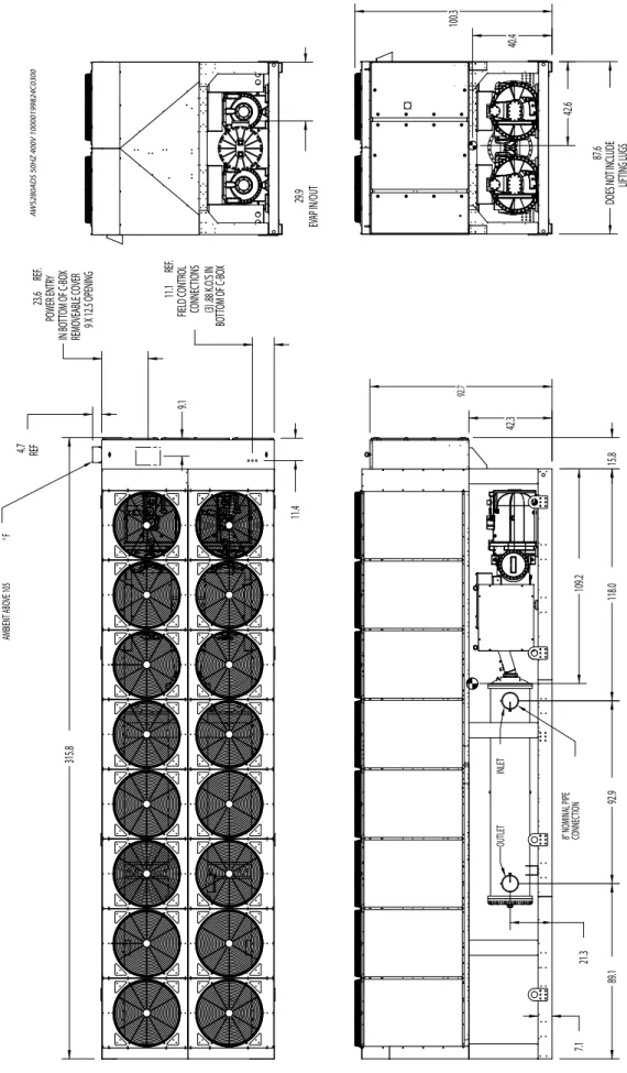
Figure 11: Physical Dimensions - AWS280 Standard Efficiency, 50 Hz Note: All dimensions in decimal inches. Allow 1-inch manufacturing tolerance on all dimensions
109.2
42.3 21.3 92.9118.089.115.8
7.1
92.7
8" NOMINAL PIPE CONNEC
TION
INLETOUTLET
11.4
11.1 REF. FIELD CONTROL CONNECTIONS (3) .88 K.O.'S IN BOTTOM OF C-BOX
9.1
23.6 REF. POWER ENTRY IN BOTTOM OF C-BOX REMOVEABLE COVER 9 X 12.5 OPENING
4.7 REF
315.8
VENT - FOR UNITS WITH AMBIENT ABOVE 105°F 40.4 42.6 87.6 DOES NOT INCLUDE LIFTING LUGS
100.3
29.9 EVAP IN/OUT
AWS280ADS 50HZ 400V 10000199824C0300
Dimensions
Figure 12: Physical Dimensions - AWS300 Standard Efficiency, 50 Hz Note: All dimensions in decimal inches. Allow 1-inch manufacturing tolerance on all dimensions
109.2
42.3 21.3 92.9118.089.115.8
7.1
92.7
8" NOMINAL PIPE CONNEC
TION
INLETOUTLET
11.4
11.1 REF. FIELD CONTROL CONNECTIONS (3) .88 K.O.'S IN BOTTOM OF C-BOX
9.1
23.6 REF. POWER ENTRY IN BOTTOM OF C-BOX REMOVEABLE COVER 9 X 12.5 OPENING
4.7 REF
315.8
VENT - FOR UNITS WITH AMBIENT ABOVE 105°F 40.4 42.6 87.6 DOES NOT INCLUDE LIFTING LUGS
100.3
29.9 EVAP IN/OUT
AWS300ADS 50HZ 400V 10000199824C0300
Dimensions
Figure 13: Physical Dimensions - AWS300 High Efficiency, 50 Hz
Note: All dimensions in decimal inches. Allow 1-inch manufacturing tolerance on all dimensions
108.5
42.3 21.3 92.9118.089.115.8
74.0 7.1
8" NOMINAL PIPE CONNEC
TION
INLETOUTLET
11.4
11.1 REF. FIELD CONTROL CONNECTIONS (3) .88 K.O.'S IN BOTTOM OF C-BOX
9.1
23.6 REF. POWER ENTRY IN BOTTOM OF C-BOX REMOVEABLE COVER 9 X 12.5 OPENING
4.7 REF
315.8
VENT - FOR UNITS WITH AMBIENT ABOVE 105°F 39.7 42.7 87.6 DOES NOT INCLUDE LIFTING LUGS
100.3
29.9 EVAP IN/OUT
AWS300ADH 50HZ 400V 10000199824C0100
Dimensions
Figure 14: Physical Dimensions - AWS320 High Efficiency, 50 Hz
Note: All dimensions in decimal inches. Allow 1-inch manufacturing tolerance on all dimensions
128.221.3 92.9118.0160.0
7.1
92.7 42.3 15.8
8" NOMINAL PIPE CONNEC
TION
INLETOUTLET
11.4
11.1 REF. FIELD CONTROL CONNECTIONS (3) .88 K.O.'S IN BOTTOM OF C-BOX 9.1
23.6 REF. POWER ENTRY IN BOTTOM OF C-BOX REMOVEABLE COVER 9 X 12.5 OPENING
4.7 REF
386.7
VENT - FOR UNITS WITH AMBIENT ABOVE 105°F 42.3 43.2 87.6 DOES NOT INCLUDE LIFTING LUGS
100.3
29.9 EVAP IN/OUT
AWS320ADH 400V 50HZ 10000199826C010B 128.221.3 92.9118.0160.0
7.1
92.7 42.3 15.8
8" NOMINAL PIPE CONNEC
TION
INLETOUTLET
11.4
11.1 REF. FIELD CONTROL CONNECTIONS (3) .88 K.O.'S IN BOTTOM OF C-BOX 9.1
23.6 REF. POWER ENTRY IN BOTTOM OF C-BOX REMOVEABLE COVER 9 X 12.5 OPENING
4.7 REF
386.7
VENT - FOR UNITS WITH AMBIENT ABOVE 105°F 42.3 43.2 87.6 DOES NOT INCLUDE LIFTING LUGS
100.3
29.9 EVAP IN/OUT
AWS320ADH 400V 50HZ 10000199826C010B
Dimensions
Figure 15: Physical Dimensions - AWS350 High Efficiency, 50 Hz
Note: All dimensions in decimal inches. Allow 1-inch manufacturing tolerance on all dimensions
128.221.3 92.9118.0160.0
7.1
92.7 42.3 15.8
8" NOMINAL PIPE CONNEC
TION
INLETOUTLET
11.4
11.1 REF. FIELD CONTROL CONNECTIONS (3) .88 K.O.'S IN BOTTOM OF C-BOX 9.1
23.6 REF. POWER ENTRY IN BOTTOM OF C-BOX REMOVEABLE COVER 9 X 12.5 OPENING
4.7 REF
386.7
VENT - FOR UNITS WITH AMBIENT ABOVE 105°F 42.3 43.2 87.6 DOES NOT INCLUDE LIFTING LUGS
100.3
29.9 EVAP IN/OUT
AWS350ADH 400V 50HZ 10000199826C010B